Abstract
In this article we propose a physical approach to the linear sampling method (LSM) for a possibly inhomogeneous and lossy background, whereby the modified far-field equation at the basis of the method can be regarded as a constraint on the power fluxes carried by the Poynting vector associated with the scattered field. Under appropriate assumptions on the flow lines of this Poynting vector, the general theorem inspiring the LSM (and concerning the existence of approximate solutions to the modified far-field equation) can be reformulated in a different way, which is more appropriate to explain the performance of the method.
1. Introduction
The linear sampling method (LSM) Citation1–4 is a well-known algorithm for visualizing the support of an unknown object by processing the data of a time-harmonic scattering experiment, and it can be considered the first of a set of qualitative methods Citation5 in the field of inverse scattering. The strong points of these methods (intrinsic linearity, short computational times, no need for a priori information on the scatterer, etc.) make them an effective approach for a large variety of inverse scattering problems.
However, qualitative methods are based on equations that are artificially formulated, i.e. do not derive from physical laws. This lack of a physical foundation seems to be responsible for at least one of the open problems Citation5,Citation6 concerning, in particular, the LSM. Indeed, the far-field equation at the basis of the LSM is known to admit approximate solutions whose L2-norms behave as good indicator functions for the support of the scatterer (i.e., functions bounded inside and arbitrarily large outside the unknown object), but there is a priori no reason why computing the L2-norm of a (Tikhonov) regularized solution of the far-field equation, as requested by the implementation of the LSM, should provide one of these indicator functions.
In order to overcome this difficulty, the far-field equation at the basis of the LSM can be modified so to obtain a different qualitative method, i.e. the factorization method (FM), first formulated in Citation7 and extensively described in Citation8. The theoretical foundation of the FM is much more sound than that of the LSM; moreover, the FM can provide a deep insight into the LSM, as shown in Citation9–11. In particular, in Citation10 the LSM is reformulated and mathematically justified by means of results holding for the FM. However, this approach is restrictive from the viewpoint of scattering conditions, since the FM is, so far, significantly less general than the LSM Citation5,Citation6.
This gap motivated the physics-based approach to the LSM proposed in a recent article Citation12, whereby the far-field equation of the LSM is regarded as a constraint on the power fluxes carried by the Poynting vector associated with the scattered electromagnetic field. It is shown there that, under some assumptions on the flow lines of this Poynting vector in the background, any approximate (and, in particular, the Tikhonov regularized) solution of the far-field equation behaves as a good indicator function for the support of the unknown target. This approach is explained in detail in the case of a homogeneous and lossless background, and for an experimental set-up consisting of emitting and receiving antennas placed in the far-field region. However, the LSM can also be formulated when a lossy and inhomogeneous background is taken into account, and all the antennas are placed in the near-field region Citation13–15. Hence, in this article we want to show how the investigation pursued in Citation12 can be adapted to this more complex scenario. The main advantage of this approach is that the material properties of the scatterer (and, to a large extent, of the background) are irrelevant: we focus on the two-dimensional, penetrable case only to fix ideas and notations, but the key role in our framework is just played by the behaviour of the flow lines of the Poynting vector in the background medium (and not inside the scatterer). However, so far, this is also a limitation of our approach, since such behaviour is a posteriori observed by means of numerical simulations, and not theoretically predicted. Progress in this direction would probably require sophisticated tools of topological dynamics (see, e.g. Citation16), and is beyond the scope of the present investigation.
This article is organized as follows. In Section 2 we formulate the direct and the inverse scattering problems we are interested in, we summarize the LSM and highlight the theoretical open issue we want to address. Section 3 is concerned with the propagation of electromagnetic power flux throughout the background: in particular, the role of the flow lines of the Poynting vector field associated with the scattered field is emphasized. Section 4 shows how the analysis of power fluxes can give an insight into the LSM when emitters and receivers are placed in the near-field and the far-field region, respectively: to this end, the investigation of Citation12 is adapted to the case of a lossy and inhomogeneous background. In Section 5 we perform some numerical simulations in order to catch the typical behaviour of the flow lines of the Poynting vector field, and we explain how this behaviour is related to the performance of the LSM. Section 6 addresses the situation where both emitters and receivers are in the near-field region, by pointing out its link with the case of far-field receivers, considered in the previous sections. Finally, our conclusions and hints for future work are presented in Section 7.
2. The direct and inverse scattering problems
We consider a time-harmonic electromagnetic wave of angular frequency ω > 0. First, we describe its propagation inside the background medium. The latter is assumed to be a penetrable, isotropic, infinitely long cylinder, whose physical and geometrical properties are the same on each plane perpendicular to its axis â. Let us choose any of these planes and identify it with ℝ2. Following the conventions of Section 9.1 in Citation17, we assign the refraction index of the background as
(1)
where
. We assume that there exists R0 > 0 such that ϵ(x) = ϵ0 > 0 and σ(x) = 0
, with
. In Ω0 the wavenumber is
, while the refraction index is n0 = 1. Then, if we define m(x) ≔ 1 − n(x), the support of m (denoted by supp m) is compact: we also require that supp m is piecewise homogeneous, i.e. there exists a finite number J of open C2-domains Ωj ⊂ ℝ2 where n(x) = nj ∈ ℂ ∀x ∈ Ωj, for j = 1, … , J, such that Ωi ∩ Ωj = ∅ for i ≠ j and
. Accordingly, the wavenumber is given by
(with Im[k(x)] ≥ 0) ∀x ∈ Ωj and ∀j = 0, … , J. The magnetic permeability is assumed to be constant everywhere, i.e. μ(x) = μ0 > 0 ∀x ∈ ℝ2.
The incident electric field is generated by a line source parallel to â, whose intersection x0 with the plane of interest is placed in Ω0. Accordingly, we can choose a coordinate system such that the incident field is expressed as
(2)
where
is the Hankel function of the first kind and of order zero (the dependence of the fields on the source point x0 will often be omitted in the following). This means that we are considering TM-polarized waves: then, the scattered and total electric field can be expressed as Es(x) = (0, 0, us(x)) and E(x) = (0, 0, u(x)), respectively. Starting from the time-harmonic and rescaled Maxwell equations (see Section 9.1 in Citation17)
(3)
and imposing the continuity of the tangential components of the total fields E and H across the surfaces where n(x) is discontinuous, easy computations show that the scattering problem can be formulated as follows: given the incident field ui as in (2), find the total field u ∈ C1(ℝ2 ∖ {x0}) such that Citation13
(4)
where the last relation expresses the Sommerfeld radiation condition. More precisely, Equation (4a) is written for each open domain Ωj and complemented by the transmission conditions imposing the continuity of both u and its normal derivative
across the discontinuity surfaces of n(x). Moreover, for each j = 1, … , J,
∀x ∈ Ωj: it follows from (4a) that u satisfies the Helmholtz equation in each homogeneous portion Ωj of the background, whence u is real-analytic in Ωj itself Citation5 (of course, it is also real-analytic in Ω0 ∖ {x0}). Since an analogous argument shows that ui, given by (2), is real-analytic in ℝ2 ∖ {x0}, the regularity properties of u also hold for the scattered field us = u − ui, except that us is real-analytic in x0 too.
The direct scattering problem (4) is equivalent Citation13,Citation17 to the Lippmann–Schwinger equation
(5)
where Bm ≔ supp m. In particular, the integral formulation (5) of problem (4) allows proving the well-posedness of the latter: if B is any open ball, centred at the origin, such that
and
, the solution u of (4) in
depends continuously on ui with respect to the maximum norm in
.
Now assume that a smooth, penetrable and cylindrical scatterer (with the same axis â and the same magnetic permeability μ0 as the background) is located in : more precisely, we assume that it takes up the closure
of an open, bounded and C2-domain
, such that
is connected and the lines of discontinuity of the refraction index are C2-curves. Accordingly, definition (1) is replaced by
(6)
with
, while the corresponding wavenumber is now given by
. The previous discussion is easily extended to this new framework: it suffices to replace everywhere n(x) with
(x). We consider the same incident field (2) as before, and we denote the new total and scattered fields as ũ and ũ s respectively. In particular, it is easy to realize Citation13,Citation14 that
(7)
is the field scattered by
when u, which is the Green's function for the background medium described by (1), is regarded as the incident field.
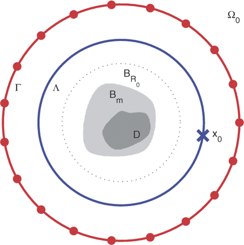
The qualitative inverse scattering problem considered here is to visualize the support of the scatterer by processing the data of an appropriate scattering experiment, starting from the knowledge of the background, i.e. of the refraction index n(x). We assume that the source point x0 can be moved along a circle Λ ≔ {x ∈ ℝ2 : |x| = RΛ}, while the receivers are located on a circle Γ ≔ {x ∈ ℝ2 : |x| = RΓ}, with RΛ, RΓ > R0. A schematic (and not in scale) representation of the physical set-up is shown in .
The LSM (as outlined, in particular, in Citation13,Citation14) is a procedure for solving this inverse problem. It is based on the modified far-field operator
(8)
and the corresponding modified far-field equation
(9)
written for each z in the investigation domain T, contained in the disk of boundary Γ. We point out that, in spite of the name of Equation (9), emitters and receivers are usually placed in the near-field region, as is reasonable when an inhomogeneous background is taken into account. In general, Equation (9) is unsolvable for almost all z ∈ T Citation14. However, the following theorem Citation13,Citation14 ensures that (9) admits ε-approximate solutions
whose L2(Λ)-norm can be used as an indicator function for
, since it is bounded inside D, blows up on ∂D and can be made arbitrarily large outside D.
Theorem 2.1
Let D, F, k0 be as above and assume that k0 is not a transmission eigenvalue. Then:
| i. | if z ∈ D, for every ε > 0 there exists a solution | ||||
| ii. | if | ||||
Inspired by this theorem, the LSM visualizes the scatterer by computing the Tikhonov regularized solution of Equation (9) and by plotting its L2(Λ)-norm for each sampling point z ∈ T. However, the main problem with this approach is that there is no guarantee that
behaves as the ε-approximate solution exhibited by the theorem (see Citation5,Citation6,Citation8–10,Citation15 for a detailed discussion of this point). Rather, remembering also that regularization prevents ε from vanishing (at least in presence of noise), an ‘ideal’ version of Theorem 2.1 would be the following: (i) if z ∈ D and ε > 0 is small enough, then any
satisfying (10) is such that limit (11) holds; (ii) if
and ε > 0 is small enough, there exists no
satisfying (10).
Nevertheless, without any further hypothesis, this ‘ideal’ version is clearly false: e.g. the new point (ii) is made impossible by point (ii) of Theorem 2.1. Then, the key-problem now is: what further hypotheses can we reasonably add in order to obtain the desired statement? To face this problem, in the following sections we shall analyse how time-averaged electromagnetic power is transported in the background medium, from both the analytical and numerical viewpoints.
3. The Poynting vector and the transport of power fluxes
As suggested by (8) and (9), the field ud plays a crucial role in the implementation of the LSM: then, in our framework, it is important to analyse ud from the viewpoint of energy transport. From Ed(x) = (0, 0, ud(x)) and the first equation of (3), we find the corresponding magnetic field . Then, remembering that
, we can compute the time-averaged Poynting vector associated with the scattered electromagnetic field (Ed, Hd) as Citation18,Citation19:
(13)
The previous regularity discussion implies that each component of 𝒮d is in C0(ℝ2) and real-analytic in
for each j = 0, … , J. We shall come back to this point later.
It is well known Citation18,Citation19 that the integral of the time-averaged Poynting vector field over a closed surface Σ with outward unit normal represents the real power outgoing from Σ. Of course, in our two-dimensional setting, we consider plane curves instead of surfaces: then, if γ is a non-autointersecting and piecewise smooth curve in ℝ2 (as always assumed in the following), we define the power flux of the field ud across γ as the power flux of the corresponding Poynting vector (13), i.e.
(14)
where ν(x) is the unit normal to γ at the point x and dl(x) denotes the standard linear measure on γ. In particular, if γ is the boundary (with outward unit normal) of a bounded, connected and regular domain Eγ ⊂ ℝ2 ∖ D, we can prove that the flux (14) is not greater than zero, since the background is, in general, lossy. To this end, it suffices to apply Gauss's divergence theorem in Eγ: remembering (13), (14) and observing that ud satisfies Equation (4a) in
, we get
(15)
where we used
, with
and Im[n(x)] ≥ 0 by (1). Of course, if the domain Eγ is a subset of the lossless region Ω0, the equality holds true at the end of (15).
It is now interesting to discuss the particular case where Eγ is a finite flow strip of ud in the background medium. To this end, we first recall that, given a point x1 ∈ ℝ2 ∖ D, the flow line of the plane vector field 𝒮d starting from x1 is defined as the solution x(τ) (for τ ≥ 0) of the Cauchy problem
(16)
For simplicity, we shall often refer to such x(τ) as the flow line
of ud starting from x1, although it is actually a flow line of 𝒮d. We observe that if x1 is taken inside one of the domains Ωj, the real-analyticity of 𝒮d in Ωj (remarked above) ensures the local existence and uniqueness of
; instead, if x1 is chosen just on the boundaries ∂D or ∂Ωj, the continuity of 𝒮d (in particular, the fact that it is not Lipschitz in a neighbourhood of x1) does not suffice to ensure the uniqueness of
. In other terms, when x1 belongs to a discontinuity curve of
(x), it may be a ramification point of ud, i.e. a point whence more than one flow line of ud can start. We shall denote with
the subset of ℝ2 ∖ D where ramification points may occur.
Then, let us consider finite flow strips of ud: they are open, connected and (almost everywhere) regular domains Eγ ⊂ ℝ2 ∖ D obtained via the following construction. Take two distinct points x1, x2 ∈ ℝ2 ∖ D and assume that they are neither ramification points, nor do they belong to the same flow line. Consider the two corresponding flow lines ,
and fix two other points, x3 in the image of
and x4 in the image of
. Hence, the arcs
and
are finite portions of flow lines and form the lateral boundary of a flow strip. Next, we close the latter by tracing two transverse sections, i.e. we consider two non-intersecting curves γ1 and γ2 connecting x1 with x2 and x3 with x4, respectively. The closed curve γ formed by γ1, γ2 and the arcs
,
is the boundary of the open domain Eγ, which shall be called a finite flow strip of ud. Now, by virtue of (15), we have that ℱγ(ud) ≤ 0; on the other hand, the power flux across the two arcs of flow lines is clearly zero. This amounts to saying that
, with outward unit normals ν1 to γ1 and ν2 to γ2; but we can change the orientation of one of them (say ν1, which then becomes inward), so that we find
. The last inequality expresses the property that the power outgoing from the finite flow strip through γ2 is not greater than the power ingoing through γ1, as expected in a possibly lossy background.
In general, the flow tubes of the Poynting vector field are responsible for the power transport throughout the propagation medium: in other terms, they transmit the energy of the electromagnetic field from one point to another in space. In our physical interpretation of the LSM, we are interested in tracking this transport phenomenon in the case of the Poynting vector 𝒮d given by (13). To this end, we need to assume that the flow strips of ud starting from ∂D reach the observation circle Γ with a regular behaviour. This means that a flow strip Eγ, with lateral boundary formed by two flow lines and
, should not intersect the scatterer D (in particular,
and
should not refold on D); furthermore, both
and
must intersect Γ in exactly one point. We shall fix these properties by means of appropriate definitions in the following.
We are now ready to use the concepts introduced above for investigating the modified far-field equation (9) from a power-flux perspective. Then, we conclude this section by pointing out that, although focused on the field ud, the previous discussion can be easily extended to any scattered field.
4. Power fluxes and the modified far-field equation: far-field measurements
As a first step, let us assume, for the moment, that the observation circle Γ is placed in the far-field region, i.e. RΓ → ∞: this assumption simplifies our framework and allows us to rely on the results of Citation12. We shall discuss the case of near-field measurements in Section 6; in any case, the emitters are placed on the near-field circle Λ.
We begin by stating the concept of (far-field) regularity for the flow lines and flow strips of the field ud.
Definition 4.1
Given a point x1 ∈ ℝ2 ∖ D, a flow line of ud starting from x1 is called regular if the following properties hold:
| 1. |
| ||||
| 2. |
| ||||
| 3. | if | ||||
Point (3) states that the flow line must approach a definite direction in the far-field region. This is in agreement with the Silver–Müller radiation condition Citation17, which entails the transversality of radiating electric and magnetic fields far enough from the source, and then the radiality of the corresponding Poynting vector field.
Then, by using for the field ud, given by (7), the asymptotic behaviour of radiating solutions of the Helmholtz equation Citation17, i.e.,
(17)
(where (r, ϕ) are the polar coordinates of x), and remembering Sommerfeld radiation condition (4c), it is possible to show that (cf. Theorem 8.17 in Citation17 for the three-dimensional case)
(18)
which holds uniformly in ϕ.
Now, let us consider an infinite regular flow strip delimited by two regular flow lines and
of ud, with asymptotic polar angles ϕ∞(x1) ≤ ϕ∞(x2) respectively: then, by virtue of (14) and (18), we can compute the power outgoing from the far-field observation angle [ϕ∞(x1), ϕ∞(x2)] as
(19)
In the far-field approximation, the modified far-field operator (8) becomes
(20)
by virtue of (17), and the corresponding modified far-field equation reads
(21)
where u∞ is the far-field pattern of the field u solving problem (4). With obvious changes, Theorem 2.1 remains valid in this far-field approximation Citation15: in particular, an ε-approximate solution
of (21) satisfies
(22)
Hence, for any observation interval [ϕ1, ϕ2] ⊂ [0, 2π] in the far-field region, we have
(23)
Since, in general, the following implications hold:
(24)
setting
and
yields
(25)
By decreasing ε, one can make the right-hand side of (25) arbitrarily small. We also note that, by superposition Citation17,
is the far-field pattern of the field
(26)
Then, remembering (19), inequality (25) allows the modified far-field equation (21) to be a constraint on energy fluxes: indeed, (25) means that the power
outgoing from any observation interval [ϕ1, ϕ2] and radiated by the field
(defined in (26)) can be made arbitrarily close to the power
outgoing from the same interval and radiated by an elementary source located at the sampling point z. In this perspective, requiring that the presence of such source is always detectable in [ϕ1, ϕ2], in spite of the power loss along the path from the source itself to the receivers, is not too restrictive: it simply prevents the term u∞(ϕ; z) in (21) from becoming (in part or at all) irrelevant. This requirement, formalized in the following Assumption 4.1, is ultimately made on n(x): it means that the absorption due to its imaginary part must not be too large.
Assumption 4.1
For any observation interval [ϕ1, ϕ2] in the far-field region, there exists a constant c1,2 > 0 such that for all z in the investigation domain T.
We are now in a position to conclude that all the theorems and results presented in Citation12 are still true (by slight changes in the proofs) in the current framework, provided that the flow lines of ud behave appropriately. In order to investigate this behaviour, a numerical approach seems to be more viable and direct than an analytical one: then, in the next section, we shall present and discuss the results of such investigation.
5. Numerical investigation: far-field measurements
We performed several numerical experiments in different scattering conditions, and the purpose of this section is to summarize their results by focusing on a single, but representative enough, simulation. The frequency of our experiment is ν = 1.0 GHz, corresponding to a wavelength λ0 ≡ λ = 3.0 × 10⁻¹ m in vacuum. The background is formed by an ellipse and the vacuum outside it. The ellipse, characterized by relative permittivity εr = 2.0 and conductivity σ = 1.0 × 10⁻² S m−1, is centred at the origin of the investigation domain, and its semiaxes have lengths a = 4.0 × 10⁻¹λ, b = 2.5 × 10⁻¹λ. The scatterer is a circle centred at (2.0, 0.0) × 10−1λ and with radius r = 1.0 × 10⁻¹λ; its electrical parameters are εr = 5.0 and σ = 3.0 × 10⁻² S m−1. We use N = 20 emitters, uniformly spaced on a circle Λ of radius RΛ = 1.0λ, and N = 20 receivers, uniformly spaced on a far-field circle Γ of radius RΓ = 1.2 × 101λ.
The direct scattering data are computed by means of a code based on the method of moments Citation20, and are then collected into an N × N matrix F; to this end, the investigation domain T is discretized into square cells whose side is shorter than Citation21, where δ is the minimum skin depth of the propagation media. Each entry of F is then affected by 3% Gaussian noise. Next, these noisy data are inverted by means of a standard implementation of the LSM, as described, e.g. in Citation2: in particular, Tikhonov regularization, together with Morozov's discrepancy principle, is applied to a discretized and noisy version of (21), in order to compute its regularized solution
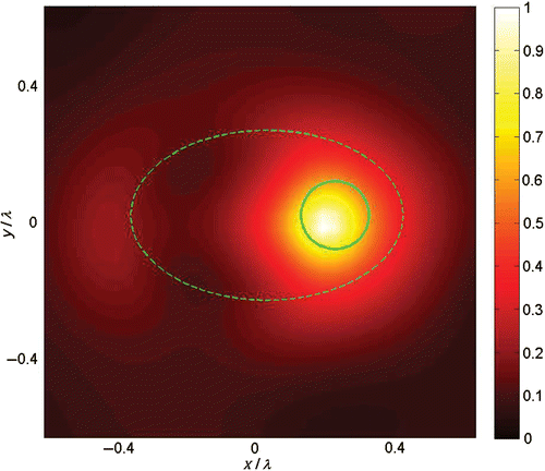
for each sampling point z in a grid 𝒵 covering T. In we show the visualization obtained by plotting
(rescaled to [0, 1]) as indicator function on a square domain T of side 1.4λ. We superimpose a dashed and a solid line to represent the true profiles of the background ellipse and of the circular scatterer, respectively: as expected, only the latter is visualized.
Figure 2. LSM-visualization (for far-field measurements) of a lossy circular scatterer (solid line) inside a lossy elliptic object (dashed line). (Available in colour online.)
The direct code and the LSM-algorithm provide a discretized version of the integrand in (26): then, for each z of interest, we can easily compute the field and the corresponding Poynting vector field
(cf. (13)) on an appropriate grid 𝒳 of points. Hence, for a given z ∈ 𝒵, the behaviour of the flow lines of
can be visualized by plotting the unit vector
on the points of 𝒳, where
is obviously obtained by normalizing
.
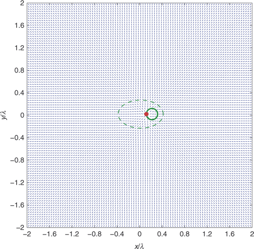
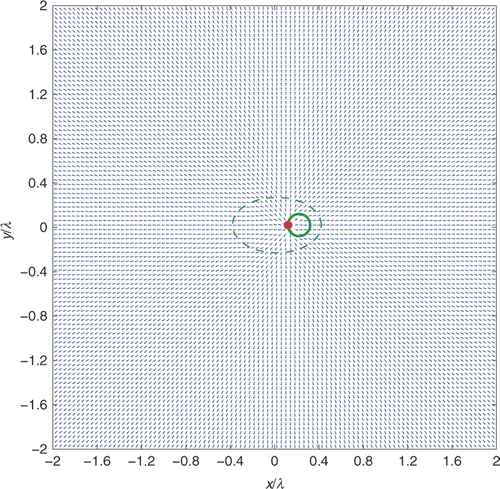
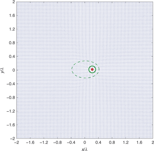
The typical behaviour of can be described as follows. When the sampling point z is taken inside the scatterer or even on its boundary ∂D, the flow lines are almost radially divergent from z itself, thus resembling the behaviour of the Green's function u(·, z) (cf. (4)) of the mere background: this situation is visualized in and . More precisely, both figures show the behaviour of the vector field
when the sampling point z is respectively chosen as either the centre of the circular scatterer or a point on its boundary. Moreover, analogous figures (not shown here) visualizing the normalized Poynting vector field associated with the Green's function u(·, z) for the same sampling points z turn out to be essentially identical to and . The circle Γ where the receivers are placed cannot be contained in these pictures, but no anomaly of the flow lines is observed when the visualization domain is extended up to the far-field region. In particular, the flow lines starting from ∂D are regular in the sense of Definition 4.1, and any z ∈ ∂D is a ramification point of
, i.e. a beam of several flow lines originates from z.
Figure 3. Behaviour of the vector field (for far-field measurements) when the sampling point z (red bullet) is taken inside the scatterer.
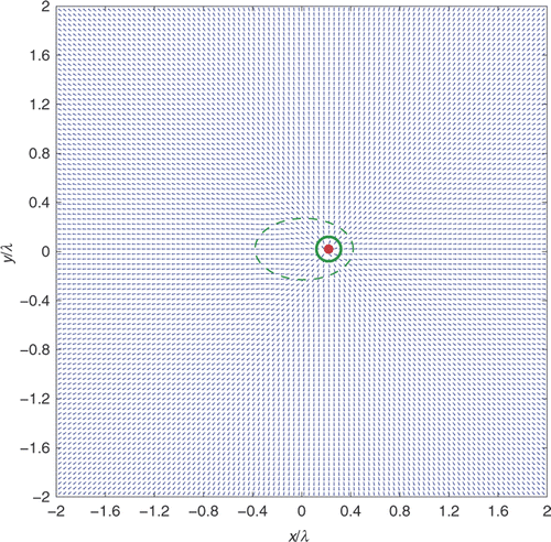
Figure 4. Behaviour of the vector field (for far-field measurements) when the sampling point z (red bullet) is taken on the boundary of the scatterer.
Let us briefly recall how this behaviour of the flow lines allows the conclusion that the L2[0, 2π]-norm of the approximate solution of Equation (21) must blow up as the sampling point z approaches a boundary point z* ∈ ∂D (for details, we refer to Citation12). Consider a sequence of points
such that limn→∞|zn − z*| = 0 and a corresponding sequence of collapsing circles
centred at z* and with radius
. Let
be the portion of the circle not contained in D, i.e.
, and let us assume that, for each n ∈ ℕ, the flow strip of
starting from
is regular, with non-vanishing far-field width as n → ∞, in the sense of Definition 4.1. If we assume, by contradiction, that the sequence
is bounded in L2[0, 2π], two contradictory facts can be proved. First, we can show that the power flux
across
vanishes as n → ∞, since the length
of the integration domain
tends to zero, while the integrand function remains bounded. Second, the same flux
must be greater than or equal to the far-field flux of the regular flow strip starting from
: but, according to inequality (25), by choosing ε small enough this far-field flux can be made arbitrarily close to that of the elementary source u(·; zn) across the same (non vanishing) far-field width of the flow strip. Then, by Assumption 4.1 and inequality (25), respectively, the far-field fluxes of both u(·; zn) and
are bounded from below by a positive constant, and then the same property holds for the near-field flux
. This contradiction is removed by dropping the hypothesis of boundedness for the sequence
.
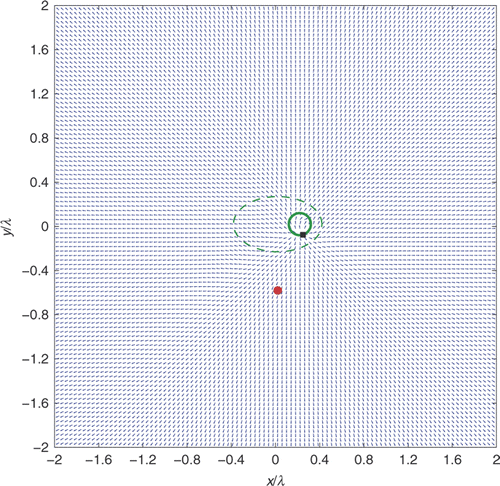
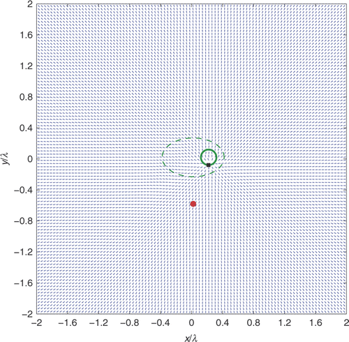
Now let us see what happens when the sampling point z is taken outside the scatterer D. The situation is shown in : the vector field by no means resembles the Poynting vector field associated with the background Green's function u(·, z). Moreover, a ramification point z0 of
is detectable on the boundary ∂D, as highlighted by the small black box on the boundary of the scatterer in .
Figure 5. Behaviour of the vector field (for far-field measurements) when the sampling point z (red bullet) is taken outside the scatterer: a ramification point (black box) appears on its boundary.
The behaviour of the flow lines outgoing from z0 suggests introducing the following definition.
Definition 5.1
The field ud defined in (7) is called partially pseudo-radial with respect to a ramification point z0 ∈ R if there exist at least two regular flow lines of ud, say and
, starting from z0 and with asymptotic polar angles
,
respectively, such that the flow strip delimited by them is regular with non-zero far-field width
. Moreover, if
is the set of the asymptotic polar angles of all such flow lines, we define the far-field width of this beam of flow lines as
.
We can now apply a contradiction argument very similar to the previous one, to conclude that, if ε is small enough, there cannot exist such that the field
is partially pseudo-radial with respect to a ramification point z0 ∈ R and inequality (22) is satisfied.
We point out that in both cases, i.e. for z → z* ∈ ∂D and for z ∉ D, the core of the argument is the fact that the far-field power flux outgoing from the regular flow strips of the field is bounded from below by a positive constant, and Assumption 4.1 (which is trivially verified in the framework of Citation12) is ultimately a way of ensuring this lower boundedness condition.
We can now summarize the above investigation by stating our version of the approximation Theorem 2.1: it is based on tracking the power loss in the flow strips of starting from the boundary of the scatterer and reaching the observation curve Γ, placed in the far-field region. This tracking is made possible by the behaviour of the flow lines, as observed in this section: in other terms, our theorem relies on some assumptions on the flow lines, but these assumptions do not follow from a theoretical investigation, but are rather the formalization of a numerically observed behaviour. In this sense, ours is an a posteriori approach. In spite of this limitation, the strong point of our new version of Theorem 2.1 is that any ε-approximate solution of the far-field equation (9) behaves as a good indicator function (i.e. its L2[0, 2π]-norm blows up as z approaches ∂D and when z ∉ D) for a small enough (but a priori non-vanishing) bound ε on the discrepancy
.
Theorem 5.2
Under Assumption 4.1 and the same hypotheses of Theorem 2.1:
| i. | let z* ∈ ∂D and let | ||||
| ii. | let z ∈ ℝ2 ∖ D: then, if ε is small enough, there does not exist | ||||
Proof
We shall adapt to the current framework the arguments proving Theorems 5.1 and 6.1 in Citation12.
| i. | Let z* ∈ ∂D and assume, by contradiction, that limit (28) is false. Hence, it is possible to find a constant K > 0 and a sequence | ||||
According to (7), for each n ∈ ℕ we have that , where
and
are defined in analogy with (26). By the same arguments used for the proof of Theorem 5.1 in Citation12, we can obtain uniform bounds for both
and
, as well as their derivatives. To this end, we recall that m(x) ≔ 1 − n(x) and Bm ≔ supp m; then, we also set
and
. Next, we define
, with R1 > 0 such that R1 < R0 (i.e.
, where
is defined soon below (1)) and
; finally, let
. Then, as explained in Citation12, there exists Q > 0 such that, for all n ∈ ℕ and for all
, the following inequalities hold:
(29)
Accordingly, the fields
and
remain bounded ∀n ∈ ℕ and
. As a consequence, we find
(30)
since the integral defining the flux (cf. (14)) is performed on a domain of vanishing measure, while the integrand function remains bounded.
On the other hand, if we track up to infinity the flux along the regular flow strip delimited by the two flow lines
and
of
, we find that the power outgoing from this flow strip in the far-field region is not greater than
, owing to the possible power loss along the path. Let us formally write this property: by using (14), (19), (25), (26) and assuming (with no actual restriction) that
, for each n ∈ ℕ we can write
(31)
Now, by hypothesis we have
; in particular, there exist ϕ1, ϕ2 ∈ [0, 2π], with ϕ1 < ϕ2, such that
for all n large enough, say n ≥ N. Then, from (31), Assumption 4.1 and taking
(32)
(with δ > 0 arbitrarily small), we easily find that there exists c > 0 such that
(33)
whence we have
, in contradiction with (30).
(ii) Let z ∉ D: by contradiction, we assume that there exist ε > 0 and such that inequality (27) is verified and the field
is partially pseudo-radial with respect to a ramification point z0 ∈ R. According to Definition 5.1, if ψ∞(z0) > 0 is the far-field width of the beam of flow lines outgoing from z0, there exists a regular flow strip delimited by two flow lines
,
starting from z0 and with asymptotic polar angles
,
respectively, such that the corresponding far-field width
is strictly positive.
Then, let {Cn(z0)}n∈ℕ be a sequence of circles centred at z0 and with radius rn, such that limn→∞rn = 0, and let us set for j = 1, 2. Accordingly, the intersection between the flow strip delimited by the flow lines
,
and the circle Cn(z0) identifies an arc
of extreme points
and
. Then, by the same arguments used in the proof of Theorem 6.1 in Citation12, we can prove that
(34)
As in the previous point (i), we can also track the power flux outgoing from up to the far-field region, by considering the regular flow strip delimited by the flow lines
and
of
starting from z0. Analogously to (31), we can write
(35)
We observe that the lower bound in (35) is now independent of n ∈ ℕ; moreover, since
, we have
by Assumption 4.1. Then, in order to obtain a contradiction between (34) and (35), it suffices to choose ε such that
(36)
This concludes the proof.▪
Remark 1
Theorem 5.2 deals with ε-approximate solutions of (21), then Tikhonov regularized solutions
are a particular case. Since
blows up only if α → 0, Theorem 5.2 foresees a vanishing α for z → z* ∈ ∂D and for z ∈ ℝ2 ∖ D. This is in qualitative agreement with the well-known behaviour of α in the LSM-algorithm: its values inside the scatterer are notably larger than those on its boundary or outside Citation2.
6. Power fluxes and the modified far-field equation: near-field measurements
It is now interesting to see how the above discussion on power fluxes can give an insight into the modified far-field equation (9) or, better, into its approximate version (10), for an observation circle Γ placed in the near-field region. Differently from the genuine far-field equation considered in Citation12, or from the case of far-field measurements as addressed in the previous section, at first sight inequality (10) seems to have nothing to do with power fluxes: indeed, as highlighted by definition (14), the power flux of any field involves both the field itself and its derivatives; on the other hand, having a control over the L2(Γ)-norm of a field, as is the case for (10), does not entail, in general, any control over its derivatives and, consequently, over its flux.
We can give an alternative description of the above difficulty. The most direct way for adapting the results of the previous section to the case of near-field measurements consists in the following two steps: first, one should assume the (near-field) regularity of the flow strips, in the sense of the following definition.
Definition 6.1
Given a point x1 ∈ {x ∈ ℝ2 : |x| < RΓ} ∖ D, a flow line of ud starting from x1 is called regular if
| i. |
| ||||
| ii. | ∃!τ1 > 0 such that | ||||
Second, it should be required that the power flux outgoing from the flow strips across their intersection with the observation circle Γ is bounded from below by a positive number. Nevertheless, the latter requirement is now very unnatural, since inequality (10) has a priori nothing to do with power fluxes.
In order to overcome this difficulty, we observe that the investigation domain T ⊂ ℝ2 where the sampling point can vary is a closed region surrounded by the circle Γ where the receivers are placed, i.e. . Accordingly, for each
and for every ε > 0, the radiating field (cf. definition (26))
satisfies the Helmholtz equation (with wavenumber k0) in
; moreover, it certainly holds that
. Hence, by virtue of Theorem 3.21 in Citation17, we can conclude that there exists a constant C such that
(37)
where
is the far-field pattern of
. Hence, having a near-field control over the L2(Γ)-norm of the latter field enables a control over the L2[0, 2π]-norm of its far-field pattern (while the converse is clearly false, cf. Citation17 and Remark 3.1 in Citation12). In particular, as seen in the previous section (cf. relations (19), (23) and (25)), we can make the total fluxes
and
as close to each other as we want, by choosing ε small enough. This observation has a twofold consequence.
First, if we choose [ϕ1, ϕ2] = [0, 2π], we have that the difference between the total fluxes and ℱ[0, 2π](u(·; z)) in the far-field region can be made arbitrarily small; but the observation circle Γ is placed in the outmost lossless region, then it holds that
and ℱ[0, 2π](u(·; z)) = ℱΓ(u(·; z)). Hence, inequality (10) entails a constraint on the two total power fluxes across Γ, whereby they must be close enough to each other. Note that equation (9), whence inequality (10) follows, is linear in the unknown
, while imposing a constraint directly on power fluxes, e.g. via the equation
, would give rise to a non-linear problem.
Second, if we consider the flow lines of the field beyond the observation circle Γ, i.e. up to the far-field region, the current framework becomes completely analogous to that of the previous section. Of course, Assumption 4.1 is now inelegant in that the detectability of the point source is required in the far-field region, while the measurements are made in the near-field. However, we can first replace Assumption 4.1 by its near-field analogous, i.e. by requiring that, for any circular portion Γ1,2 ⊂ Γ, there exists a constant c1,2 such that
for all z in the investigation domain T. Then, we can take into account the typical behaviour of the flow lines of the field u(·; z) radiated by a point source placed at z: although they are not exactly radial with respect to z, these flow lines typically spread out from z and are regular up to the far-field region. Accordingly, we can reasonably conclude that Assumption 4.1 is implied by its near-field analogous, owing to the conservation of the power flux carried by each flow strip through the lossless medium, i.e. from Γ to the far-field region.
Summarizing, the case of near-field observations can be made analogous to that of far-field measurements, as long as the flow lines of the scattered field are considered not only inside
, but also in all ℝ2, up to the far-field region. In particular, the near-field version of Theorem 5.2 is simply obtained by replacing inequality (27) with the more general (10).
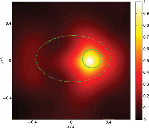
Then, as a last check, let us repeat the numerical experiment considered in Section 5, by only changing the radius RΓ of the observation circle Γ, which has now to be in the near-field region: we choose RΓ = 1.0 λ. The visualization provided by the LSM is given in and is almost identical to the previous one, plotted in .
Figure 6. LSM-visualization (for near-field measurements) of a lossy circular scatterer (solid line) inside a lossy elliptic object (dashed line). (Available in colour online.)
Then, Figures show the behaviour of the vector field for z ∈ D, z ∈ ∂D and z ∉ D, respectively, for the same sampling points considered in Figures : for each of the three corresponding pairs of pictures, an immediate comparison between the two images highlights that they are very similar. Hence, also from a numerical viewpoint, the case of near-field measurements can be discussed within the framework outlined for far-field measurements.
Figure 7. Behaviour of the vector field (for near-field measurements) when the sampling point z (red bullet) is taken inside the scatterer.
7. Conclusions
Our energy-based approach inspires a new form of the approximation theorem at the basis of the LSM. This reformulation provides a better explanation of the behaviour of the indicator function exploited by the LSM.
With respect to Citation12, the generalization is threefold: here the background can be inhomogeneous and/or lossy, while the receivers can also be placed in the near-field region. The inhomogeneity of the background implies that, a priori, the flow lines of the difference field ud = ũ s − us may have ramification points not only on the boundary ∂D of the scatterer, but also on any curve where the refraction index (x) is discontinuous. However (and interestingly), numerical simulations suggest that ramification points of
can only show up on ∂D, as if the corresponding difference
cancelled out the effect of all discontinuities of
(x) except that on ∂D: this sounds reasonable and in agreement with the idea of ‘subtracting the background’, which underlies the formulation of the LSM considered in this article.
The lossiness of the background implies that electromagnetic energy is not conserved any more along the flow strips of ud: however, the key arguments of Citation12 still hold by assuming that the absorption due to the imaginary part of n(x) is not too large, i.e. the presence of the elementary source in the investigation domain is always detectable by the receivers, in the sense of Assumption 4.1.
Finally, when the receivers are placed on a circle Γ in the near-field region, the modified far-field equation (9) cannot be directly regarded as a constraint on power fluxes, differently from the case of far-field measurements considered in Citation12 or in Section 4 (cf. (25)) of this article. However, having a control on the L2(Γ)-norm of a scattered field in the near-field region allows controlling the L2[0, 2π]-norm of its far-field pattern (cf. (37)): accordingly, taking into account the flow lines of the field up to the far-field region, the whole framework can be traced back to the far-field case.
Further developments concern both theoretical and numerical issues. From the theoretical viewpoint, a major achievement would consist of predicting the key-features (regularity, ramification points, etc.) of the flow lines, starting from the knowledge of the scattering conditions: this would make our physical interpretation a mathematical justification of the LSM. From a numerical viewpoint, it is interesting to investigate how much the LSM-algorithm (which accounts for discretization, noise, regularization, etc.) deviates from the continuous and noise-free framework. For example, our Theorem 5.2 requires that ε is small enough: indeed, depending on z, ε must be less than some upper bounds related to the far-field widths of appropriate flow strips (cf. inequalities (32) and (36)). On the other hand, such theoretical bounds have a priori nothing to do with the numerical values of the discrepancy as computed in the LSM-algorithm by means of Morozov's discrepancy principle: then, it would be interesting to check whether these values are consistent with their corresponding upper bounds. The investigation pursued in the simpler framework of Citation12 supports this consistency, but a more general and methodical approach to this problem is still missing.
Acknowledgments
Massimo Brignone was supported by a grant from the Istituto Nazionale d'Alta Matematica (INdAM), Roma, Italy.
References
- Colton, D, and Kirsch, A, 1996. A simple method for solving inverse scattering problems in the resonance region, Inverse Probl. 12 (1996), pp. 383–393.
- Colton, D, Piana, M, and Potthast, R, 1997. A simple method using Morozov's discrepancy principle for solving inverse scattering problems, Inverse Probl. 13 (1997), pp. 1477–1493.
- Colton, D, Haddar, H, and Piana, M, 2003. The linear sampling method in inverse electromagnetic scattering theory, Inverse Probl. 19 (2003), pp. S105–S137.
- Cakoni, F, and Colton, D, 2003. On the mathematical basis of the linear sampling method, Georg. Math. J. 10 (3) (2003), pp. 411–425.
- Cakoni, F, and Colton, D, 2006. Qualitative Methods in Inverse Scattering Theory. Berlin: Springer; 2006.
- Cakoni, F, and Colton, D, 2005. Open problems in the qualitative approach to inverse electromagnetic scattering theory, Europ. J. Appl. Math. 16 (2005), pp. 411–425.
- Kirsch, A, 1998. Characterization of the shape of a scattering obstacle using the spectral data of the far-field operator, Inverse Probl. 14 (1998), pp. 1489–1512.
- Kirsch, A, and Grinberg, N, 2008. The Factorization Method for Inverse Probl.. New York: Oxford University Press; 2008.
- Arens, T, 2004. Why linear sampling works, Inverse Probl. 20 (2004), pp. 163–173.
- Arens, T, and Lechleiter, A, 2009. The linear sampling method revisited, J. Integral Eqns Appl. 21 No. 2 (2009), pp. 179–202.
- Hanke, M, 2008. Why linear sampling really seems to work, Inverse Probl. Imag. 2 (2008), pp. 373–395.
- Aramini, R, Caviglia, G, Massa, A, and Piana, M, 2010. The linear sampling method and energy conservation, Inverse Probl. 26 (2010), p. 055004.
- Colton, D, and Monk, P, 1998. A linear sampling method for the detection of leukemia using microwaves, SIAM J. Appl. Math. 58 (3) (1998), pp. 926–941.
- Cakoni, F, Fares, M, and Haddar, H, 2006. Analysis of two linear sampling methods applied to electromagnetic imaging of buried objects, Inverse Probl. 22 (2006), pp. 845–867.
- Cakoni, F, 2007. Recent developments in the qualitative approach to inverse electromagnetic scattering theory, J. Comput. Appl. Math. 204 (2007), pp. 242–255.
- Rizvi, AA, and Papas, CH, 2000. Power flow structures in two dimensional electromagnetic fields, Prog. Electromagn. Res. 29 (2000), pp. 261–294.
- Colton, D, and Kress, R, 1998. Inverse Acoustic and Electromagnetic Scattering Theory, . Berlin: Springer; 1998.
- Harrington, RF, 2001. Time-Harmonic Electromagnetic Fields. New York: IEEE Press, John Wiley & Sons; 2001.
- Stutzman, WL, and Thiele, GA, 1981. Antenna Theory and Design. New York: John Wiley & Sons; 1981.
- Richmond, JH, 1965. Scattering by a dielectric cylinder of arbitrary cross section shape, IEEE Trans. Ant. Prop. 13 (1965), pp. 334–341.
- Ramananjaona, C, Lambert, M, and Lesselier, D, 2001. Shape inversion from TM and TE real data by controlled evolution of level sets, Inverse Probl. 17 (2001), pp. 1585–1595.
