Abstract
In this article, a nullor approach to analogue circuit diagnosis at subcircuit and at component levels is developed. The test voltages of the accessible nodes and the current through the voltage supply are selected as test quantities. A nullor diagnosis model of the circuit under test is constructed. The automated fault localization and identification of single and multiple faults is reduced to simulation of a nullor diagnosis model. The approach allows us to automatically carry out fault identification of soft (parametric) faults using standard circuit simulators. Based on the simulation of the diagnosis model of the faulty circuit, fault coverage investigation and optimal test node selection can be performed in order to increase the testability of the circuit. An example illustrating the proposed approach is presented.
1. Introduction
The fault diagnosis is a very important problem of analogue circuit testing. Localization of faulty elements and determination of the changed parameter values using measurement data for the test voltages of the faulty circuit represent a typical inverse problem. The increasing complexity of the analogue and mixed-signal VLSI circuits, the limited number of accessible nodes and the lack of efficient fault models complicate the fault localization and fault identification.
A number of techniques for analogue fault diagnosis have been proposed, but a fully automatic diagnosis approach has not yet been developed for circuits having different types of faults, modes of operation, as well as different test quantities. Many approaches have been developed to automate diagnosis of analogue and analogue-discrete circuits before and after test: model-based approaches [Citation1,Citation2], branch decomposition diagnosis at subcircuit and component levels [Citation3,Citation4], fault dictionary techniques, sensitivity-based, symbolic, spectral, neural network, optimization approaches [Citation5–7], etc. The sensitivity analysis is applied in Slamani and Kaminska [Citation7] for optimal test frequency selection in order to increase the fault observability and to avoid fault equivalence and fault masking. The fault identification in circuits of analogue-discrete type such as switched-capacitor circuits is considered in Farchy et al. [Citation8]. The effectiveness of the optimization techniques for circuit diagnosis, such as genetic algorithms, depends on the possibility of using accurate computer models for the circuit elements.
The monitoring of the IDD current offers the opportunity to perform reliable diagnosis of faulty circuits with insufficient number of accessible (test) nodes. It is assumed in analogue circuit diagnosis that there is no parametric fault cancellation. Different methods are proposed to improve the diagnosis results from the IDD testing [Citation9,Citation10]. The design-for-test technique for analogue circuits [Citation9] splits all high current transistors into two. This technique reduces the fault-masking effects of the fault-free parts of the circuit, giving a potential fault cover of over 99%. The method using magnitude and phase spectrum components for fault detection of catastrophic and parametric faults [Citation10] allows us to improve the fault coverage by the use of the power supply current against the output voltage signal.
The concept for the pair fixator (nullator plus source) and norator is used in the diagnosis model approach proposed in Farchy et al. [Citation4]. A nullator–norator (nullor) based DC-test generation approach is developed in Straube and Vermeiren [Citation11]. A nullor network diagnosis using multilayer perceptron is proposed in Nenov et al. [Citation12]. The topological conditions for diagnosability investigation using graphs containing nullators and norators are considered in Hernandes-Martinez and Sarmiento-Reyes [Citation13]. The nullor concept is applied to automated analogue active circuit design [Citation14]. A bibliography on research work related to nullors and their applications in circuit analysis, synthesis and design is given in Kumar and Senani [Citation15].
The contemporary general purpose analogue circuit analysis programs such as PSpice are characterized by powerful analysis tools which allow us to perform accurate and fast simulation. Adequate models of the electronic elements are included in the computer libraries. The abilities of the input languages allow us the construction of user-defined computer models. These extended possibilities of the circuit simulators motivate the development of analogue circuit diagnosis approaches in the environment of the contemporary CAD systems. In this way, the construction and solving of the test equations is reduced to analysis of corresponding diagnosis model. In addition, the tolerance (Monte Carlo and worst case) analysis tools can be used in order to take into account the design tolerances and to automatically determine the non-faulty limits for the test quantities.
In this article, a nullor approach to analogue circuit diagnosis at subcircuit and at component levels is developed. The diagnosis technique proposed solves the inverse problem for the fault localization and for obtaining the faulty parameter values of the circuit components and is based on measurements of test voltages at the accessible nodes and the current IDD through the voltage supply. A nullor diagnosis model of the circuit under test is constructed and analysed. The automated fault localization and identification of single and multiple faults is reduced to simulation of the nullor diagnosis model.
2. Diagnosis model
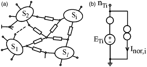
The circuit under test N shown in consists of subcircuits S1, S2, … , Sl and branches in the main circuit (links). The nodes nT1, nT2, … , nTm in N are accessible for measurement of the voltages VT1, VT2, … , VTm (test voltages), where m is the number of accessible (test) nodes. The voltage supply current IDD is also accessible for testing.
Figure 1. Circuit under test N with accessible nodes (a) and nullor model for testing the accessible node i (b).

The localization of the faulty links and subcircuits is performed using testing of the accessible nodes, which is based on analysis of nullor diagnosis model Nd of the tested circuit [Citation4]. The Nd model is obtained from the model Nnom of the nominal circuit applying the measured test voltages VTi of the faulty circuit to the test nodes nTi = 1, 2, … , m using independent voltage source ETi = VTi connected in series with a nullator (voltage fixator) (). The role of the fixators is to apply the measured test voltages to corresponding accessible nodes. The role of the norators is to ensure path for the difference currents due to the fault.
According to its definition, the nullator element is characterized by i = u = 0 [Citation16]. As a result, the test voltage VTi, corresponding to a faulty circuit, is applied to the corresponding test node nTi. The correctness of the node nTi is tested by connecting a norator between the node nTi and the reference node () [Citation4]. The norator ensures a path for the difference current Inor,i flowing as a result of faults in subcircuits or links connected to the test node nTi. If Inor,i = 0, the node nTi is non-faulty. The subcircuit Sk is non-faulty, if all its poles are non-faulty nodes. A link is correct if it is incident to at least one non-faulty node [Citation4]. The rest of the elements are potentially faulty.
The topological conditions for existence of a unique solution of the nullator–norator diagnosis model are discussed in Farchy et al. [Citation4] and Hernandes-Martinez and Sarmiento-Reyes [Citation13]. The circuit containing nullators and norators has a unique solution if the structural graph of the circuit G contains two trees T1 and T2, where the tree T1 includes all nullators but does not include norators, while the tree T2 includes all norators but does not include nullators.
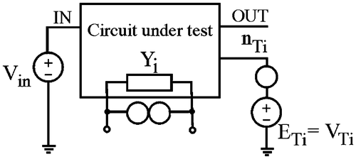
The testing of the eventually faulty elements is performed using the nullor model shown in . In order to test a k-fold fault, the test voltages VTi are applied to the test nodes nTi, i = 1, 2, … , k and the norator element is connected in parallel with the tested element Yi, i = 1, 2, … , k. The correctness of the remaining nT = m − k test nodes is checked using the nullor equivalent circuits shown in . The number of the test nodes defines the maximal multiplicity of tested faults.
The nullor approach can be applied to fault diagnosis, if test voltages and test IDD current in the frequency, DC and time domain are employed. The diagnosis in the time domain permits to define additional measures based on transient response, oscillation signals, as well as on their spectral components.
The measure can be defined in the form:
(1)
If , a k-fold fault is localized in the tested group. If
, at least one faulty element is not included in the tested group. Similarly, based on monitoring of the voltage supply current IDD, the measure
can be defined for the faulty element testing. It is defined in the form
(2) where
is the measured voltage supply current of the circuit under test and
is the voltage supply current of the diagnosis Nd model.
The changed parameter value of the localized faulty element Yi is obtained from the simulation results of the Nd model. The difference
is calculated by way of its component equation using the voltage VYi and the current Inor,i.
The fault diagnosis at subcircuit level is reduced to testing corresponding subcircuit poles using the nullor model shown in . This approach is also used to test active components (transistors, operational amplifiers, etc.).
The diagnosis algorithm consists of the following steps:
| 1. | decomposition of the circuit to a number of subcircuits which poles coincide with the accessible (test) nodes; | ||||
| 2. | carrying out diagnosis of the accessible nodes and subcircuits. If all poles of a subcircuit Si are non-faulty nodes, the subcircuit is correct. Otherwise, it is considered faulty; | ||||
| 3. | carrying out diagnosis of the elements in the faulty subcircuits using the pairs fixator–norator, as shown in ; | ||||
| 4. | calculating the measures (1) and (2) and localize the faulty elements in the tested group, which is characterized by minimal values of the measures. As a result, the nullor approach allows us to test also the elements connected to inaccessible nodes. | ||||
3. Assessment of the design tolerances
It is of significant importance to assess the influence of design and process tolerances in the diagnosis procedure. The non-faulty limits for the measures (1) and (2) are used to distinguish the tolerance deviation from a fault. Monte Carlo simulation is performed of the nominal circuit with tolerances Nnom,tol together with the Nd model, where the voltages VTi of the Nnom,tol circuit are applied to the test nodes of Nd model using fixators. As a result, the non-faulty limits for the measures and
are obtained.
In the diagnosis stage, the measured test voltages of the faulty circuit are applied to the test nodes of the Nd model and the measures (1) and (2) are calculated. If these measures are within their non-faulty limits, a fault is localized in the tested group; otherwise, a fault exists in another element.
In order to improve the diagnosis results, a fault prediction approach can be applied to reduce the influence of the design tolerances. As proposed in Jiang et al. [Citation17] prediction algorithm, the component values are evaluated according to the consecutive voltage measurements that are continuously monitored at the accessible test points at each periodic maintenance. Based on this approach, a difference diagnosis nullor model is constructed. Instead the measured test voltages VTi, the differences between two successive measured test voltages are applied to the test nodes nTi by fixators. In this way, the influence of the design tolerances is significantly reduced.
4. Computer implementation of the diagnosis approach
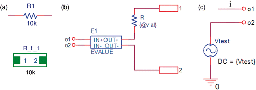
The nullor element can be approximately represented in the input language of the general purpose circuit simulators by a dependent source having a large value of the gain. The nullor element in can be efficiently modelled by the PSpice circuit simulator [Citation18] using a dependent current or voltage source, controlled by voltage (voltage controlled current source (VCCS) or voltage controlled voltage source (VCVS)), with a large controlling coefficient, for example 1 1012. The PSpice implementation using VCCS of GVALUE type is presented in . The implementation using VCVS of EVALUE type is presented in . The corresponding properties of the elements are also given. The nullor as a part of the pair fixator–norator, can also be easily modelled in the PSpice program by an ideal OP AMP, which is included in the symbol and model libraries.
Figure 3. Computer model of the nullor: (a) nullator–norator pair (nullor); (b) PSpice model of the nullor using VCCS and (c) PSpice model of the nullor using VCVS.

The computer realization of the diagnosis model used for testing of the faulty resistor () is presented in . It is defined in the form of a parametrized hierarchical block. The VCVS E1 is equivalent to a nullor. Its description in the Expression field has the following form:
The parameter par is varied linearly from 1 to NF with an increment of 1, where NF is the number of tested faults. When the parameter par is equal to the ID number num of the element, the value of the VCVS gain is 1 1012 and the norator is connected to the tested element, otherwise the gain is 0 and the norator is not connected to the element. The diagnosis models of the faulty capacitor and faulty inductor are created in a similar way connecting VCVS E1 in series with the corresponding element. If VCCS is used for the nullor model realization (), it is connected in parallel with the tested element. The description in the Expression field is the same as for VCVS.
The measured test voltage of the faulty circuit is applied to the test node using the series connection of a nullator and voltage source (fixator) shown in . The computer realization using the independent voltage source Vtest is shown in .
The proposed diagnosis approach allows us to reduce the fault location and the fault identification to parametric analysis of the diagnosis nullor model.
The effectiveness of the nullor diagnosis approach depends on the number of required simulations as well as on the speed of simulation. The nullor approach to fault localization requires NF simulations of the diagnosis model. This number is less than the number of simulations required by the model-based approaches, where simulations with and
deviations from the nominal value are performed for each tested elements.
The implementation of the nullor diagnosis approach in standard circuit simulators such as Cadence PSpice allows us to avoid the construction and solving diagnosis sets of equations used in decomposition matrix approaches. The sparse matrix approach used in contemporary analysis programs leads to computational efficiency of the approach. The possibility for accuracy and convergence control allows us to diagnose circuits consisting of subcircuits with a large number of inner (inaccessible) nodes.
An important advantage of the nullor diagnosis approach in comparison with the decomposition approaches is that it is realized using standard PSpice-like circuit simulators, as a part of the contemporary CAD packages. These simulators are based on sparse matrix approach and modified nodal analysis, which permits us to achieve a high speed of simulation for circuits having a large number of nodes. Based on Monte Carlo simulation, the design and process tolerances of the circuit elements are taken into account in order to obtain the non-faulty limits of the norator currents.
One of the most important advantages of the realization of diagnosis approach in the environment of standard circuit simulators consists in the use of accurate computer models of electrical and electronic elements. This allows us to obtain adequate diagnosis results. For example, the diagnosis of RF circuits is based on the measured phasors of the S-parameters, introduced using fixators in the diagnosis model. High-frequency models of passive and active components are submitted by the vendors in the form of model and symbol libraries for Cadence Capture and Cadence PSpice (http://www.cadence.com/products/orcad/pages/downloads.aspx#models). Libraries for RF MOSFETs, HBT, RF bipolar transistors, planar inductors on chip, etc. are accessible for the user. The inclusion of models for submicrometre transistors extends the possibilities for accurate simulation, design and diagnosis of large analogue IC.
5. Computer diagnosis of the example circuit
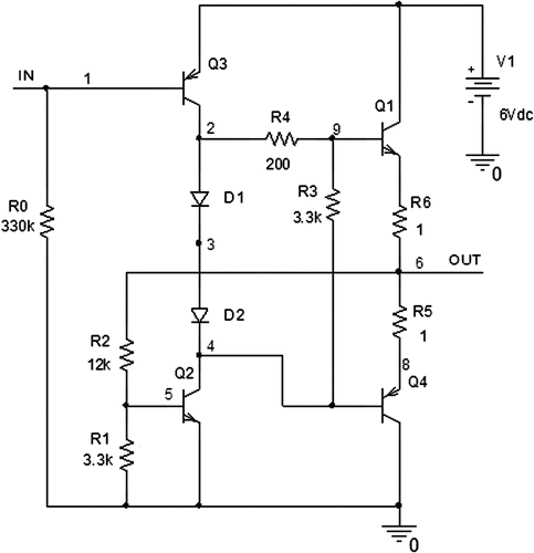
The benchmark circuit shown in [Citation6] is used to illustrate the computer-aided diagnosis based on DC test voltages [V2, V3, V4, V5] and on the IDD test current. The parametric fault localization of the elements is performed using parametric bias point simulation of the diagnosis model Nd of the circuit under test.
The measures and
are obtained using the following macrodefinitions of the graphical analyzer Probe:
In order to obtain the non-faulty limits of the tested quantities, the design tolerances of 5% are defined with uniform distribution for the parameters of the circuit elements and Monte Carlo analysis of the nominal circuit is performed. As a result, the non-faulty limits [IDD,min, IDD,max] of the voltage supply current IDD and of the measures and
are obtained. They are shown in and , respectively.
The measures and
are calculated for each value of the parameter par and the element corresponding to a minimal value of the measure is selected (). For example, when a single parametric fault in R2 exists (R2 + 100%), the measures
and
have minimal values for par = 4, corresponding to connection of a norator to R2. Hence, the faulty element R2 is localized. The changed parameter value of the faulty element Rd is obtained from the simulation of the diagnosis model: Rd = V12/IR (). For the element R2, V12 = 4.6665 V and IR = 0.19444 mA. As a result, the faulty value R2d = 24 k
(R2 + 100%) is identified.
The single fault in R3 (R3 + 50%) is detected, corresponding to minimal values of the measures and
for par = 6 corresponding to connection of a norator to R6, as shown in . In this case, V12 = 1.146 V and IR = 0.2315 mA () and the faulty value R3d = 4.95 k
(R3 + 50%) is identified. Taking into account the design tolerances, the fault in R2 is recognized with a minimum value for par = 4:
[A] and
, which are within the tolerance fields for
and
( and ). The obtained results are in agreement with the diagnosis of the benchmark circuit [Citation6] applying genetic algorithm.
6. Conclusions
A nullor approach to parametric fault diagnosis in analogue circuit has been proposed. A nullor diagnosis model of the circuit under test is constructed. The automated fault localization is reduced to simulation of a nullor diagnosis model. The conditions for testing the correctness of the subcircuits are given. Computer models are developed for testing the faulty nodes and faulty elements. Parametrized models of the faulty components are proposed based on IF-THEN-ELSE description. Different kinds of test quantities – test voltages and test IDD current can be used in the faulty element models. The faults are localized using parametric analysis. Measures are defined for testing the faults using norator currents and using the voltage supply IDD current. The influence of the design tolerances is taken into account to obtain the non-faulty limits of IDD and the norator currents.
References
- Mozetic, I, Holzbaur, C, Novak, F, and Santo-Zarnik, M, 1995. Model-based analogue circuit diagnosis with CLP(R), in Proceedings of 4th International GI Congress, Munich, Germany, W. Brauer, ed.. Berlin: Springer-Verlag; 1995. pp. 343–353.
- Dimitrova, E, Gadjeva, E, Bossche, AVan den, and Valchev, V, 2006. A Model-based Approach to Automatic Diagnosis Using General Purpose Circuit Simulators. Vol. 4. Montreal, Quebec, Canada: in IEEE International Symposium on Industrial Electronics – ISIE 2006; 2006. pp. 2972–2977.
- Salama, AE, Starzyk, JA, and Bandler, JW, 1984. A unified decomposition approach for fault location in large analog circuits, IEEE Trans. Circuits Syst. 31 (1984), pp. 609–622.
- Farchy, S, Gadzheva, E, Raykovska, L, and Kouyoumdjiev, T, 2006. Nullator-norator approach to analogue circuit diagnosis using general-purpose analysis programmes, Int. J. Circuit Theory Appl. 23 (6) (2006), pp. 571–585.
- Lin, TC, Kuo, MJ, and Chen, YC, , Frequency Domain Analog Circuit Fault Diagnosis Based on Radial Basis Function Neural Network, VLSI Design/Cad Symposium, Taiwan, 2007.
- Rutkowski, J, and Golonek, T, 2001. Application of Genetic Algorithms to Analog Fault Diagnosis. Vol. 1. Espoo, Finland: in European Conference on Circuit Theory and Design – ECCTD'01; 2001. pp. 253–256.
- Slamani, M, and Kaminska, B, 1996. Fault observability analysis of analog integrated circuits in frequency domain, IEEE Trans. Circuits Syst. 43 (1996), pp. 134–139.
- Farchy, S, Gadjeva, E, and Kouyoumdjiev, T, 1998. Fault Identification in Analog-discrete Circuits Using General-Purpose Analysis Programs. Vol. 1. Lisbon: in IEEE International Conference on Electronics, Circuits and Systems; 1998. pp. 495–498.
- Chalk, CD, and Zwolinski, M, 1997. A design for test technique to increase the resolution of supply current monitoring in analogue circuits, Electron. Lett. 33 (21) (1997), pp. 1746–1748.
- Papakostas, D, and Hatzopoulos, A, 2004. Analogue fault detectability comparison between power supply current and output voltage magnitude and phase spectrum components, Electron. Lett. 40 (8) (2004), pp. 457–458.
- Straube, B, and Vermeiren, W, 2002. A nullator-norator-based Analogue Circuit DC-test Generation Approach. Montreux, Switzerland: 8th International Mixed-Signal Testing Workshop; 2002. pp. 133–136.
- Nenov, G, Sotirov, S, and Nenova, M, 2003. Nullor Network Diagnosis by Using Multilayer Perceptron. Vol. 1. IEEE Conference EUROCON 2003. Computer as a Tool; 2003. pp. 67–70.
- Hernandes-Martinez, L, and Sarmiento-Reyes, A, 2003. Topological considerations for the diagnosability conditions of analogue circuits using a pair of conjugate trees, J. Electron. Test.: Theory Appl. 19 (2003), pp. 29–36, Kluwer Academic.
- Hashemian, R, 2008. "Local biasing and the use of nullator-norator pairs in analog circuits designs". In: Proceedings of the Midwest Symposium on Circuits and Systems. Knoxville, TN. 2008. pp. 466–469.
- Kumar, P, and Senani, R, 2002. Bibliography on nullors and their applications in circuit analysis, synthesis and design, Analog Integr. Circuits Signal Process. 33 (2002), pp. 65–76, Kluwer Academic.
- Carlin, H, 1964. Singular network elements, IEEE Trans. Circuit Theory 11 (3) (1964), pp. 67–72.
- Jiang, BL, Wey, CL, and Fan, LJ, 1988. Fault prediction for analog circuits, J. Circuits Syst. Signal Process. 7 (1) (1988), pp. 95–109.
- PSpice Reference Guide, Cadence PCB Systems Division, USA, 2000.


