Abstract
An estimation of the velocity field in a 2D section of an anisotropic homogeneous soil dike, using internal temperature measurements, is proposed here. Non-linear-Kalman-filter-based inversion algorithms are applied on the advection-diffusion equation coupled with Darcy's equation in this dike, which is considered as a porous medium with variable saturation. A sensitivity study shows that for large enough seepage rates the thermal behaviour of the dike is purely advective in the horizontal direction, because of the anisotropy of the dike: the horizontal hydraulic conductivity is the main physical parameter that governs the velocity field in this porous medium. As a consequence, a reduced one-dimensional model is used for inversion. It is tested on simulated and real measurements (the unknown initial temperature distribution can also be estimated).
Nomenclature
| T | = | temperature, K |
| = | Darcy's velocity of water, m s−1 | |
| C | = | heat capacity, J K−1 kg−1 |
| Kh, Kv | = | horizontal and vertical hydraulic conductivities, m s−1 |
| K | = | relative permeability of water |
| S0 | = | storage compressibility, m−1 |
| S | = | saturation |
| Λ | = | thermal dispersion tensor, W m−1 K−1 |
| ψ | = | hydric potential, m |
| ϵ | = | porosity |
| ρ | = | density, kg m−3 |
| αL, αT | = | longitudinal and transverse thermo-dispersivities, m |
| t | = | transpose |
| s | = | soil matrix |
| w | = | water |
| f | = | final |
| r | = | residual |
| s | = | saturation |
| h | = | horizontal |
| v | = | vertical |
| L | = | longitudinal |
| T | = | transverse |
1. Introduction
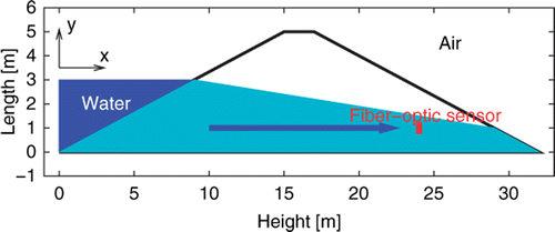
Detection of possible leakages of a canal through water seepage through the soil dike, as well as their quantitative evaluation in real time, is the cause of major concern for a good canal management. Temperature measurements by fibre optic sensors over very large distances (several kilometers) are now possible: they provide information on the local state of the dike. In any cross section (), air temperature Tair, water temperature Twater inside the canal and local soil temperature Tdike inside the dike can be monitored this way during several months. Knowledge of intrinsic thermo-physical and hydro-geological properties of the constitutive soil material(s) of the dike is also available.
Figure 1. Cross section of canal and dike.
2. Physical state-space model
The temperature field in the dike is given by the one-temperature heat dispersion equation in a porous medium Citation1
(1)
with
the velocity given by Darcy's law
(2)
and the hydric potential ψ given by the law of mass conservation Citation2
(3)
Van Genuchten and Mualem represent the hydrodynamics properties S, the water saturation and K, the relative permeability of the water phase, by
(4)
This is an empirical model where H represents the Heaviside operator. The thermal dispersion tensor Λ is given by the following expression:
(5)
3. Boundary condition and numerical resolution
3.1. Boundary conditions
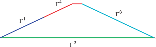
Before solving numerically the system of equations, it is necessary to introduce the boundary condition. gives the repartition of the boundaries.
Figure 2. Boundary conditions.
3.1.1. Richards' equation
The boundary conditions of Richards' equation is given by
(6)
where h corresponds to the height of the water in the canal. The first condition is a Dirichlet condition: the hydric potential, ψ, is equal to the height of the water h. A Neumann condition (second line) is chosen to represent the impermeability condition, and the last condition, called Signorini, represents the seepage properties: if ψ ≤ 0 then
(Neumann condition), otherwise ψ = 0 (Dirichlet condition).
3.1.2. Heat transfer equation
The boundary conditions of the heat transfert equation are given by
(7)
where Φ represents the heat exchange coefficient (Fourier condition).
3.2. Numerical schemes
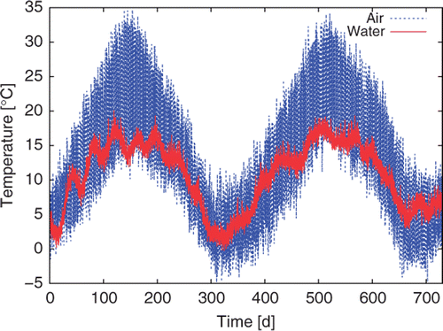
With these appropriate boundary conditions corresponding to air- and water- simulated temperature measurements during 2 years (), the previous equations have been solved numerically by a P1, the finite element method in 2D space, and by the Crank–Nicholson discretization in time, implemented in a MatLab© code, where we supposed that leakage is established (i.e. ∂tψ = 0). The results are compared with the output of Comsol© and FeFlow© Citation2, commercial softwares.
Figure 3. Recording of air and water temperatures.
4. Results of simulations and sensitivity study
The corresponding simulation of water flow and heat transfer in a soil with different hydraulic conductivities is shown in , in order to study the influence of hydraulic conductivity on the temperature at a point located in (xs = 24 m, ys = 1 m). These results have been verified by comparing the output with Comsol© and FeFlow© commercial software.
Figure 4. Sensitivity of the temperature at the sensor location to hydraulic conductivity.
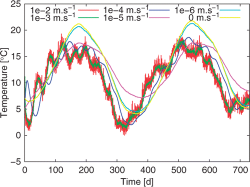
We note that the temperature simulated at the sensor location in the dike and the water temperature, (), show similar behaviour: the amplitudes of their variations are very close, for hydraulic conductivities between 10−2 m s−1 and 10−3 m s−1, but their phases are a bit different. The dike can be considered as a low-pass filter for water. A 10−4 m s−1 hydraulic conductivity yields a similar thermal behaviour with a larger phase shift (low-pass filter with a smaller cut frequency).
Analyzing the results for a 10−5 m s−1 hydraulic conductivity is more involved: the phase difference between the dike and the air temperatures becomes very small with a larger attenuation for the variations of dike temperature. This damping may stem from the influence of water on the dike sensor.
Of course, a lower conductivity (10−6 m s−1 or less) reduces the influence of water on the dike: sensor temperatures become almost the same as the air one.
gives the maximum velocity and the Péclet number (Pe = (ρC)wvxL/Λxx) for different hydraulic conductivities and for ϵ = 0.3, Sr = 0.226, Ss = 1, (ρC)w = 4.68.10−6 J m−3 K−1, (ρC)s = 2.1.10−6 J m−3 K−1, λw = 0.6 W m−1 K−1, λs = 2.9 W m−1 K−1, αL = 0.2 m, αT = 0.02 m, L = 32 m, Kv = Kh/100, n = 1.41, m = 1 − 1/n, α = 2 m−1 and Φ = 10 W m−1 K−1. The Péclet number allows an evaluation of the relative influences of diffusion and advection in the transfer of heat: it is the ratio between the advection term (caused here by water seepage through the dike) and the diffusion term in the heat equation: it is thus related to the influence of either water or air on the dike temperature.
Table 1. Characteristic values for different hydraulic conductivities.
We see that the higher the hydraulic conductivity of the dike is, the better the quality of velocity estimation becomes: this can be numerically observed in our results.
5. Inverse problem
The inverse problem considered here consists in estimating physical parameters (hydraulic and thermal) of a porous medium by the observation of partial data: water, air and sensor-in-the-dike temperatures.
Inverse problem can be resolved in many different ways. Variational methods consist in minimizing the L2 distance between prediction (provided by the model) and observation (provided by the sensor) during a predefined temporal window, whereas sequential methods, or observing methods, update the estimation with each new available partial observation. For our problem, we choose a sequential method, because a real time estimation is required.
In this section, a series of Kalman's filters of different types Citation3 is considered. The Kalman filtering is made in two steps. First, prediction provides a deterministic model, and then thanks to the difference between model and observation, a correction can be computed. Implicitly, the Kalman's filter minimizes the cost function:
(8)
where yn represents the observation at time tn, Xn the state of the system, that is looked for, and H is the operator linking observation and state.
In order to avoid an inverse crime, Citation4, our algorithm is tested, for a homogeneous medium case with data computed with FeFlow©.
5.1. Assumptions and parameter estimation
Before testing the inversion algorithm, we must define the parameter to be estimated. The velocity field in the dike is looked for, but one can wonder under which form it can be parameterized. The Richards equations, (2) and (3), provide information about the field, but their implementation requires an a priori knowledge of the hydraulic and thermal parameters. The assumption of a stationary flow is made here, because the time required for the development of a leakage is much smaller than the thermal diffusion time.
We observed through simulation and a sensibility study in Section 4 that temperatures of water and at the sensor location are similar for high hydraulic conductivities. In that context, the diffusive term can be ignored and the heat equation turns out to be nearly purely advective (see Péclet number values in ). Thus, precise knowledge of ϵ, (ρC)w, (ρC)s, λw, λs, αL and αT is not necessary, since these parameters have no significant influence on the results.
The parameter with larger effect on the ground temperature is the hydraulic conductivity Kh (Kv/Kh ∼ 1/100), so it has been decided to estimate it. This parameter is an intrinsic characteristic of soil and its estimation can only be done in a leakage context. Without a leakage, we wish our algorithm to return to the value 0 (a dry ground implies a null velocity field according to Darcy's law). Physically speaking, this is wrong, as hydraulic conductivity is not equal to zero, otherwise, no leakage could be possible. Consequently, we prefer to speak of an apparent hydraulic conductivity. In the context of a leakage, hydraulic conductivity will be estimated first, using Kalman's estimation algorithms, and velocities will be computed afterwards, as an output of the model.
5.2. Kalman's filter for a 2D model
5.2.1. Extended Kalman's filter
Extended Kalman's filter principle is the same as linear Kalman's filter, but the system needs to be linearized in the neighbourhood of the current prediction. This filter is theoretically under-optimal and does not warrant convergence and stability. Results, in terms of convergence of the estimated hydraulic conductivity Kh, are shown in , for an exact value Kh = 10−3 m s−1. After 50 days or more, a good estimation of hydraulic conductivity is reached. If one looks at the early time steps (days), after 3 or 4 days, the system matrix becomes well-conditioned and the algorithm begins to converge. However, construction of matrices of model noise and measurement noise are quite involved.
5.2.2. SEEK's filter: singular evolutive extended kalman's filter
Many versions of the filter are available for reducing the computation cost. Pham et al. Citation5 study a new Kalman's filter introduced by Moireau et al. Citation6 for data assimilation in oceanography problem, called singular evolutive extended Kalman's filter. The singularity of this filter comes from the ‘correction direction’ evaluated with the dynamical system.
Results, shown in , are less precise than the ones of the extended Kalman's filter, but adjusting noise matrices is easier and a more stable algorithm is obtained. The convergence needs few hours to be achieved.
5.3. Extended Kalman's filter for a 1D model
It has been shown in Section 4 through a sensitivity study that the thermal behaviour becomes mainly advective, as soon as a high enough level for the apparent hydraulic is reached. Moreover, anisotropy of the dike makes the horizontal velocity dominant. So, for an inversion purpose, a physically reduced model, where the heat equation is written in a one-dimensional space frame, will be considered ().
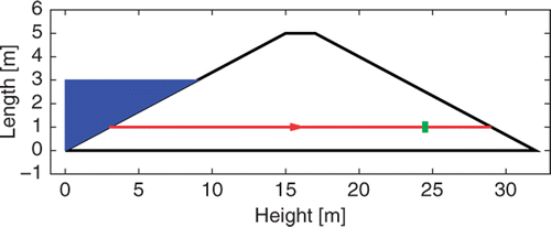
Figure 5. Reduced 1D model with horizontal stream line from water to sensor and air.
It brings the following advantages: first, the computing time is reduced by a factor larger than 100 to invert 2 years of data the effect of numerical noise is attenuated and the numerical scheme is more stable.
The reduced heat equation model is
(9)
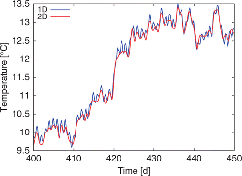
A numerical test (), using the same input parameters as Section 4, with Kh = 10−3 m s−1, confirms that the thermal behaviours at the sensor location are the very closed for the 1D and 2D models.
Figure 6. Comparison of temperature outputs of 1D and 2D models.
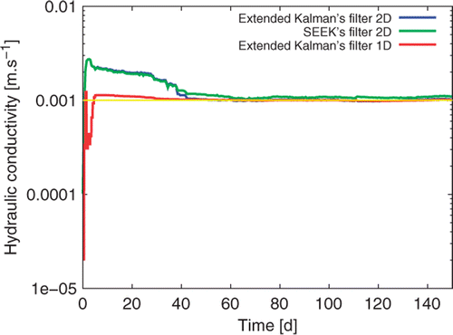
Results shown in are very promising for high seepage rate. We have no problem of convergence and the convergence is very fast. We do not test the SEEK's filter because we have only 30 points of spatial discretization.
Figure 7. Comparison of hydraulic conductivity estimation for different Kalman filters and 2D or 1D model.
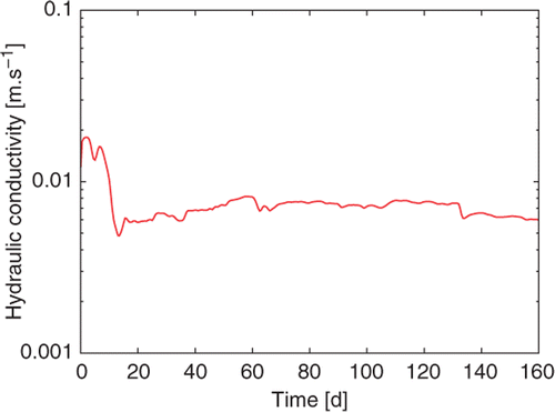
5.4. Inversion of real measured temperatures
Real recorded temperature data, shown in and corresponding to a silt dike with known leakage, have been inverted using the extended Kalman filter based on the reduced 1D model. As in the simulated inversion case shown , convergence of the estimated hydraulic conductivity is very fast and a near constant value close to 5 × 10⁻³ m s−1 is reached in less than a 20 days time, (). This shows that the method can be implemented on field applications.
Figure 8. Real recorded temperatures for a leaking silt dike.
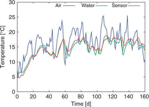
Figure 9. Hydraulic conductivity estimation for real data.
However, in all the previous simulated or real inversions, the initial temperature field in the dike material was supposed to be uniform and equal to the initial temperature of the sensor (7°C in ). This is a very strong assumption that deserves to be checked and that will be studied next.
6. Inversion with non uniform initial temperature distribution
6.1. Description of the simplified test case
In order to see whether both the hydraulic conductivity as well as the initial temperature field can be retrieved from the unique transient response of the sensor, a simulation was generated in a simplified case. It corresponds to solution of the 1D (longitudinal) version of the Darcy and water mass conservation equations (2) and (3), using the 1D reduced equation (9) on the interval [0; Ls], where Ls is the length of the horizontal stream line that goes through the sensor location, see () and x = 0, the corresponding origin, at its intersection with the water in the channel.
The thermal initial and boundary conditions are
(10)
(11)
where T0(x) = ax + b with a = 0.5 K m−1 and b = 1 K.
The boundary heat fluxes correspond to the same type of variation with time as those used in Citation7. They are plotted in .
Figure 10. Variation of the boundary heat flux.
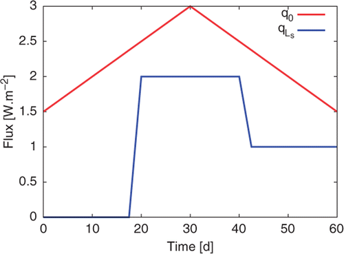
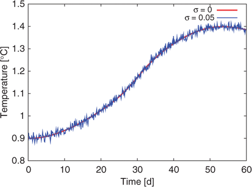
The resulting variation of the sensor temperature is shown in , together with its noised version, using an additive Gaussian independent and identically distributed random variable of zero mean and standard deviation σ equal to 0.5 K. In these simulations, the hydraulic conductivity Kh is equal to 0.0053 m s−1 and the number of time steps is .
Figure 11. Exact and noisy temperature responses at the location of the detector.
6.2. Method for simultaneous estimation of hydraulic conductivity and initial temperature field
In the considered inverse problem, the parameter estimation is linear with respect to the initial temperature field and non-linear with respect to Kh. So, this field can be put under a parameterized column vector form T0, where , where
is the value of hydraulic conductivity that has been used in the model and j the index of the space discretization to the initial temperature distribution:
.
Because of linearity, it is possible to get an estimate of T0 for each value
of the hydraulic conductivity by a regularized minimization of the following criterion:
(12)
where
is the sensitivity matrix of response Ts in a column vector form corresponding to the times of observation, to initial temperature T0 for a given conductivity
and
and
are the corresponding sensitivities matrices to the q0 and
fluxes (parameterized over a local time basis):
with
. Without regularization, minimization of (11) is explicit:
Even if it is possible to use a regularized version of (11), we have chosen to use the an adjoint method coupled with the Tikhonov regularization here. Of course, the heat flux column vectors q0 and
are supposed to be known here.
6.3. Adjoint method
6.3.1. Adjoint equation
The adjoint equation is
(13)
where θ is the adjoint state variable. The boundary and initial conditions become
(14)
6.3.2. Tikhonov regularization
We use a second-order Tikhonov regularization for the space points, except at the borders where a constraint is set to keep an initial temperature close the to the neighbouring fluid
(15)
with β1 = 10−8 and β2 = 10−1.
6.3.3. Algorithm and gradient calculation
To solve the inverse problem, we use an LBFGS algorithm, which implies that we need to calculate the cost function and its gradient. So, the solution of the model (9) is calculated first for t ∈ [0, tf] to get . Solution of the adjoint model (12) is calculated next with the previous results for t ∈ [0, tf]. Finally, the cost function given by (14) with T0 = θ(x, t = 0) and the gradient of the criterion, with
.
6.3.4. Inversion from exact responses
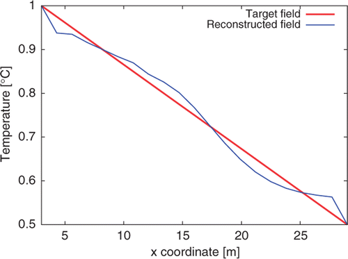
Variation of the criterion 𝒥′, for different values of is shown in . The minimum
is very clear: it is very close to the exact value
. One also sees that the estimation of initial temperature profile becomes difficult for large values of the hydraulic conductivity: this can be explained by the fact that higher velocity values make the remembrance of the initial thermal field last for short times for high Péclet numbers with dominant advection. The corresponding estimated initial temperature distribution is shown .
Figure 12. Variation of the minimized criterion for different values of the hydraulic conductivity.
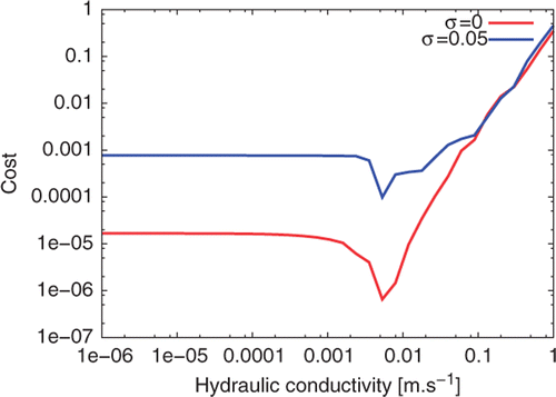
Figure 13. Exact and optimal estimated initial temperature distribution – exact response.
6.3.5. Inversion from noisy responses
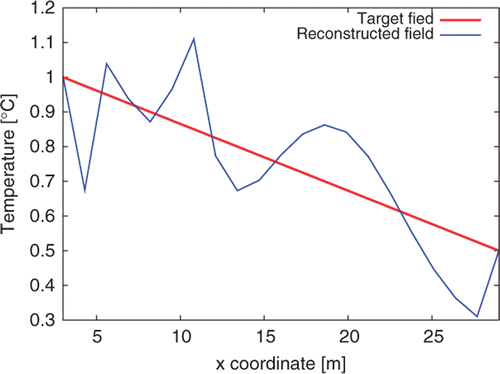
The same approach can be made for a noisy response: it corresponds to a replacement, in equalities (11) and (14), of exact column temperature vector Tsensor by its noisy version Tnoisy shown in .
The minimum remains practically unchanged with respect to the exact response case, (). The exact and reconstructed temperature distributions are plotted in : the reconstruction is naturally not as good as in the preceding case.
Figure 14. Exact and optimal estimated initial temperature distribution – noised response.
7. Conclusion
We designed three methods for real time leakage's velocity estimation in a soil dike, starting from transient temperature measurements at one single internal point. Observation of data and their inversion using a pertinent reduced model make the estimation of the hydraulic conductivity possible. This parameter is the dominant one in the model that governs water leakage. The three methods, that use estimation algorithms based on Kalman's filter, yield unbiased estimations, but the last one (with the one dimension model) performs better in terms of robustness, computing time and precision.
The effect of the unknown initial temperature field has been studied: its simultaneous estimation together with the hydraulic conductivity has been shown to be possible, thanks to an adjoint constrained regularization technique for high enough flow rate in a simplified test case.
If an application field of this method is now considered, estimation of a single parameter starting from recorded values of three temperatures (soil, air and water) is probably not robust enough, since many other parameters or assumptions of our state model are not precisely known (porosity, thermal dispersion coefficients, non-homogeneous character of the dike material, etc.). So two different approaches deserve to be considered, in order to get more robustness to the leakage flow rate estimation. One approach would consist in adding a third parameter (together with Kh and T0) in the estimation, such as a parameter present in the definition of Λxx or in studying the bias on Kh caused by departure of this third parameter from its nominal (non-estimated) value. An alternative approach would be to use an experimental identification of the transfer function of the system, the air temperature being the input and the water and the soil temperatures being the two outputs: this approach would not only be pertinent for leakage detection but can also provide interesting informations if it is associated to the state approach presently used.
References
- Moyne, C, Didierjean, S, Amaral Souto, HP, and Da Silveira, OT, 2000. Thermal dispersion in porous media: One-equation model, Int. J. Heat Mass Transfer 43 (2000), pp. 3853–3867.
- Diersch, JJG, 2005. FEFLOW 53 Reference Manual. Berlin: Wasy GmbH; 2005.
- Gerkens, C, Ullrich, C, Mateus, M, and Heyenan, G, , Comparaison de techniques de validation dynamique de données, SISMO, 2006 http://www.lassc.ulg.ac.be/bibli/gerkens-2006-1.pdf.
- Kaipio, J, and Somersalo, E, 2007. Statistical inverse problems: Discretization, model reduction and inverse crimes, J. Comput. Appl. Math. 198 (2) (2007), pp. 493–504.
- Pham, DT, Verron, J, and Roubaud, MC, 1998. A singular evolutive extended Kalman filter for data assimilation in oceanography, J. Mar. Systems 16 (1998), pp. 323–340.
- Moireau, P, Chapelle, D, and Le Tallec, P, 2008. Joint state an estimation parameter for distributed mechanical systems, Comput. Methods Appl. Mech. Eng. 197 (2008), pp. 659–677.
- Bourquin, F, and Nassiopoulos, A, 2011. Inverse reconstruction of initial and boundary conditions of a heat transfer problem with accurate final state, Int. J. Heat Mass Transfer 54 (2011), pp. 3749–3760.