Abstract
This article presents a multi-objective optimization (MO) formulation to detect cracks in structures using time-domain acceleration responses combined with power flow balance conditions. No additional sensors are required to ensure power flow balance. This is an application of inverse problem formulation whereby the unknown structural stiffnesses are estimated by minimizing the difference between the measured and theoretically predicted accelerations; simultaneously ensuring the net power flow balance in the substructure is zero. Numerical simulations are performed for identifying a lumped mass system and damage detection in a cantilever beam of 20 elements with single crack. Effects of noise are also taken into account by contaminating the measured responses with up to 5% Gaussian noise. The particle swarm approach is used as the optimization algorithm, and the objective function is defined to minimize the error with weighted contribution of both acceleration and power flow parameters. The effects of various weighting factors are studied. It is shown that significant improvement in accuracy of damage detection is achieved by the combined method, when compared to previous methods. The enhanced accuracy of identification could imply the use of fewer sensors for this method.
1. Introduction
System identification (SI) is a process of constructing the mathematical model of a system based on input and output observations. SI can be applied to structural health monitoring and damage assessment by determining a particular set of value that changes the structural physical properties and comparing them with previously determined values or original values. SI from measured input/output data has gained great importance because of the availability of powerful identification algorithms. It is proposed here that the study of power flow balance in substructures and using it as an additional criterion in the objective function could improve the uniqueness of the results. This is validated using numerical examples.
Modal analysis techniques were developed for damage detection because of the observation that structural properties have consequential behaviour on the natural frequency, mode shapes and frequency response function. Modal analysis techniques have been popular in detecting and locating damages in structures. A two-stage identification algorithm using the changes in natural frequencies and static displacements for identifying the structural damages is presented in Citation1. Natural frequency changes alone may not be sufficient for unique identification of the structural damage, as same crack length at different locations may cause the same amount of frequency change. The position of cracks and their magnitudes were detected observing the changes in natural frequencies Citation2. Structural damage was detected using multi-objective optimization (MO), keeping variations in natural frequency and mode shapes as individual objective functions Citation3.
Alterations were made on a finite element model in its undamaged state to reflect the changes in behaviour because of occurrence of damage using time-domain approach for detecting damages Citation4. In Citation5, the presence of damage in structures was located by evaluating the changes in flexibility matrix of the structure, using modes of vibration. To obtain modal parameters full modal analysis is required, which is time consuming for large structures. Crack position and magnitude can be identified in structures by examining the local flexibility introduced by cracks. A cracked finite model for Timoshenko beam with shape functions for the transverse and rotational displacements based on Hamilton's principle with crack section represented as an elastic hinge was presented in Citation6. The effect of cracks on the stiffness matrix and consistent mass matrix was investigated and a procedure was proposed for identifying cracks in structures using modal analysis Citation7. Damage detection in a plate substructure was performed using an orthotropic crack finite element model, based on the strain energy equivalence principle using responses in the time domain Citation8.
In Citation9, the method of receptances was presented to predict the vibrations of a combined system from the subsystem receptances, which is used for power flow calculations in a frequency domain approach. The receptance method can be used for evaluating junction forces and displacements. Power flow calculations were made between two independently and randomly excited harmonic oscillators Citation10. In the aforementioned study, the steady-state partition of energy between two subsystems were calculated using a power flow model, and the parameters which govern the partition were studied. The concept of power flows was also used to determine the time-averaged energy levels of each member fitted with tuned vibration absorbers Citation11. In the aforementioned study, power flows are calculated using the time-averaged product of force and velocity at the input and coupling points of a general structure made of axially vibrating rods. Power flows for an intermediate rod system was calculated based on dynamic substructure approach by combining force balance equations with geometrical compatibility equations Citation12.
Non-classical optimization algorithms such as genetic algorithms (GAs) are usually used to identify the unknown structural parameters with substructural and progressive identification methods in time domain Citation13. As opposed to classical algorithms such as calculus-based methods, non-traditional algorithms are numerically robust and do not get trapped in a local minima Citation13. An ideal substructure method is one which identifies the parameters of the substructure without the necessity of measuring responses outside the substructure. This article uses such a substructure approach to identify crack damages based on time-domain acceleration responses.
In this study, MO of combined power flow balance and conventional acceleration matching has been used for detection of damage in structures. The objective function is made up of a weighted combination of power flow balance and acceleration matching components. From the literature survey, it appears that combined power flow balance and acceleration matching concept with weighting factors has not yet been applied for structural SI. This article presents and discusses the possibility of adding a power flow matching criteria to improve the uniqueness of the solution.
2. Time-domain substructure method
Modelling of complex engineering structures in detail normally requires a large number of degrees of freedom (DOFs). For detection of damage in structures with large number of DOFs, it is frequently not practical to carry out complete structural identification of the global structure because of numerical difficulty in convergence and accuracy of estimation. It is therefore better to divide the structure into smaller substructures, with smaller DOFs, thus requiring fewer sensor measurements. In the formulation shown below, it is not required to know the responses outside the substructure of interest. The equation of motion for a complete structure can be written as
(1)
where M, C and K are the mass, damping and stiffness matrices, respectively, x is the displacement vector, the over dot denotes differentiation with respect to time t and P(t) is the excitation force vector. The equation of motion for complete structural system can be written as explained by the method described in Citation13,Citation14.
(2)
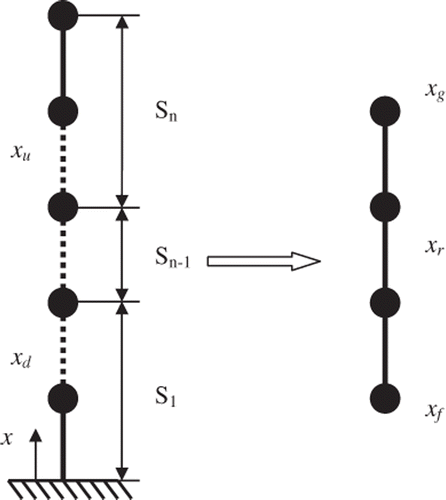
where the subscript r denotes internal DOFs of the concerned substructure, subscripts f and g denote the interface DOFs and u and d denote the DOFs of the remaining structure on either side, as shown in . In , S1 and Sn represents first and last substructure, respectively.
Damping plays an important role in dynamic structural analysis, among the various damping models, the modal damping and Rayleigh damping models are most popular and frequently used for SI Citation15. The current formulation uses Rayleigh damping to model the structural damping. In Rayleigh damping, a damping matrix is represented by a linear combination of the mass and stiffness matrix.
(3)
where α and β are the Rayleigh damping coefficients obtained from the information of two modes. The equations of motion are expressed as a system of partitioned equations Citation13,
(4)
For the substructure considered, the equations of motion can be extracted from Equation (4) to yield
(5)
where subscript j denotes combined DOFs f and g at the interface. Equation (5) can be rearranged to bring the interior partitions to the left and interface effects in the form of a force on to the right as,
(6)
where Pr(t) is the force applied on the interior node(s). If there is no excitation within the substructure, Pr(t) is set to zero. The right side of Equation (6) is treated as input to the substructure, and without the Pr(t) term, it represents forces induced by motion at the interface DOFs – these may be referred to as interface motion forces. To compute the interface motion forces (coupling forces), the substructure interface displacements, velocities and accelerations are required. These interface accelerations
have to be obtained experimentally, and thereafter integrated to obtain the velocities
and displacements xj. A few experimentally measured acceleration responses
at N points inside the substructure are also required. The estimated accelerations
at N points are obtained from the mathematical model from the left-hand side of Equation (6). For correct identification,
has to match the experimentally measured response
. In this study, experiments are numerically simulated from responses generated from a fully defined model of the structure and these are polluted with Gaussian noise with zero mean and 3–5% standard deviation to simulate experimental errors. Using the particle swarm optimization (PSO) algorithm, the following fitness (objective) function is minimized, which is the sum of the square of deviations between the measured and estimated accelerations.
(7)
The superscripts m and e denote measured and estimated responses for fitness evaluation. L is the number of time steps, and N is the number of measurement sensors used. Ideally, it must be minimized to zero, but usually it approaches a value close to zero.
3. Time-domain power flow calculations
The concept of time-averaged power flow is illustrated in , which shows the power flow between substructure-1, substructure-2 and substructure-3 when substructure-2 is excited by a force, F(t).
The applied excitation introduces input power (Pin) into the substructure-2, which depends on the time-averaged product of force and velocity at the forcing point of the substructure-2. The output power (Pout) components of substructure-2 are power dissipated (Pdiss) due to damping effects in that substructure-2 and power transmitted (Ptran), which is transmitted across the interface to the adjacent substructures one and three. When all the beam substructures are excited, it is possible for net power transmission to be positive or negative across a substructure interface, depending on which substructure is subjected to stronger excitation, mode shapes and other vibrational factors. The time-averaged power flows are calculated using the product of force and velocity at the input and substructure boundaries of a structure. The time-averaged power at any point in terms of force, F(t) and velocity, V(t) over a period, T is given by
(8)
The steady-state time-averaged power balance equation of beam substructure is given by
(9)
(10)
The power input to the substructure can be represented as
(11)
where Pr(t) is the force acting on the substructure node(s), and
is the respective nodal velocity at those locations. The substructure interior velocity
is not explicitly measured at any sensor and it is iteratively calculated by the optimization algorithm. At the correct value of stiffness and damping coefficients, the correct values of
are recovered.
Power transmitted across the substructure interface can be represented as
(12)
The term inside the square bracket represents interface motion forces (coupling force) acting at the substructure interface and is evaluated as explained in Equation (6). The interface accelerations has to be obtained experimentally, and thereafter integrated to obtain the velocities
and displacements xj to evaluate power transmitted.
The power dissipated in the substructure due to damping is given by
(13)
The term inside the square bracket represents damping force acting at beam substructure interior and the interior velocities are obtained as explained in Equation (11) to calculate the power damped inside the substructure.
(14)
where Pb is the steady-state time-averaged power balance of the substructure obtained by using Equations (11–13) with respective velocities obtained iteratively. It may be noted that no additional sensors are needed for evaluating power flow balance. Thus, the second objective function is,
(15)
Thus f2 has to be minimized to zero to satisfy power flow balance. Equations (7) and (15) are the two objective functions to be simultaneously minimized.
4. Weighted aggregation approach
An MO problem is a problem where two or more objectives need to be minimized simultaneously. The difficulty with MO problem is that no single optimal solution exists. Instead, an optimal solution exists for each separate objective in the solution space. One of the basic methods of MO is to assign different weights to the objective functions and then adding them together into a single function, which we refer to as weighted scheme. In the proposed method, the two objectives which have to be minimized are acceleration matching and ensuring power flow balance. The weighted objectives are added up as
(16)
where i = 1, … , q are the number of objective functions and wi are non-negative weights. The combined MO function can be represented as
(17)
Weighting factors w1 and w2 take values between zero and one, such that Σw = 1 and can be either fixed or dynamically adapting during the optimization. In the proposed method, weights for acceleration matching and power flow balance matching are fixed, and the search is repeated to minimize the normalized objective functions fNorm 1 and fNorm 2. Normalized objective functions are obtained by individually minimizing and maximizing the ith objective function within the same feasible region as explained in Citation16.
5. Representation of crack damage in the substructure
Cracks occurring in structures lead to local changes in the stiffness of structural elements and change the static and dynamic characteristics. Cracked structures have been modelled using different methods by various investigators. The stiffness matrix and inertia matrix corresponding to the transverse and rotational motions with elements appearing as functions of flexibility coefficient at crack locations were presented in Citation17. However, the inertia matrix does not affect natural frequencies of the beams analysed, hence inertia matrix in the same form for a non-cracked structure can be applied for identification. Similarly, stiffness and consistent mass matrices for a two node cracked Timoshenko beam element for detecting cracks were developed in Citation7.
The proposed method presented here uses a stiffness matrix for cracked finite element following the methods described in Citation7,Citation17. The stiffness matrix for a cracked element with middle crack shown in can be written as
(18)
where E denotes Young's modulus, I the geometrical moment of inertia of the beam cross-section, L the length of the beam element, B the width of the element, H the height of the element, a the depth of crack in the element and K is the flexibility coefficient at the crack location.
From the above element stiffness matrix it can be seen that when K = 0, the form of stiffness matrix is the same as for the non-cracked element. The flexibility coefficient at the crack location can be expressed as given in Citation17
(19)
Flexibility, c at the cracked cross-section of the beam under consideration can be expressed as given in Citation17
(20)
where A is the crack area, σ the applied nominal stress, σY the material yield strength and F the correction function.
Correction function, F can again be expressed as given in Citation16
(21)
The flexibility coefficient at the crack location can be also expressed as given in Citation7.
(22)
where f(ζ) is a correction function which takes into account the body and crack geometry and depends on the dimensionless crack ratio ζ = a/H, which can be expressed as given in Citation7.
(23)
(24)
The flexibility coefficient at the cracked location can be evaluated by using Equations (19–21) or from Equations (22–24). In the proposed crack detection model equations, Equations (22–24) are used to evaluate the flexibility coefficient at the crack location, because of its better accuracy compared to Equations (19–21), which require two integrations.
6. Particle swarm optimization
The proposed identification method uses the PSO technique for minimizing the objective functions. PSO is a population-based continuous optimization technique based on the simulation of the social behaviour of birds, bees or a school of fishes (behaviourally inspired). The system is initialized with a population of random solutions and iterated a fixed number of times or until a minimum error based on desired performance index is reached. In PSO, the potential solutions, called particles, move through the problem space by following the current optimum particles. The basic PSO algorithm consists of the velocity and position equation as given below:
(25)
(26)
where i is the particle index, k the discrete time index, v the velocity of the ith particle, x the position of the ith particle/present solution, pi the historically best position/solution found by the ith particle, G the historically best position/solution found among all the particles and γ1,2 the random numbers in the interval (0, 1) applied to the ith particle.
An inertia term ϕ and acceleration constants α1,2 are also included. The inertia function is commonly taken as either as a constant or as a linearly decreasing function from 0.9 to 0.4. The acceleration constants are set equal to two.
The most important difference between PSO and other evolutionary algorithms is that PSO chooses the path of cooperation over competition. Also, PSO explicitly keeps track of the historically best values. PSO does not have genetic operators such as crossover between individuals and mutation and other individuals never substitute particles during the run. There are some indications from previous studies of the superiority of PSO over GA. PSO and GA techniques were compared and observed for optimization applications, the performance of PSO was better than that of GA Citation8,Citation18 with superior convergence and accuracy. Hence, PSO is used in this study.
7. Numerical examples
In order to demonstrate the proposed substructure identification with combined power flow balancing and acceleration matching, the concept is applied to a lumped mass substructure model studied in Citation13 under harmonic excitation and finally a cracked cantilever beam model taken from Citation7 for crack identification.
Experimental measurements are numerically simulated from the responses generated from a fully defined model of the structure. Later, the actual structural parameters such as stiffness are considered unknown in the same model, and these are estimated using the inverse formulation with multi-objective approach. The PSO parameters are set as 50 particles (swarm size), iterations of 200 for lumped mass example and 500 for beam example, a linearly decreasing inertia function from 0.9 to 0.4, and acceleration constant is set to two. All numerical simulations are performed in MATLAB in the hardware platform of 4 GB RAM and dualcore processor of 2.0 GHz.
The performance of the proposed method of identification is evaluated by (1) comparing the accuracy of identification obtained with a single objective (only acceleration matching represented by A1) and multi-objective (acceleration and power flow matching represented by AP) for each model and (2) comparing the accuracy of identification with that of the original papers Citation7,Citation13. The effect of variation in weighting factors for MO of acceleration and power flow balance matching is also studied.
7.1. Substructure identification of lumped mass system
The substructure identification of a lumped mass model studied in Citation13 is used here. Rayleigh damping model with damping coefficients α and β providing approximately 3% damping ratio for the first two modes of vibration is used. Natural frequencies for first two modes of vibration are 1.004 Hz and 2.516 Hz, respectively. The actual structural parameters are listed in .
Table 1. Actual structural parameters for 10 DOFs lumped mass system.
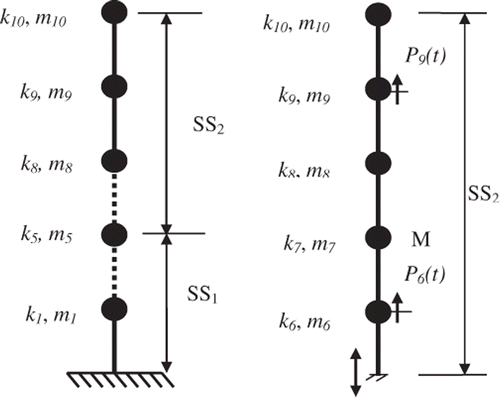
As shown in , the mass of the structure is lumped at each floor level with mass m1–m10 and springs of stiffness k1–k10. The second substructure (SS2) starts from levels 5–10 and response at level 5 is input (interface acceleration) in the substructure formulation. An acceleration sensor (M) is assumed to be placed to obtain response measurement at the seventh level in SS2 for defining the fitness function. The interface response measurement at fifth level is also necessary for evaluating the interface forces in the substructure formulation.
In the identification procedure, stiffness parameters (k6–k10) are assumed as unknown resulting in five unknown parameters for substructure SS2. The structure is assumed to be excited at third, sixth and ninth levels with sinusoidal forces 20 sin(2π10t), 20 sin(2π30t) and 20 sin(2π60t), respectively. The responses from 10 to 15 s are considered with 0.002 s time interval.
To analyse the effect of weighting factor variation in MO, three different test cases were analysed for the search. The first case considers weights of {0.75, 0.25}, where first weight represents acceleration matching (75%) and second weight represents power flow balance matching (25%), respectively. The second case considers weights of {0.5, 0.5} and last case considers weights of {0.25, 0.75}, respectively. Responses and excitations with and without noise contamination are considered, i.e., 5% Gaussian noise is considered to test the robustness of the proposed method by polluting the accelerometer responses. The PSO search is carried out in a range of ± 50% of the actual structural stiffness values.
The identified results from only acceleration matching () is compared with the results obtained from combined acceleration and power flow balance matching (). also compares the effect of weighting factor variation in the objective function. Comparing the errors in with , it is evident that MO with weighted aggregation technique is a more accurate method of identification than only acceleration matching.
Table 2. Identified structural parameters for only acceleration matching.
Table 3. Identified structural parameters for acceleration and power flow matching.
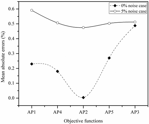
The mean absolute errors for SS2 are 2.06% and 2.87%, respectively, for only acceleration matching case with noise-free and 5% noise pollution cases. For the same cases, the respective errors for MO with weight factors {0.5, 0.5} are 0.004% and 0.475%. Thus, there is a significant reduction in mean absolute error of 99.80% and 83.45% compared with only acceleration matching. From , it is seen that weight factors {0.5, 0.5} give better results than {0.25, 0.75} and {0.75, 0.25} for both noise-free and noisy cases.
explains graphically the accuracy of using various combinations of weighting factors. Weighting factors on the x-axis are {0.75, 0.25}AP1, {0.6, 0.4}AP4, {0.5, 0.5}AP2, {0.4, 0.6}AP4 and {0.25, 0.75}AP3, respectively, and shown with mean absolute errors on the y-axis. It appears that weight factor corresponding to {0.5, 0.5} gives the least error. Henceforth, only {0.5, 0.5} weighting factors are used in further examples.
The result is now compared with those from the original paper Citation13 from which this numerical example is taken. There, the average mean absolute error of 4.0% was noted with only acceleration matching using GA. In this study (using PSO), the mean absolute error with only acceleration matching for SS2 is 2.87%, and with combined acceleration and power flow balance matching (AP2), the respective error reduces to 0.475% for the noisy case.
7.2. Identification of single crack damage magnitude
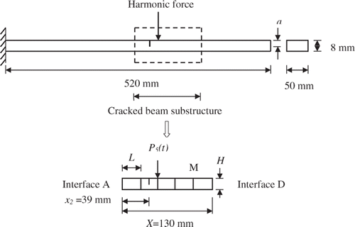
Crack damage identification is carried out first to determine the crack depth (i.e. magnitude) of a beam substructure with a single crack. The cracked steel cantilever beam studied in Citation7 is 520 mm long, 50 mm wide and 8 mm thickness as shown in with Young's modulus (E) 2.06 × 10¹¹ N m−2, and the mass density (ρ) is 7.85 × 10³ kg m−3. The cantilever beam is modelled with 20 Euler beam elements and divided into four substructures. The second substructure from the right end of the beam with a single crack is considered for detecting crack using the proposed method. The substructure under consideration consists of five elements, with crack located at the middle of the second element from the left end of the beam substructure as shown in . Each finite element has two nodes (each with transverse and rotational DOFs). The depth of the crack varies from 0.05H to 0.1H from case to case.
shows the detailed comparison of a few natural frequencies of the undamaged and damaged beam for different crack depths with crack location (x2) at 39 mm from the left end of the beam substructure. The excitation frequency (50 Hz) is above the first natural frequency of 24.48 Hz. Rayleigh damping model with damping coefficients α and β providing approximately 3% damping ratio for the first two modes of vibration is used. The synthetic data of the numerical model are first calculated in terms of displacement, velocity and acceleration using Newmark's method with constant time step of 0.001 s from 3 to 5 s using the point harmonic excitation force (P5(t)), 1.5 sin(2π50t) in vertical direction. The numerically calculated accelerations are polluted by artificially adding Gaussian white noise with zero mean and standard deviation of 3% and 5% to simulate experimental errors.
Table 4. Natural frequencies of the beam for different cases of damage depths.
The experimentally measured acceleration response at point M in is required for fitness evaluation. Accelerations at all interface nodes are also required for evaluating interface forces. Experimental values are numerically simulated using a fully defined mathematical model by providing cracks at all elements inside the beam substructure. The estimated or predicted acceleration at point M is obtained from the mathematical model that is from the left-hand side of Equation (6) for fitness evaluation.
In the first case, only magnitude of crack location (element) is treated as unknown. As the beam substructure contains five elements, the total unknowns are the five crack depths. The optimization variables to be identified are the normalized values of ζ(a/H) for each element in the beam substructure with two different cases of crack depths. The lower bound and upper bound for PSO optimization to identify cracks are set as 0 and twice the normalized crack depth (ζ). The cracked element is indicated in , and the exact normalized depths are 0.05 and 0.1 (i.e. for 0.05H case and 0.1H case).
In the proposed method of crack identification, weights for acceleration matching and power flow balance matching are fixed as {0.5, 0.5}. shows the average absolute error corresponding to crack depth a = 0.05H and 0.1H cases is 3.1%, which is less than 5.25%, the average absolute error corresponding to acceleration only matching for noise-free case. For 5% noise polluted case, the average absolute error corresponding to weight factors {0.5, 0.5} is 6%, which is again significantly less than the average absolute errors corresponding acceleration only matching.
Table 5. Identified values of beam substructure normalized damage magnitude.
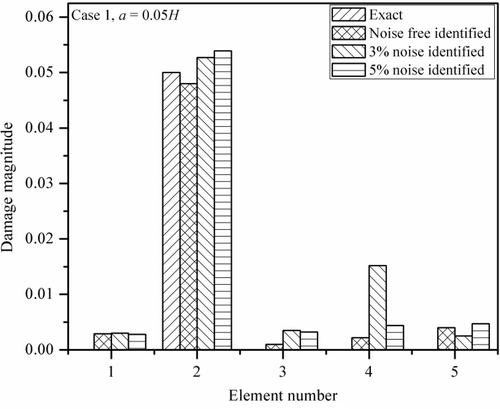
Normalized damage magnitude of a single crack for various cases of noise pollution (0%, 3% and 5%) with crack depth, a = 0.05H is shown in . From the plot, it is clear that the cracked element is the second element and the exact damage magnitude is 0.05.
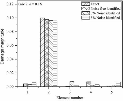
shows the normalized damage magnitudes with a single crack for various cases of noise pollution (0%, 3% and 5%) with crack depth, a = 0.1H. The plot clearly shows that for a = 0.1H, the cracked element is the second element, but for other elements also it shows some non-zero values of damage magnitudes. These are very small in comparison with the second element, which is the original cracked element. The deviation from exact value increases as the noise pollution increases and is more when the depth of the crack is small. The results show that the proposed method of combined acceleration matching and power flow balance can be effectively used for the identification of damage magnitudes irrespective of crack depths.
7.3. Identification of single crack damage magnitude and location
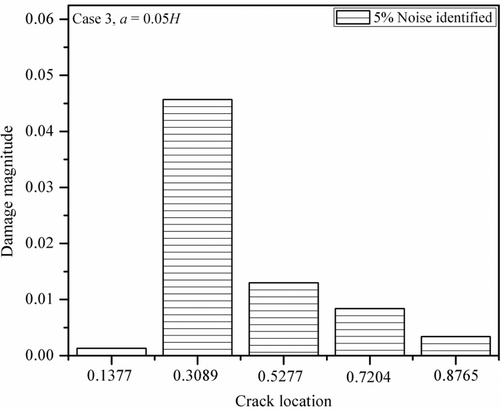
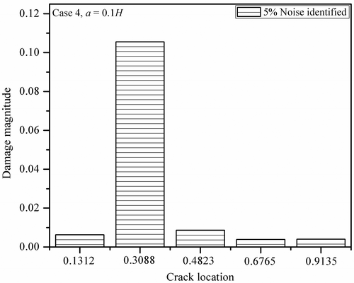
In this case, the damage detection by the proposed method of combined power flow balancing and acceleration matching is applied to determine the damage magnitude and location simultaneously for a single crack. The location of crack is treated as unknown along with its magnitude and as there are five elements inside the beam substructure, there are in total 10 unknowns (i.e. magnitude and location). Each element in the beam substructure needs to be identified for the normalized value of magnitude ζ(a/H) and the normalized value of location γ(x/X) for three different cases of crack depths. The lower bound and upper bound for PSO optimization to identify crack magnitude are set as zero and twice the normalized crack depth (ζ). Lower bound and upper bound to identify normalized crack location are set as zero and L respectively. The cracked element is indicated in , and the actual normalized crack magnitude values are 0.05, 0.1 and 0.5 for 0.05H, 0.1H and 0.5H crack depths, respectively. The actual normalized value (γ) of location of crack in all the case is 0.3.
The normalized location values (γ) are evaluated by identifying the respective length of each element, then taking half the length of the identified element length (crack is at the middle of the element). Add half the identified element lengths of each element (L/2) to the exact length towards the left end of the substructure from that element and finally divide by the length of the beam substructure (X). For example in , for the second element, the normalized location magnitude is given by γ = x2/X, where x2 = L + L/2. The effects of noise in the signals are also considered in this example.
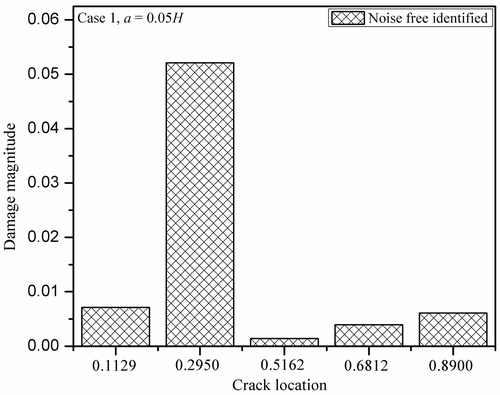
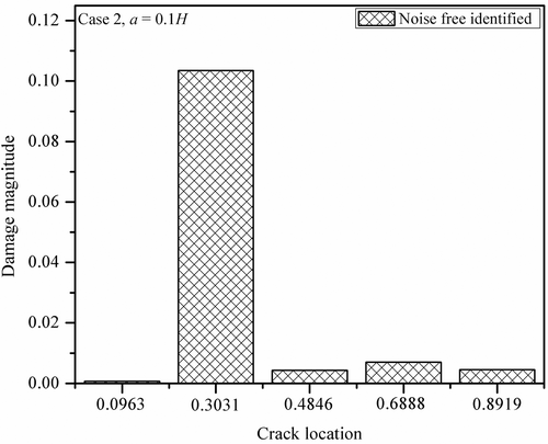
shows the identified values of beam substructure normalized damage magnitudes, when normalized location of the crack is also identified. Comparing and, both absolute average error and absolute maximum error increase when the location of the crack is also identified as the number of unknowns increased from five to ten, and the convergence is more difficult.
Table 6. Identified values of normalized damage magnitude and location.
shows the variation of identified magnitude and location for the unpolluted case for crack depth a = 0.05H. The crack magnitude error is 4.2% and crack location error is −1.67%, and for non-cracked elements also the errors are more, but still the cracked element can be identified.
shows the variation of identified magnitude and location for unpolluted case for crack depth a = 0.1H. When the crack depth is 10% of the beam thickness (a = 0.1H) without noise pollution, the crack magnitude error is 3.50% and crack location error is 1.03%. When the depth of crack increases, it is easier to detect the crack accurately.
shows that for 5% polluted case, the magnitude errors are more when the crack depth is small in comparison with the other cases of crack depths. For a = 0.05H case with 5% noise pollution, the magnitude error is −8.6% and location error is 2.97%.
In , the error associated with crack magnitude is again greater in comparison with crack location error when noise pollution increased to 5%. The magnitude error is 5.62% and location error is 2.93%, and for non-cracked elements, the errors are less because of the increased depth of the crack, but still the cracked element can be identified. The reason for more error associated with crack magnitude might be the large search space for damage magnitude in comparison with the location magnitude.
Now, the experimental result from the original paper Citation7 is compared with the results obtained from the proposed method. The actual values for normalized crack depth (ζ) and normalized crack location (γ) given in Citation7 are 0.500, 0.760 and the identified values are 0.487 and 0.756, respectively. In this study, the actual values are ζ = 0.500 and γ = 0.3, the identified values are 0.5046 and 0.3015, respectively, for unpolluted case. For 5% polluted case, the respective values are 0.4914 and 0.3085. The observed errors in Citation7 associated with identified ζ and γ are 2.6% and 0.53%. In this study, the identified ζ and γ errors are 1.72% and 2.8%, respectively, for 5% noise polluted case. For unpolluted case, the respective errors are 0.92% and 0.5%.
The results show that for contaminated and uncontaminated noise cases, the proposed damage detection method is effective and can be used with substructures. As expected for all the studied cases, the largest errors are observed when the crack size is small combined with high noise contamination.
8. Conclusions
In this article, a time-domain-based method for detecting crack magnitude and location using a combination of acceleration matching and power flow balance matching is presented, with a weighted multi-objective (MO) function. The magnitude and location of crack were correctly identified using the MO structural identification approach for two numerical examples. This combined approach identifies crack location and depth with better accuracy than the conventional acceleration matching methods and also the methods used in the original papers from which they were referred. The enhanced accuracy of identification could imply the use of fewer sensors for this method. The result also shows that objective function with equal weight factors {0.5, 0.5} for acceleration matching and power flow balance gives best results. The concept is illustrated using a simple lumped mass system and also a cracked Euler–Bernoulli beam. This can be readily extended to more complex structures such as trusses and frames.
References
- Wang, X, Hu Fukunaga, N, and Yao, ZH, 2001. Structural damage identification using static test data and changes in frequencies, Eng. Struct. 23 (2001), pp. 610–621.
- Ostachowicz, WM, and Krawczuk, M, 1991. Analysis of the effect of cracks on the natural frequencies of a cantilever beam, J. Sound Vib. 150 (2) (1991), pp. 191–201.
- Liu, H, Xin, K, and Quanquan, QI, 2011. Study of structural damage detection with multi-objective function genetic algorithm, Procedia Eng. 12 (2011), pp. 80–86.
- Majumder, L, and Manohar, CS, 2003. A time domain approach for damage detection in beam structures using vibration data with a moving oscillator as an excitation source, J. Sound Vib. 268 (2003), pp. 699–716.
- Pandey, AK, and Biswas, M, 1994. Damage detection in structures using changes in flexibility, J. Sound Vib. 169 (1) (1994), pp. 3–17.
- Viola, E, Nobile, L, and Federici, L, 2002. Formulation of cracked beam element for structural analysis, J. Eng. Mech. 128 (2) (2002), pp. 220–230.
- Viola, E, Federici, L, and Nobile, L, 2001. Detection of crack location using cracked beam element method for structural analysis, Theor. Appl. Fract. Mech. 36 (2001), pp. 23–35.
- Sandesh, S, and Shankar, K, 2010. Application of a hybrid of particle swarm and genetic algorithm for structural damage detection., Inverse Probl. Sci. Eng. 18 (7) (2010), pp. 997–1021.
- Bishop, RED, and Johnson, DC, 1960. The Mechanics of Vibration. Cambridge: Cambridge University Press; 1960.
- Lyon, RH, and Maidanik, G, 1962. Power flow between two linearly coupled oscillators, J. Acoust. Soc. Am. 34 (5) (1962), pp. 623–639.
- George, SK, and Shankar, K, 2006. Vibrational energies of members in structural networks fitted with tuned vibration absorbers, Int. J. Struct. Stab. Dyn. 9 (2006), pp. 269–284.
- Wang, ZH, Xing, JT, and Price, G, 2002. Power flow analysis of intermediate rod/beam systems using a substructure method, J. Sound Vib. 249 (1) (2002), pp. 3–22.
- Koh, CG, Hong, B, and Liaw, CY, 2003. Substructural and progressive structural identification methods, Eng. Struct. 25 (2003), pp. 1551–1563.
- Clough, RW, and Penzien, J, 1993. Dynamics of Structures. New York: McGraw Hill; 1993.
- Chen, J, and Li, J, 2004. Simultaneous identification of structural parameters and input time history from output-only measurements, Comput. Mech. 33 (2004), pp. 365–374.
- Deb, K, 2005. Multi-objective Optimization using Evolutionary Algorithms. Singapore: Wiley & Sons; 2005.
- Krawczuk, M, Zak, A, and Ostachowicz, W, 2000. Elastic beam finite element with a transverse elasto-plastic crack, Finite Elem. Anal. Des. 34 (2000), pp. 61–73.
- Panda, S, and Padhy, NP, 2008. Comparison of particle swarm optimization and genetic algorithm for FACTS-based controller design, Appl. Soft Comput. 8 (2008), pp. 1418–1427.
