Abstract
A variety of effective methods have been developed for the numerical reconstruction of scatterers in inverse scattering problems. One type of such methods is based on some indicator functions which show significantly different values inside and outside the scatterers. In this article, we propose a parallel radial bisection algorithm for efficiently imaging the shapes of scatterers based on the indicator methods. We show that the algorithm can essentially reduce the computational complexity of the existing indicator methods, in fact it has optimal computational complexity that does not depend on the space dimensions of the concerned physical problems, namely the complexity is the same for any dimensions. Such space-dimension independence is a significant advantage of the method in three-dimensional applications. The method is easy to implement and overcomes some dominant drawbacks of several existing reconstruction methods for inverse scattering problems.
1. Introduction
This work investigates some efficient numerical methods to reconstruct the shapes of scatterers from the measurement of scattered fields in inverse scattering problems. The shape reconstruction finds wide applications in geophysics, medicine, nondestructive testing and biological studies, and a variety of numerical methods have been developed. Among all the existing methods, one popular and effective type of methods is based on some indicator functions that show significantly different values inside and outside the scatterer. Using such indicators, one can determine if a sampling point lies inside or outside the scatterer, thus estimating its location and geometric shape. Among all the indicator methods, the linear sampling type methods have been widely studied and extended in several directions; we refer to two comprehensive reviews Citation1,Citation2 on the topics. Many variants of the indicator function methods were proposed, such as the probe method Citation3,Citation4, the singular source method Citation5, the gap function method Citation6, the linear sampling method (LSM) [7–10] and the generalized dual space indicator method (GDSIM) Citation11. In this work, we shall present a novel method to speed up the aforementioned indicator methods for more efficiently imaging the shape of the scatterers. For the sake of exposition, we shall consider only the inverse acoustic obstacle scattering by time-harmonic acoustic waves in this work, but our method can be equally applied to other inverse problems, such as the electromagnetic obstacle scattering and inverse medium scattering. Also, we will take two indicator function methods, the LSM and the GDSIM, as examples to describe our new method for the inverse scattering problems.
First we describe the LSM. Consider a bounded obstacle Ω with a smooth boundary embedded in a domain D ⊂ ℝN(N = 2, 3), which may contain multiple separated obstacle components. Given an incident field ui, the presence of the obstacle will give rise to a scattered field us. We take the incident wave to be a time-harmonic plane wave, i.e. ui(x) = eikx·d, where d ∈ 𝕊N−1 is the incident direction, k > 0 is the wave number and . The total field u = ui + us satisfies the following Helmholtz system (cf. Citation7):
(1)
where we write r = |x| for any x ∈ ℝN, and Bu = 0 may be the sound-soft, sound-hard or impedance boundary condition. The scattered field us has the asymptotic behaviour at infinity Citation7:
uniformly for all directions
, where
is the far-field pattern, defined on the unit sphere 𝕊N−1. The inverse scattering problem of our interest is to recover the shape of the obstacle Ω from the measurement of
for
and some fixed k > 0. Now we give a brief description of the LSM for this inverse scattering problem.
Define the far-field operator ℱ: L2(𝕊N−1) ↦ L2(𝕊N−1) as
then consider the far-field equation:
(2)
where
, with
in ℝ2 and
in ℝ3. The LSM is to make use of the blow-up behaviour of the solution g in the integral equation (1.2) as an indicator function to determine the shape of the unknown scatterer. The validity of such method is based on the following theorem.
Theorem 1.1. Citation1, Theorem 4.1]
Assume that k2 is not a Dirichlet eigenvalue for −Δ in when Ω is sound-soft, and is not a Neumann eigenvalue for −Δ in H1(Ω) when Ω is sound-hard. Then the following properties hold:
| 1. | For z ∈ Ω and a fixed ϵ > 0 there exists a | ||||
| 2. | For | ||||
This theorem tells us the important blow-up behaviour of the solution gz to the far-field equation (1.2), leading to the very popular LSM: (1) select a mesh 𝒯h of sampling points in a region D which contains the obstacle Ω; (2) use the Tikhonov regularization and the Morozov discrepancy principle to compute an approximate solution gz for each sampling point z in 𝒯h; (3) determine if a sampling point is inside or outside Ω based on the magnitude of the L2-norm of gz on 𝕊N−1.
Next we describe the GDSIM, which is a variant of the LSM developed in Citation11 for the shallow ocean environment as a parallel waveguide. We write the shallow ocean waveguide as
where h > 0 stands for the depth of the ocean, and the positions at x2 = 0 and x2 = h > 0 represent the ocean surface and bottom, respectively. We consider two positive constants x2,0 and
and their corresponding planes
such that both Γr and Γs are above the obstacle Ω. We assume that the source points and the receivers are located, respectively, on Γs and Γr. Let ui and us be an incident field and its corresponding scattered field, then the total field u = ui + us satisfies the system Citation11
(3)
with some radiative conditions, Bu = 0 may be the sound-soft or sound-hard condition, k > 0 is the wave number. In practice, the point source ui(x) is Green's function for the parallel waveguide without any obstacle Citation8. The direct problem (1.3) has been studied in Citation12,Citation13. The inverse problem of our interest is to determine the scatterer Ω from the measurement of the scattered field us on a line above the unknown object. Let D be a region containing the obstacle Ω, then we consider the integral equation
(4)
It can be shown Citation8 that there is no solution to the integral equation (1.4) for any
, and for any y ∈ Ω, the solution g(xs, y) to (1.4) satisfies
(5)
Based on the above results, we can formulate the so-called GDSIM Citation11: (1) measure the scattered field us along Γr corresponding to each sound source located on Γs; (2) select a sampling region D that contains the unknown obstacle Ω; (3) for each sampling point z ∈ D, solve Equation (1.4) by the Tikhonov regularization; (4) determine if the sampling point is outside the scatterer based on the magnitude of the L2-norm g on Γs.
Both the LSM and the GDSIM are proved to be numerically very robust. However, they are both very expensive computationally: using an n × n or n × n × n mesh, one needs to solve the far-field equation (1.2) or the integral equation (1.4) for n2 times (N = 2) or n3 times (N = 3). In this article, we shall propose some efficient algorithm to significantly speed up these methods. It is known that if less prior information on Ω is available, then larger initial guessing region D should be chosen. Moreover, one should need an extremely fine mesh to achieve a high-resolution reconstruction of the obstacle Ω. When the scatterer consists of more than one component where the distance between two of them is several times larger than the sizes or diameters of these two objects, the initial guess of the region D should be much larger than actually needed to contain all the obstacle components. It is worth noting that the multilevel LSM (MLSM) Citation14 provided an effective technique which is able to reduce the computational complexity of the LSM by one order, namely with a complexity of order O(nN−1). Unfortunately the multilevel LSM fails to deal with scatterers of complex geometry, and some obstacle components may be removed in the reconstruction of the multilevel LSM; see a detailed example in and some discussions about the example in Section 3. Our new method intends not only to avoid the failure of the multilevel LSM but also to require much less computational efforts, in fact it needs only to solve the far-field equation (1.2) or the integral equation (1.4) for 𝒪(log2 n) times, independent of the space dimensions N of the concerned domain, so it improves the computational complexity of the multilevel LSM by one order in three dimensions. In addition, our algorithm is very easy to implement.
In the next section, we will state the motivation and implementation detail of our new method and justify its optimal computational complexity. In Section 3, several numerical examples are presented to demonstrate the robustness and efficiency of the method for both the acoustic obstacle scattering system and the shallow water waveguide model. Note that for the LSM case the data are given around the scatterer, and for the GDSIM case, data are given on a line above the object in a shallow water waveguide. We have considered only the constant refraction index for the water waveguide model in this article, but the method can be equally applied to more practical cases, including the varying refraction index and the ocean over elastic and poroelastic sediments. For more discussions about inverse scattering problems in ocean acoustics, we refer to Citation15.
2. A parallel radial bisection algorithm
In this section, we present a parallel radial bisection algorithm to speed up the indicator type methods. As we will see, the algorithm can reduce the computational complexity of the LSM and the GDSIM significantly. For simplicity, we will describe the algorithm for ℝ2, but all of the results and conclusions can be straightforwardly extended to ℝ3.
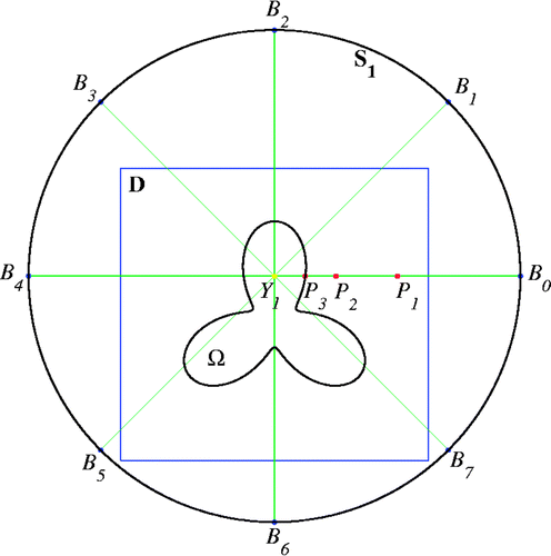
We now describe our parallel radial bisection algorithm for finding a scatterer Ω, which may contain multiple separated components. Let Ω ⊂ ℝ2 or (see Section 1) be an unknown scatterer. We select a region D that contains the scatterer Ω as shown in .
As the first step of our algorithm we need to locate some interior points inside the scatterer Ω, possibly at least one interior point for each separated component in Ω. This process is formulated as the following interior point algorithm.
Interior point algorithm
| 1. | Choose a uniformly distributed coarse mesh 𝒯h of n × n points, Z1, Z2, … , | ||||
| 2. | For i = 1, 2, … , n2, at the grid point Zi: Select m radii For l = 0, 1, … , m, implement the following procedure on the radius Choose the middle point of Select one from m (possibly less than m) interior points randomly. | ||||
| 3. | Return all n2 (possibly less than n2) selected interior points. | ||||
This algorithm is very effective in finding initial interior points, as we will see in our numerical experiments. When the scatterer Ω is not so complicated, a quite coarse mesh, say 5 × 5, is usually sufficient to locate all necessary interior points, one for each separate component of Ω.
Now we are ready to present our parallel radial bisection algorithm.
Parallel radial bisection algorithm
| 1. | Choose a tolerance parameter ϵ > 0 and a cut-off value c; then choose a domain D which contains the scatterer Ω and a radius parameter R. | ||||
| 2. | Run the interior point algorithm with an n × n mesh to generate a set of interior points inside Ω, say Y1, Y2, … , YI. | ||||
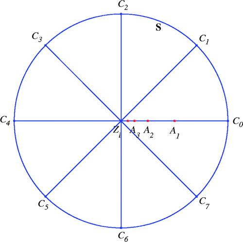
| 3. | For i = 1, 2, … , I, select a circle Si with radius R, centred at the interior point Yi such that the union of all Si enclose D. Then select m uniformly distributed radii on the circle Si; see the radii For j = 0, 2, … , m − 1, do a bisection procedure to locate a boundary point of the scatterer on the radius Choose the middle point of the radius, say, the red point P1 in . Solve Equation (1.2) for gz or Equation (1.4) for g(·, z) and evaluate the norm | ||||
| 4. | Form an approximate boundary of the scatterer Ω using the set of approximate boundary points achieved on each circle Si, i = 1, 2, … , I. | ||||
Remark 2.1
In the first step of the parallel radial bisection algorithm, we can choose the cut-off value c by the strengthened LSM Citation16. And the tolerance ϵ may be chosen differently in each different application, based on the specified accuracy.
Remark 2.2
If one component of the scatterer is not well reconstructed for one interior point, we may choose some other interior points and run the last two steps of the Parallel radial bisection algorithm to improve the reconstruction. The interior point may be easily seen from the reconstructed results in most applications, without running the interior point algorithm again.
Next, we show that the parallel radial bisection algorithm has an optimal computational complexity.
Theorem 2.3
When the parallel radial bisection algorithm is applied to reconstruct a scatterer Ω, the far-field equation (1.2) or integral equation (1.4) is solved 𝒪(log2 n) times in both two and three dimensions.
Proof
When we apply the parallel radial bisection algorithm on the set of selected radii on a specified circle, the total computational cost is the same as the one of longest radius. On this longest radius we do our search for a desired boundary point by bisection, so the far-field Equation (1.2) or integral Equation (1.4) will be solved 𝒪(log2 n) times in total.▪
Remark 2.4
The radial bisection algorithm is also easier to implement than the MSLM Citation14. For implementation of MLSM, one should store the information of those mesh points to be kept for the subsequent reconstruction and determine the grid points to keep or drop at each level, which may take much memory and computational time. The parallel radial bisection algorithm is implemented in parallel on each selected radius, which will save the memory and the computational time essentially, and reduces an n-dimensional reconstruction to a one-dimensional reconstruction.
3. Numerical simulations with discussions
In this section, we present several numerical examples for both inverse acoustic obstacle model and the shallow ocean waveguide model to illustrate the robustness and efficiency of the newly proposed parallel radial bisection algorithm. All the testings are done under the MATLAB environment.
We consider an infinite homogeneous background medium and select the following scatterers:
The synthetic far-field data from the direct problem are generated by solving the combined-layer potential operator equation with the Nyström method Citation7, which converges exponentially for analytic boundaries. We compute the far-field patterns at 64 equidistantly distributed observation points (cos tj, sin tj), tj = 2jπ/64, j = 0, 1, … , 63, corresponding to 64 equidistantly distributed incident directions (cos τj, sin τj), τj = 2j/64, j = 0, 1, … , 63, around the unit circle. In the numerical experiments, we add the random noise to the far-field data in the following form:
where r1 and r2 are two uniform random numbers, both ranging from −1 to 1, δ is the noise level, which is always taken to be 3% unless otherwise specified. At each sampling point z on a selected radius, the corresponding far-field equation (1.2) is solved by the Tikhonov regularization method in combination with the Morozov discrepancy principle, and the regularization parameter equals 10−6. The wave number k is taken to be 3, and the tolerance ϵ is chosen to be 10−5.
We will take the sampling region D to be [−5, 15] × [−5, 15] in the first two numerical simulations, and the mesh size of the coarse mesh is chosen to be 5, so we have a total of 25 grid points on the coarse mesh. We always choose 10 radii corresponding to the each coarse mesh point for finding the interior points, and all the radii are evenly distributed in the circle. In the following numerical experiments the number of radii considered in the selected circle is always chosen to be 50, and all the radii are evenly distributed in the circle.
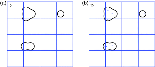
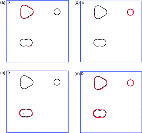
The first numerical simulation is concerned to reconstruct a peanut-shaped object, which is located at (0, 0), see the dark peanut in . Applying the parallel radial bisection algorithm in Section 2 to this example, we can first locate several interior points from the coarse mesh as mentioned previously, see the blue ones in . From the interior points we find in , we select one, see the blue one in . Finally, with the help of the selected interior point and a radius 20, we obtain the approximate boundary points of the peanut-shaped obstacle as shown in (see the red points).
Figure 3. (a) Interior points found in the first numerical simulation; (b) interior points found in the second numerical simulation; (c) exact (black) and reconstructed (red) peanut-shaped obstacle; (d) exact (black) and reconstructed (red) pear-shaped obstacle.
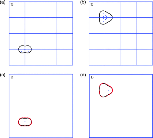
In the second simulation we investigate a pear-shaped obstacle located at (0, 10), see the dark pear in . Apply the parallel radial bisection algorithm to this case. Firstly, several interior points are located from the same coarse mesh in the first numerical simulation, see . From the interior points we found in , we select one, see the blue one in . Finally, with the help of the selected interior point and a radius 20, we obtain the approximate boundary points of the pear-shaped obstacle as shown in (see the red points).
The final numerical experiment for the acoustic obstacle model concerns a more complicated scatterer which contains three separated obstacle components, a ball, a peanut and a pear, see . Now we consider the sampling region D as [−6.3, 13.7] × [−6.3, 13.7].
We will first select a sampling mesh on the region D as shown in . We start with the illustration that the existing multilevel LSM Citation14 may fail to recover one or two obstacle components in this example. In fact, we can see from that there is only one obstacle which contains a mesh point, see the red grid point in . When we apply the multilevel LSM, and remove the so-called remote and inner cells at its first level, the two obstacle components, namely the ball and the peanut, are also removed. So multilevel LSM will be able to recover only one obstacle component among the three, namely the pear. Eventhough we refine the mesh in once, we will still miss the ball. So the multilevel LSM may need to start with a relatively fine mesh, thus increase the computational cost greatly. But our new parallel radial bisection method will be able to overcome such difficulty.
Now we use the parallel radial bisection algorithm to solve the complicated example. Firstly, we generate a coarse mesh as is shown in . Secondly, we find several interior points, see the blue ones in . Next we select three interior points from the interior points in , see the blue ones in , respectively. Thirdly, we find a set of approximate red boundary points for each select interior point which are shown in , where we observe that some separated boundary points may be found, e.g. one red point on both the ball and peanut in ; and three red points on the pear in . But we do not need to care about those separated points at this moment. Finally, we put all the approximate red boundary points together which yields the final approximate boundaries of the three components, see .
In the remainder of this section, we shall present some numerical examples with our PRBM for the second mathematical model, the shallow ocean waveguide model. As we will see, the algorithm works equally robustly and effectively as for the acoustic obstacle model.
The synthetic near-field data of the direct problem are generated by solving the double-layer potential operator equation with the boundary integral method Citation10, which converges with an order 𝒪(N−3). In the direct problem, the boundary of the scatterer is represented by 64 points {(r, θj)}, with θj = 2jπ/64, j = −31, −30, … , 32, and the source points (which are also detecting points) are located at (−30 + 0.5j, 2), j = 0, 1, … , 120. In the numerical experiments, 3% random white noise is added to the near-field data. For each relevant point z on the radii, the corresponding integral equation (1.4) is solved by the Tikhonov regularization method in combination with the Morozov discrepancy principle, and the regularization parameter equals to 10−8. The wave number is taken to be 3, the depth h of the shallow ocean environment is set to be 10 and the tolerance ϵ is chosen to be 10−5.
We will take the sampling region D as [−3, 3] × [3, 9], the mesh size of the coarse mesh is 3, so we have a total of 9 grid points on the coarse mesh. We always choose 10 radii corresponding to the each coarse mesh point for finding the interior points, and all the radii are evenly distributed in the circle. The number of radii on the selected circle is always set to be 50, and all the radii are evenly distributed along the circle.
The first experiment investigates a floriform scatterer, see the dark obstacle in , whose boundary can be parametrized by
where r = 0.5(1 − 0.6 sin(3θ)), 0 ≤ θ ≤ 2π.
Figure 6. (a) Interior points found in the first experiment; (b) interior points found in the second experiment; (c) exact (black) and reconstructed (red) floriform obstacle; (d) exact (black) and reconstructed (red) heart-shaped obstacle.
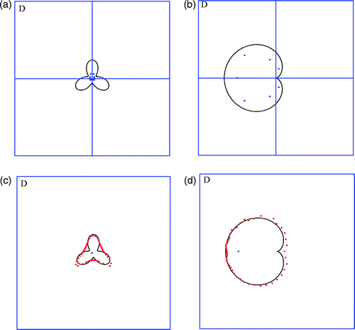
Apply the parallel radial bisection algorithm to this example. Firstly, we find several interior points from the coarse mesh as mentioned previously, see the blue ones in . Select one interior point, see the blue one in . Finally, with the help of the selected interior point and a radius 5, we obtain the approximate boundary points of the floriform obstacle as shown in (see the red points).
In the second experiment, we consider a heart-shaped object embedded in the region D, see the dark object in the . The boundary of the scatterer can be parametrized as
where r = 1 − cos(θ), 0 ≤ θ ≤ 2π. As before, we apply the parallel radial bisection algorithm to this case. Firstly, several interior points are found from the coarse mesh as mentioned previously, see the . Select one interior point, see the blue one in . Finally, with the help of the selected interior point and a radius 5, we obtain the approximate boundary points of the heart-shaped obstacle as shown in (see the red points).
Finally, we compare the computational times of the LSM, the MLSM, and the PRBM, which are listed in .
Table 1. Computational times of the the acoustic obstacle model.
The comparison of the GDSIM and the PRBM is shown in .
Table 2. Computational times of the shallow ocean waveguide model.
As we see from and , the parallel radial bisection algorithm outperforms the classical LSM, the multilevel LSM and the GDSIM essentially.
At last, we compare the theoretic computational time for solving the integral equation and the theoretic storage for the sampling points of the previous methods in .
Table 3. Comparison of the computational time and storage.
4. Conclusion
A novel PRBM is proposed for the reconstruction of scatterers from either far-field or near-field measurements. Both the analysis and the numerical simulations have demonstrated the robustness and the optimal computational complexity of the algorithm. The new method is easy to implement, and can essentially reduce the computational cost of the indicator type reconstruction methods such as the LSM, the MLSM and the GDSIM, without deterioration of the quality of the reconstruction. In addition, this new method can be equally applied to inverse electromagnetic obstacle scattering.
Acknowledgements
The work of this author was substantially supported by Hong Kong RGC grants (Projects 405110 and 404611).
References
- Colton, D, and Kress, R, 2006. Using fundamental solutions in inverse scattering, Inverse Probl. 22 (2006), pp. R49–R66.
- Potthast, R, 2006. A survey on sampling and probe methods for inverse problems, Inverse Probl. 22 (2006), pp. R1–R47.
- Erhard, K, and Potthast, R, 2006. A numerical study of the probe method, SIAM J. Sci. Comput. 28 (2006), pp. 1597–1612.
- Ikehata, M, 1998. Reconstruction of the shape of the inclusion by boundary measurements, Commun. Partial Differ. Eqns 23 (1998), pp. 1459–1474.
- Potthast, R, 2001. Point Sources and Multipoles in Inverse Scattering Theory. Vol. 427. London: Research Notes in Mathematics, Chapman & Hall/CRC; 2001.
- Colton, D, and Haddar, H, 2005. An application of the reciprocity gap functional to inverse scattering theory, Inverse Probl. 21 (2005), pp. 383–398.
- Colton, D, and Kress, R, 1998. Inverse Acoustic and Electromagnetic Scattering Theory. Berlin: Springer-Verlag; 1998.
- Cakoni, F, and Colton, D, 2006. Qualitative Methods in Inverse Scattering Theory. Berlin: Springer-Verlag; 2006.
- Cakoni, F, Colton, D, and Monk, P, 2001. The direct and inverse scattering problem for partially coated obstacles, Inverse Probl. 17 (2001), pp. 1997–2015.
- Colton, D, and Kirsch, A, 1996. A simple method for solving inverse scattering problems in the resonance region, Inverse Probl. 12 (1996), pp. 383–393.
- Xu, Y, Mawata, C, and Lin, W, 2000. Generalized dual space indicator method for underwater imaging, Inverse Probl. 16 (2000), pp. 1761–1776.
- Xu, Y, 1990. The propagating solution and far field patterns for acoustic harmonic waves in a finite depth ocean, Appl. Anal. 35 (1–4) (1990), pp. 129–151.
- Xu, Y, and Yan, Y, 1993. An approximate boundary integral method for acoustic scattering in shallow oceans, J. Comput. Acoust. 1 (1993), pp. 61–75.
- Li, J, Liu, H, and Zou, J, 2008. Multilevel linear sampling method for inverse scattering problems, SIAM J. Sci. Comput. 30 (2008), pp. 1228–1250.
- Buchanan, J, Gilbert, R, Wirgin, A, and Xu, Y, 2004. "Marine Acoustics: Direct and Inverse Scattering of Waves". In: Other Titles in Applied Mathematics. Philadelphia: SIAM; 2004.
- Li, J, Liu, H, and Zou, J, 2009. Strengthened linear sampling method with a reference ball, SIAM J. Sci. Comput. 31 (2009), pp. 4013–4040.
