Abstract
A method of solution of the inverse problem in heat conduction is presented. The method, based on an adjoint optimization procedure, is applied to the design of the pattern of circular cooling passages inside coated turbine blades. The general case of a non-homogeneous solid material is considered. The numerical solution of both the temperature field and the adjoint problem is based on a finite element method. The mathematical method is explained and the procedure is validated against theoretical and experimental data available in open literature.
1. Introduction
A wide range of engineering problems in thermal analysis and design has been formulated as inverse heat transfer problems Citation1. The inverse problem involves the estimation of the cause by utilizing the knowledge of the effect. Several studies focus on the cause–effect relation between heat flux and temperature. A classical example of this class of inverse problems deals with the estimation of an unknown boundary heat flux, by using temperature measurements taken below the boundary surface. Other studies estimate the steady or unsteady inlet temperature profile, or cover aerothermal effects by estimating steady/transient wall heat flux in laminar flow, or deduce inlet velocity estimation based on the temperature measurements. For conciseness, the interested reader can refer to Citation1–6 and the references therein. In fact, the abovementioned problems are out of the scope of this present work, which belongs to the class of the design problems.
The design problem can be formulated as an inverse problem in which some conditions are given at the boundary, while the shape of the body contour that realizes the imposed thermal features is unknown. Applications of this approach to heat conduction design problems have been proposed and successfully applied to turbine blade cooling in the past three decades. The heat conduction inverse problem of the geometry design of the internal cooling passages of a turbine blade has been solved for circular Citation7, super-elliptic Citation8 and generic geometries of the cooling passages in multi-holed turbine blade Citation9,Citation10. The numerical procedures are mainly based on a direct solver driven by an optimization method. In one of the earliest applications Citation7, a boundary element method for heat conduction analysis and a gradient method, the steepest descent method (SDM) have been used to converge to the inverse problem solution. After that, the exponential growth of computational resources has allowed for an extensive use of more flexible and CPU consuming numerical approaches. Solvers based on finite element method (FEM) or finite volume method in two and three dimensions have been used to evaluate the thermal field, while, in the modelization of the physics, the convection and radiation effects have been included. Then the research evolved to conjugate heat transfer analyses by including the mutual interactions with the fluid flow and by modelling film cooling effects Citation11.
From the optimization counterpart, the improvements of gradient-based methods have led to the various formulations by adjoint methods for 2D/3D problems Citation10,Citation12,Citation13, while the use of genetic algorithms has also been introduced for the solution of the single objective and multi-objective optimization problems.
A new impulse to thermal design in aerospace propulsion is related to recent efforts of designing aeroengines which meet the Vision 2020 requirements on gasturbine emissions and efficiency from Advisory Council for Aeronautics Research in Europe. A straight way to enhance efficiency is obtained by increasing the maximum cycle temperature, i.e. the temperature into the combustion chamber. Moreover, other investigations introduce the interstage turbine burner concept to modify the thermodynamic cycle during flight, going towards variables cycle aeroengines. In both approaches, a closer control of the temperatures is required and the thermal design of the some engine components, as the burners and the turbine blades, becomes more aggressive. In this scenario, automated inverse problem solvers can help the designer to make choices based on a wider investigation of the design variables space.
In this work an approach to inverse problem solution is proposed. The method is based on the adjoint optimization and follows the footsteps of a technique of aerodynamic design Citation14,Citation15. The mathematical treatment of the adjoint problem differs from previous adjoint approaches (see, e.g. Citation10,Citation13). In fact, the proposed formulation does not need a sensitivity problem to be solved and it includes a penalization for imposing geometrical constraints. To allow for the treatment of coated blades, the heat conduction equation in a non-homogeneous material has been considered. As first step, circular cooling passages are treated and a way to impose non-intersecting contour constraints is developed. An FEM approach has been used both to compute the thermal field inside the turbine blade and to solve for the adjoint problem. The plan of this article is as follows: in the next section the mathematical model and the inverse problem solution are presented; then the adjoint problem is derived and the numerical technique is explained. Finally the geometric parametrization of the blade cooling passages is derived and the procedure is validated against an analytical solution and against a test case based on experimental data available in the open literature.
2. Governing equations and inverse problem formulation
Let us consider the heat conduction equation in a non-homogeneous material and Robin boundary conditions. This set of equations may be written in a compact integral conservative form as
(1)
(2)
(3)
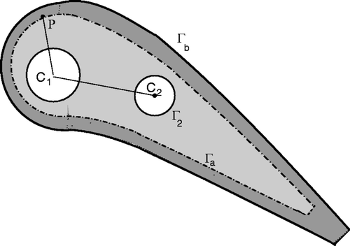
where T is the temperature, Tg and Tcj are gas and coolant flow temperatures, h is the heat transfer coefficient and n is outward normal vector. For the thermal conductivity, we pose k = k(x) as a function of position vector x. In fact, in turbine blades with ceramic coating one can distinguish at least two regions with very different k-values. A sketch of a generic domain is shown in . Γb is the external surface of the turbine blade, Γa is the interfacial surface between inner core blade (light grey) and coating material (dark grey), and Γc is the union of the Γj surfaces of the N inner cooling passages. In the classical thermal inverse problem, the boundary shape of the cooling passages Γj is regarded as unknown while some field variables are known at the external boundary Γb.
In the literature, whatever the method of solution used, various choices have been adopted in formulating the inverse problem. In Citation9, both the heat flux and the temperature are imposed in a discrete set of points on Γb. In Citation7, the temperature on Γb is imposed and the geometry that realizes a target heat flux distribution in Γb is sought for. In Citation10, mixed boundary conditions are imposed on both Γb and Γj, while looking for the geometry of the cooling passages that realizes the desired temperature in a discrete set on points on Γb. In this work, the approach is similar to the latter case, which is in our opinion the most suitable for a straight application, as well as for the experimental validation. We impose Robin boundary conditions both on the external blade surface Γb and on the internal cooling passages Γj, here supposed of circular shape, and we use the adjoint-based gradient method to find the hole locations and diameters which realize a desired temperature distribution Tb(x) along the boundary Γb. In this work, the temperature distribution Tb(x) is a known function related to a designer choice.
The numerical solution of system (1) is based on the FEM. The derivation of steady conduction equation is a standard exercise in classical textbook on FEM and will not be repeated here. As a guideline and using the terminology and notation of Citation16, pp. 87–92], let us assume for the temperature field the form
(4)
where [N] = {N1, Ni, … , Nr} is the shape function matrix and {T } = {T1, Ti, … , Tr}T the nodal temperature vector. Equations (1) can be reduced to
(5)
where
(6)
(7)
with
(8)
The system (3) may be linear or not, depending on the expressions of [K] and { f }. The parallel version of the SPOOLES package has been used to solve system (3).
The inverse problem is solved as an optimization problem, as outlined in the following section. The procedure iterates on a series of direct computations until all boundary condition and constraints are satisfied within an expected range of gradient and cost function residuals.
3. Variational formulation, adjoint equation and gradient
We define the cost function
(9)
where the 𝒫(Γc) is a penalization function added to enforce the geometric constraints to the optimization problem. The control variable is the set of relations defining the cooling passages geometry Γc. In two dimensions, each boundary has a parametric representation as follows:
(10)
where pj(s), qj(s) are shape functions and μj, νj are the control parameters that can be packed in a single vector αi.
The optimal temperature field must satisfy the governing equation (1) and some geometric constraints. In order to solve such constrained extremum problem we introduce the Lagrangian function
(11)
where Λ(x) is a Lagrange multiplier. The Lagrangian will allow us to treat the problem as unconstrained. A stationary configuration is found when the variation of ℒ with respect to all its arguments, that are now considered independent functions, is 0. We compute δℒ as
(12)
All the contributions to δℒ must be 0 at the minimum. Hence, to find a stationary point we enforce
In general this results in
. To reach the minimum we take δΓj such that
.
Note that the variations of ℒ with respect to the Lagrange multipliers Λ simply yield the heat conduction equation. The condition δℒT = 0 leads to the adjoint equation and its boundary conditions. Based on the second Green's identity the second integral can be formulated as
(13)
By perturbing the boundary conditions (1b,1c) we can write
(14)
Substituting in (11) and considering all this integral contributions must vanish, we have
(15)
The adjoint problem (13) is formally identical to system (1). By changing Λ ← T and with slight modifications to the set of boundary conditions, the numerical method used to solve the thermal problem can be applied to the adjoint problem.
To derive the variations we observe that, from Equation (8) they are formally equivalent to (and therefore replaced by) the variations of the Lagrangian function against the control parameters αi
(16)
where
(17)
The final expression of the terms 𝒢i(Γi, T, Λ) depends on the adopted parametrization of the cooling passages geometry. The formulation of 𝒢i for circular cooling holes is derived in Section 3.1. If we update αi with
(18)
by taking ρ > 0, then δℒα ≤ 0. By iterating such a procedure, the minimum is eventually reached. This method, namely the SDM, has a slow convergence. Better convergence rates can be obtained with the conjugate gradient method (CGM), in which the correction δα at the iteration n is given as
(19)
where βn is defined by the modified Polak–Ribière formula
(20)
3.1. Geometric parametrization and constraints
The objective of this section is to derive a formulation of 𝒢i able to parametrize the geometric optimization variables αj and to include the necessary set of constraints.
We consider M circular cooling passages. The boundary of each passage is defined by
(21)
where C = (aj, bj), Rj are the centre and radius of the j-th circle, respectively.
For the sake of conciseness, the set of control variables aj, bj, Rj can be collected into a single vector αi of 3M elements defined as
(22)
The hole boundaries cannot intersect each other and must lie far from the coating region of the blade. These requirements are constraints of the optimization problem and are introduced using penalization. In a way similar to Citation7, considering M coolant passages, we write the penalization function as
(23)
where
(24)
is the minimum distance between the i-hole surface and the Γa contour (see ), and
(25)
is the minimum distance between two coolant passage contours Γi and Γj. The complete set of derivatives is
(26)
and
(27)
Finally, we derive the expression for the variation of the Lagrangian function with respect to the parametrization.
Letting a variation αi ← αi + δαi, neglecting higher order terms, the functional 𝒢i can be reduced to
(28)
where the derivative of the penalization function 𝒫 are given by Equations (24) and (25). Note that in Equation (20) the vector αi is composed by three set of control variables aj, bj, Rj, therefore we are now led to a formulation of 𝒢i in which the three different contributions have been distinguished.
4. Numerical results
The proposed numerical procedure is a classical optimization approach based on the adjoint equation to compute the functional gradient. Basically it consists of the following steps:
| 1. | solve the direct problem (1), | ||||
| 2. | solve the adjoint problem (13), | ||||
| 3. | evaluate the functional gradient (14), | ||||
| 4. | compute the conjugate direction of search via (17) and march towards the extremum, | ||||
| 5. | update the solution and test the convergence criterion | ||||
4.1. Coated cylinder with internal heating
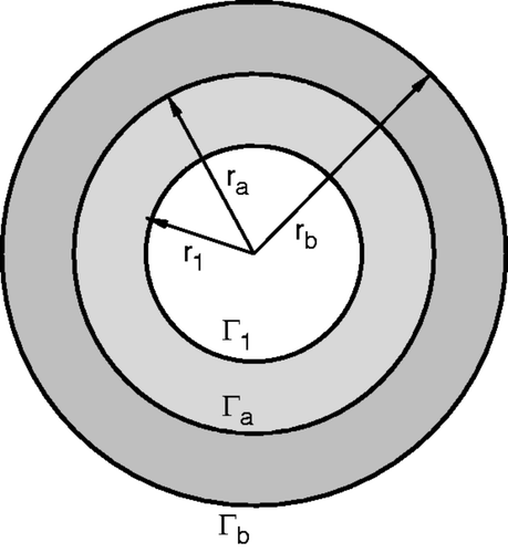
Let us consider the heat transfer problem on a composite hollow cylinder with coating and a single circular heating passage as shown in . The cylinder radii are rb = 58, ra = 38, r1 = 25 mm. The inner flow has a temperature Tc = 603.15 K, while the temperature of the external gas flow is Tg = 303.15 K. The thermal conductivities of the inner core and of coating are k1 = 15 and k2 = 0.2 W m−1 K−1, respectively.
Robin boundary conditions have been applied by specifying the heat convection rates for the inner flow passage (hc = 400 W m−2) and for the exterior cylinder surface (hg = 60 W m−2). The exact solution of the temperature field on the whole domain is obtained by classical analytical methods and it can be found in Citation18, p. 63, Example 3–11].
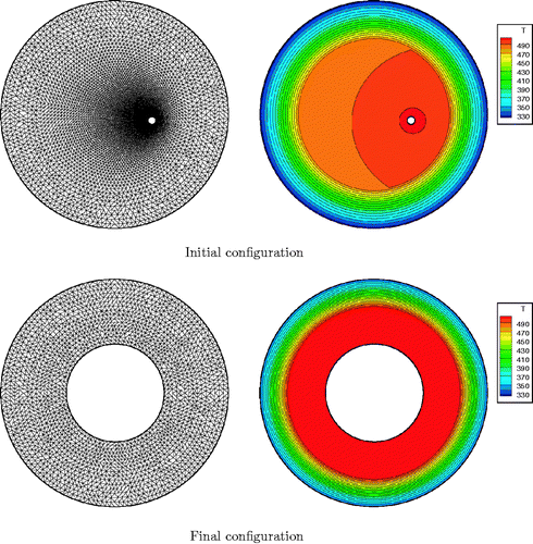
The inverse problem proposed here is inspired to a similar test case found in Citation7. From the knowledge of the temperature Tb(Γb) on the external cylinder surface, the correct geometry of the system is sought. Starting from a generic geometric configuration for the cylinder, as shown in , we solve for the location and radius of the heating passage that realizes the target external wall temperature Tw = Tb(Γb) (= 337.230 K).
The problem parametrization follows the guidelines given in Section 3.1. The control variables are
i.e. the centre coordinates and the radius of the inner circular hole, respectively. The thermal field and the related adjoint problem are then solved at each optimization step and the domain geometry is updated following Equation (17) by the CGM strategy. We used parabolic triangular finite element. Adaptive mesh refinement with error control is obtained by using the bamg meshing and adaptation tool Citation19. Since the computational cost of the procedure still remains affordable, a very crude meshing strategy has been adopted. By a grid sensitivity analysis, an adequate level of mesh refinement is found in the initial computational domain. At each optimization step then:
| 1. | The domain geometry is derived from the parametrization used and the grid is generated. | ||||
| 2. | The thermal field is computed by the FEM solver. | ||||
| 3. | This solution is used to generate a new adaptivemesh by bamg meshing tool. | ||||
| 4. | The thermal field and gradient are computed on the second mesh. | ||||
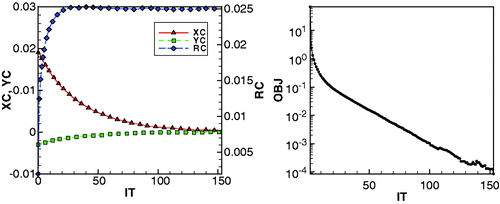
Initial and final temperature field and geometry are shown in . The system has shown a fast and monotonic convergence. In , the control variables αi and the functional residuals versus the optimization steps are plotted. As visible, after 20 iterations the functional residual is decreased of three orders of magnitude, even if a penalization has been applied. It must be noted, anyway, that there were very few control variables and that the influence of the penalty function was limited to the mitigation of asymmetric variations of the gradient components.
Figure 4. Test 1: convergence history of xc = a1, Yc = b1, Rc = r1 (left) and of the objective function residuals (right) vs. optimization step.
A comparison between numerical and analytical results is given in . The close agreement between data confirms the high resolution of the computations: the highest relative error is below 0.3%. We also note the remarkable accuracy of the heat flux computation, which involves a derivative evaluation and therefore was supposed to be more prone to numerical error. Moreover, the heat flux is a dependent variable which plays a key role on the system since it is imposed as boundary condition.
Table 1. Composite hollow cylinder test. Comparison between numerical and theoretical value of main parameters.
4.2. Mark II turbine blade
Experimental data about the Mark II and CF3X internally cooled turbine blades are available in the open literature Citation17 and have been used as a reference test case in several work, on the conjugate heat transfer and optimal blade design. The Mark II stator vane geometry is depicted in . The cooling system of this blade is composed by 10 circular passages (M = 10). In the original work a method of evaluating the heat transfer coefficient is outlined and the experimental results (wall pressure, blade surface temperature and heat flux coefficient) are given for a wide range of working conditions. Walking on the footsteps of the previous section, the experimental data are used here to formulate a design problem and to solve it by the inverse numerical procedure. The measured surface temperature for a selected working condition (namely, the run-15) is assumed as target temperature Tb(x). Then, starting from an arbitrary initial geometry, the correct coolant passage pattern is sought by solving the adjoint inverse problem.
First, we define the expression for the heat coefficients. For the coolant passages, the expression of the Nusselt number given in Citation17 is used
(29)
where Pr and Re are the Prandtl and Reynolds numbers based on the coolant flow rate, viscosity and temperature. Cr is an empirical correction parameter introduced in Citation17.
For the external blade surface a polynomial approximation of the heat transfer coefficients has been computed by fitting and smoothing the experimental data. The curve obtained is shown in . Again, the control variables are the centre coordinates and radii of the circular cooling passages. These variables has been packed as
Starting from the generic initial condition depicted in , the inverse procedure has been applied until a satisfactory level of convergence is reached. The converged solution and temperature field are shown in , while the experimental and the evaluated blade surface temperature are compared in . The convergence of the objective functional and of the L2-norm residual of controls αi is monitored in .
Figure 5. Test Mark II: initial (a) and final (b) grid and cooling passage pattern, initial (c) and final (d) temperature field.
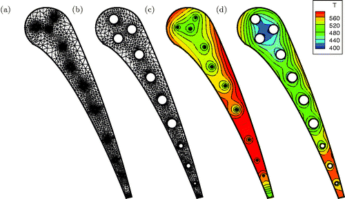
Figure 6. Test Mark II: heat transfer coefficient fitting (left) and comparison of the surface temperature obtained by the inverse problem and the target temperature distribution (right). Note: Symbols refer to the experimental data and solid lines to numerical results).
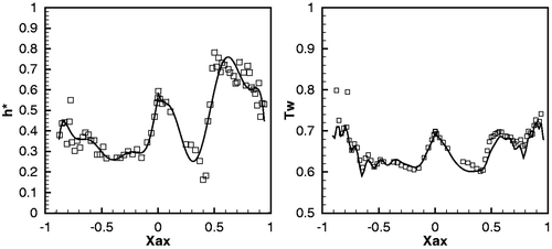
Figure 7. Test Mark II: convergence history of L2-norm of gradient residuals (left) and of the objective function residuals (right) vs. optimization step.
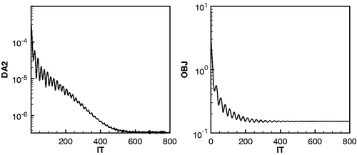
Although this test being quite severe (there are 30 control variables and strong penalty functions), the geometrical configuration obtained is close to the real one. For each αi the relative error is less than 0.5%, a value slightly bigger than the error observed in the previous test T1.
It has also been observed that the penalization effect is twofold: it reduces the convergence rate dramatically and makes the solution less sensitive to the original objective functional. In the present case, it acts also as a smoothing filter for the target temperature peaks and experimental noise. Nevertheless, by using a parallel implementation of the FEM code, the full computation has run in about 1 h on a 8-core Intel i7 workstation.
5. Conclusions
An adjoint procedure for the solution of the inverse heat conduction problem has been proposed. Compared to similar approaches, the present method does not require the evaluation of an additional perturbation field and the functional gradient with respect to the control variables is computed from its parametrization. This simplification is supposed to increase the robustness of the whole numerical procedure.
The procedure has been validated against analytical and experimental solutions. The numerical tests carried out have shown an acceptable convergence rate, even if as much as 30 control variables were treated and a strong penalization is applied to avoid intersections between adjacent coolant flow passages or between a coolant passage and the external surface of the blade. The penalization is supposed to be responsible for the convergence worsening. In fact, it is well known that the number of control variables does not affect the performances of adjoint procedures. Nevertheless the computational cost is affordable on a medium level workstation.
The method has been specialized to the case of blade with circular passages holes. The extension to other geometries and to the three-dimensional case is straightforward but at the cost of 3D FEM computations and of a more complex parametric representation. From the numerical point of view a general purpose FEM engine can be used to solve both the thermal and the adjoint problem. Therefore, the method can be implemented in any free or commercial FEM engine that allows to impose user defined function as boundary conditions. Work on improvements on the grid adaptation strategy and on the parametrization of actual geometries of multi-holed turbine blades is in progress. In future work, the transient heat conduction/convection should be considered in the optimization procedure as a route to robust design and turbine blades life enhancement.
References
- Necati Özisik, M, and Orlande, HRB, 2000. Inverse Heat Transfer. London: Taylor & Francis; 2000.
- Colaco, MJ, Orlande, HRB, and Dulikravich, GS, 2006. Inverse and optimization problems in heat transfer, J. Braz. Soc. Mech. Sci. Eng. 28 (1) (2006), pp. 1–24.
- Szczygiel, I, and Fic, A, 2002. Inverse convection-diffusion problem of estimating boundary velocity based on internal temperature measurements, Inverse Probl. Eng. 10 (2002), pp. 271–291.
- Beck, JV, Blackwell, B, and St. Clair, C, 1985. Inverse Heat Conduction: Ill-posed Problems. New York: Wiley; 1985.
- Alifanov, OM, 1994. Inverse Heat Transfer Problems. Berlin: Springer-Verlag; 1994.
- Kurpisz, K, and Nowak, AJ, 1995. Inverse Thermal Problems. Southampton, UK and Boston, MA: Computational Mechanics Publications; 1995.
- Chiang, TL, and Dulikravich, GS, 1986. Inverse design of composite turbine blade circular coolant flow passages, ASME J. Turbomach. 108 (1986), pp. 275–282.
- Dulikravich, GS, and Martin, TJ, 1994. Inverse design of super-elliptic cooling passages in coated turbine blades, Int. J. Thermophys. Heat Transfer 8 (2) (1994), pp. 288–294.
- Kennon, SR, and Dulikravich, GS, 1985. The inverse design of internally cooled turbine blades, ASME J. Eng. Gas Turbines Power 107 (1985), pp. 123–126.
- Huang, CH, and Hsiung, TY, 1999. An inverse design problem of estimating optimal shape of cooling passages in turbine blades, Int. J. Heat Mass Transfer 42 (1999), pp. 4307–4319.
- Montomoli, F, Adami, P, and Martelli, F, 2009. A finite-volume method for the conjugate heat transfer in film cooling devices, Proc. IMechE. Part A: J. Power and Energy 223 (2009), pp. 191–200.
- Huang, CH, and Chen, CW, 1998. A boundary element based inverse-problem in estimating transient boundary conditions with conjugate gradient method, Int. J. Numer. Methods Eng. 42 (1998), pp. 943–65.
- Huang, CH, and Wang, SP, 1999. A three-dimensional inverse heat conduction problem in estimating surface heat flux by conjugate gradient method Int, J. Heat Mass Transfer 42 (1999), pp. 3387–3403.
- Iollo, A, Ferlauto, M, and Zannetti, L, 2001. An aerodynamic optimization method based on the inverse problem adjoint equations, J. Comput. Phys. 173 (2001), pp. 87–115.
- Ferlauto, M, Iollo, A, and Zannetti, L, 2004. Set of boundary conditions for aerodynamic design AIAA J. 42 (8) (2004), pp. 1582–1592.
- Lewis, RW, Nithiarasu, P, and Seetharamu, KN, 2004. Fundamentals of the Finite Element Method for Heat and Fluid Flow. London: Wiley & Sons; 2004.
- Hylton, LD, Millec, MS, Turner, ER, Nealy, DA, and York, RE, 1983. Analytical and Experimental Evaluation of the Heat Transfer Distribution Over Surface of Turbine Vanes. CR 168015: NASA-Report; 1983.
- Necati Özisik, M, 1985. Heat Transfer, A Basic Approach. London: McGraw-Hill; 1985.
- Hecht, F, and Kuate, R, 2008. "Metric Generation for a Given Error Estimation". In: Rao Garimella, V, ed. Proceedings of the 17th International Meshing Roundtable. Berlin: Springer; 2008. pp. 569–584.
