 ?Mathematical formulae have been encoded as MathML and are displayed in this HTML version using MathJax in order to improve their display. Uncheck the box to turn MathJax off. This feature requires Javascript. Click on a formula to zoom.
Abstract
The inverse scattering problem in two-layered background that arises in near-field optics is discussed. The reconstruction of the scatterer from inhomogeneous medium deposited on a homogeneous substrate is presented, where the measured data only lies on a limited aperture. An error bound of the Born approximation is given. A moment method with truncated SVD is developed to handle the exponentially ill-posed problem with noisy measured data. Numerical experiments are presented to illustrate the resolution of the method, which are satisfying even under the perturbed data.
1 Introduction
We can obtain images with subwavelength resolution via evanescent wave field in near-field optics.[Citation1] There are three important modalities in near-field optics : near-field scanning optical microscopy (NSOM),[Citation2] total internal reflection microscopy (TIRM)[Citation3, Citation4] and photon scanning tunnelling microscopy (PSTM).[Citation5, Citation6] The two principal genres of NSOM are illumination mode and collection mode. In illumination mode NSOM, a probe is scanned over the scatterer in the near zone and the scattering field is measured in the far zone of scatterer. In collection mode NSOM, the scatterer is illuminated by a source located in the far zone of the scatterer and the total field is collected in the near zone of the scatterer through the small aperture in the probe as the probe is scanned over the scatterer. In TIRM, the scatterer is illuminated by an evanescent wave that is generated by total internal reflection, and the scattering field is measured in the far zone of the scatterer. In the PSTM, the scatterer is illuminated by an evanescent wave and the scattering field is measured in the near zone.
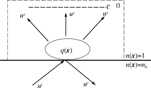
Figure 1. The geometry of the model problem. The scatterer is in a compact support in
, the measurements are taken on
and
is a compact set containing
and
.
In all of the three modalities, reconstruction of the scatterer from the measured data is desirable. In [Citation1], within the framework of weak scattering, the authors give some numerical experiments to recover the scatterer. Bao and Li developed a recursive linearization method from an initial guess based on weak scattering. In [Citation7], the model problem employs the first-order boundary condition, and requires the boundary measurements of scattering waves, but it only needs single-frequency incident wave. In [Citation8], the radiation condition is employed, and it requires multi-frequency incident waves. The model in [Citation8] uses a limited aperture data.
In this paper, we adopt the model with radiation condition, single-frequency incident wave and a limited aperture data. We will give an error estimate of the inverse problem. In [Citation9], the authors deal with an optical diffusion problem, and give an inversion of the linear problem, but the computation is limited by the numerical precision, for its ill-posedness. Due to the ill-posedness of the inverse problem, we develop an effective numerical method: moment method with truncated SVD (singular value decomposition).
This paper is organized as follows. In Section 2, we give a mathematical model of the scattering problem. Next, based on the work of Schotland [Citation10, Citation11], etc., the inverse problem is discussed. In Section 3, we discuss the regularization of the linearized problem. We present the moment method with truncated SVD, in order to handle the severely ill-posed problem with noisy measured data. Numerical examples are presented in Section 5 and some remarks are concluded in the final section.
2 Scattering and inverse scattering problem
2.1 Scattering problem
We describe the scattering model mathematically as follows. Assume that the materials are nonmagnetic in the problem considered in this paper. Throughout, we only consider the problem which can be reduced to a two-dimensional model in the case of transverse electric polarization. The index of refraction in the lower half-space has a constant value . The index of refraction in the upper half-space varies within the domain of the sample but otherwise has a value of unity.[Citation1, Citation8] That is, the background media consists of two layers with the index of refraction
where
and
.
We denote the scatterer by within a compact support in
, with
the susceptibility of the scatterer.[Citation1] The incident wave comes from the lower half-space, which is a time-harmonic plane wave
where
and
is the free space wavenumber. The geometry of the model problem is shown in Figure . The measurements are taken on
, and
is a compact set containing
and
.
Figure 2. Direct discretization method and Tikhonov regularization of problem (Equation4.14.1
4.1 ).
![Figure 2. Direct discretization method and Tikhonov regularization of problem (Equation4.14.1 g(t)=∫01e-tsf(s)ds,t∈[0,1],4.1 ).](/cms/asset/85f520b8-d9f9-4f98-befe-a4a5ff5eda23/gipe_a_890611_f0002_oc.gif)
Figure 3. Moment method and moment method with truncated SVD for problem (Equation4.14.1
4.1 ).
![Figure 3. Moment method and moment method with truncated SVD for problem (Equation4.14.1 g(t)=∫01e-tsf(s)ds,t∈[0,1],4.1 ).](/cms/asset/4253cf7d-43a8-412a-9e68-1c77d1f00beb/gipe_a_890611_f0003_oc.gif)
It is easy to check that the total field satisfies the Helmholtz equation
2.1
2.1 Let
be the reference field, which satisfies the Helmholtz equation without the scatterer:
2.2
2.2 From Equation (Equation2.2
2.2
2.2 ) and the continuity condition on the interface we can analytically obtain that
where
are the transmitted and reflected waves, respectively, [Citation8, Citation12, Citation13], and
It can be readily seen that the transmitted wave
becomes evanescent wave when
. That is,
decays exponentially in the
direction.
Define the scattering field . Then from (Equation2.1
2.1
2.1 ) and (Equation2.2
2.2
2.2 ), we have
2.3
2.3 And we require the radiation condition [Citation8, Citation14]
2.4
2.4 where
is the sphere centred in the origin with radius
, and
is the unit outward normal to
.
Now we introduce the fundamental solution of the Helmholtz equation in a two-layered medium in
, which satisfies
2.5
2.5 with radiation condition, and the continuity conditions
2.6
2.6
2.7
2.7 By use of fundamental solution, we can give the formula
2.8
2.8 which is well known as Lipmann-Schwinger equation.
Furthermore, if we define and
by
2.9
2.9 and
2.10
2.10 respectively, then we have that
2.11
2.11 when
and
.(see [Citation8])
We rewrite (Equation2.82.8
2.8 ) in an operator form:
2.12
2.12 where the operator
is defined as follows:
2.13
2.13 If
,
exists and is bounded in
norm. We can express
by the Neumann series
2.14
2.14
Remark 1
In fact, here can be split into two parts:
where
It is easy to see that
.[Citation15]
In [Citation16], the authors proved that, for is a bounded operator from
to
.
So, the operator is also bounded from
to
. And when
and
are sufficiently small, the assumption
is valid.
2.2 Inverse scattering problem
The inverse scattering problem considered in this paper is from some model of near-field optics. In these problems, the measurements of scattering wave are given on
. The inverse problem is to determine
. In particular, the shape of support of
is easy to be seen after that
is determined.
Because the operator is linearly in
, our inverse problem can be written as: finding
to satisfy
2.15
2.15 where
and
defined by
and so on.
For , we have that
2.16
2.16 where
2.17
2.17 and
2.18
2.18 By Denoting
as the regularized pseudo-inverse of the operator
, we have the following result from [Citation11] and [Citation17]:
Theorem 2.1
Suppose that . Let
and assume that
. Then the norm of the difference between the true scatterer and the linearized inverse solution obeys the estimate
2.19
2.19 where
and
are independent of
.
Theorem 2.1 gives the error estimate of the inverse problem concerning Born approximation. The first error term in (Equation2.192.19
2.19 ) relates much to the the norm of
. And the second term describes the error between the exact solution and the regularized solution of the linearized problem with
being the measured data.
So the construction of is very important to the inverse scattering problem. However, the equation
is difficult to solve, for its severe ill-posedness. Few work has been done for the detailed numerical methods of this severely ill-posed problem and its error estimate, which we will discuss in the next section.
Remark 2
When ,
and
are sufficiently small, the assumption
is valid, and
are also sufficiently small.
We checked numerically that ,
are very small. Therefore, the assumptions in Theorem 2.1 could be satisfied, and the first term in (Equation2.19
2.19
2.19 ) would also be small.
3 Numerical method for the linearized inverse problem
The linearized inverse problem, as discussed in pervious section, is3.1
3.1 more explicitly,
3.2
3.2 Note that the only known data lie on the segment
, so we extend
on
to the whole line
by defining
on the remaining interval of
. We assume that the error between the expanded data
and the “exact” data is small when
is sufficiently large. Namely, we assume that
, where
depends on
. The scattering data
depends on
, and we need several different incident waves, i.e. we need
to reconstruct the scatterer
.
Thus, we have3.3
3.3 Substituting the fundamental solution
and
into (Equation3.3
3.3
3.3 ) and realizing the dependence of
on
, we rewrite (Equation3.3
3.3
3.3 ) as
3.4
3.4 Multiplying both sides of (Equation3.4
3.4
3.4 ) by
and integrating from
to
with respect to
,
3.5
3.5 and noting that
(Equation3.5
3.5
3.5 ) can be rewritten as
3.6
3.6 Realizing that
(Equation3.6
3.6
3.6 ) can be reduced to
3.7
3.7 When
and
, both
and
are real; and for
,
is pure imaginary, and so is
with
. It is obvious that the inversion of (Equation3.7
3.7
3.7 ) involves both inverse Fourier transform and inverse Laplace transform. In fact, both inverse Fourier transform and inverse Laplace transform defined on finite interval are ill-posed, especially the inverse Laplace transform is exponentially ill-posed.[Citation18]
In [Citation9], the authors used a method that is essentially the moment method to handle the inversion of an optical diffusion problem. They simulated their problem in the two-dimensional case, but the resolution is limited by numerical precisions.
Here, we split the two-dimensional problem (Equation3.73.7
3.7 ) into two one-dimensional problems. So, the computation runs much faster and uses less memory. Moreover, we apply the moment method with truncated SVD to get a better resolution where the limitation of numerical precisions is circumvented in a certain extent.
We need two steps to solve (Equation3.73.7
3.7 ).
| Step 1 | For | ||||
| Step 2 | Obtain | ||||
The first step is to solve the operator equation for every specified .
3.8
3.8 where
3.9
3.9 Denote
then
is a compact operator since
.
Let be finite-dimensional subspaces with
and
be the collocation points, which are chosen as
. Then the collocation equation is
3.10
3.10 where
then
is a collocation solution of (Equation3.10
3.10
3.10 ).
Choosing a basis of
then
can be represented as
where the coefficients
’s are the solution of the system
3.11
3.11 with
For ill-posed problems such as (Equation3.11
3.11
3.11 ), even small perturbation of data
can change the solution a lot. Recall that we can only obtain the scattering data on
, and we have assumed that
. Now we denote the perturbed data, or the measured data, by
, and let
, where
takes in the influence of the error bound
, and
denotes Euclidean norm in
Remark 3
In fact, there is no need that the number of measurements points coincides that of the collocation points. In [Citation19], a proper interpolation method can be made to obtain all the ’s ,
, from the measurements points
Solving (Equation3.103.10
3.10 ) in
cannot specify the solution
uniquely. There are several choices of the basis
’s. In this section, we will give an easy choice of the basis, and under this choice, we can obtain a unique solution.
We will find a moment solution of (Equation3.103.10
3.10 ), which means that
with respect to the collocation points
.
Recall Riesz theorem that there exists , such that,
, for all
, and
In particular for the integral operator
,
is explicitly given by
If
’s are linearly independent, i.e. the determinant of the collocation matrix
is not equal to 0, by choosing
, there exists one and only one moment solution
of (Equation3.10
3.10
3.10 ) (see [Citation20]).
However, the system of (Equation3.113.11
3.11 ) is severely ill-posed, so it is difficult to find a stable moment solution. We will apply the truncated SVD method to improve the stability of problem (Equation3.10
3.10
3.10 ).
Using SVD, we can writewhere
and
are unitary, and
Thus,
We assume that
, and let
for some
. And denote
. Let
, we have the following estimate.
Theorem 3.1
Let be a sequence of collocation points and
And assume that there exist
such that
. If
, where
solves
with
, then the following error estimate holds:
3.12
3.12 where
Proof
We write , and the second term is estimated in [Citation20]. All we have to do in this proof is to estimate
.
3.13
3.13 the first term in (Equation3.16
2.16
2.16 ) is
and the second term in (Equation3.16
2.16
2.16 ) is
3.14
3.14 If
then
Thus, (Equation3.19
2.19
2.19 ) can be written as
And the proof ends.
Without the truncation, (Equation3.123.12
3.12 ) is
as in [Citation20], and it is the error bound of the moment method.
Generally, we need the dimension of large enough to make the second term in (Equation3.12
3.12
3.12 ) to be small, but if
’s decay rapidly, especially for exponentially ill-posed problems as in this paper,
, and
as
for a certain
. Numerically,
would be even less than the computing precision when
is large, which means that even without noise in measurements, the result would become inaccurate.
By our truncated SVD method, an appropriate could be chosen so that
is bounded. In practice, we choose
, then
is independent of
.
Here, it is obvious that is nothing but
in (Equation2.19
2.19
2.19 ) with
the perturbed data of measurements
. Thus we have obtained a more detailed error estimate of the numerical method of the linearized inverse problem.
4 Numerical experiments
In this section, we give some numerical examples to illustrate the effectiveness of moment method with truncated SVD. In the first subsection, we give an example that is simple but really difficult to handle by ordinary methods, for its severe ill-posedness. And in the second subsection, we apply the moment method with truncated SVD to the inverse scattering problem we discussed above.
4.1 Numerical example involving inverse Laplace transform
In this subsection, we give some numerical examples of a much simpler inverse Laplace transform problem, where we only know a few discretization data. Our purpose is to show the readers how ill-posed the problem is when evanescent waves are involved.
Consider4.1
4.1 where we should reconstruct
from
observations of
Moreover, the observations
’s are perturbed by noise, i.e.
, where rand gives uniformly distributed numbers in [0,1].
In the numerical experiment, we set , so that
is the true solution. And we set that
Firstly, we show the direct discretization method and Tikhonov regularization of the direct discretization method in Figure . In the direct discretization method, we use the trapezoidal rule; and in Tikhonov regularization, we choose the regularization parameter to be . The solution of the direct discretization method has nothing to do with the true solution, while the Tikhonov regularization method seems better, but not satisfying, either.
Next, we use moment method to reconstruct . Figure (a) uses just moment method, which is also a regularization method, but the result is much worse than what we expect. Figure (b) uses moment method with truncated SVD, and we get a satisfactory result. The truncated number is chosen as
. We will apply the moment method with truncated SVD to the inverse scattering problem in the next subsection.
4.2 Numerical examples of inverse scattering problem
In this subsection, we give the numerical examples of the reconstruction of the scatterer in the linearized problem.
The computing model contains the domain of , where
is the wavelength of the incident wave. The index of refraction
in the upper half plane and
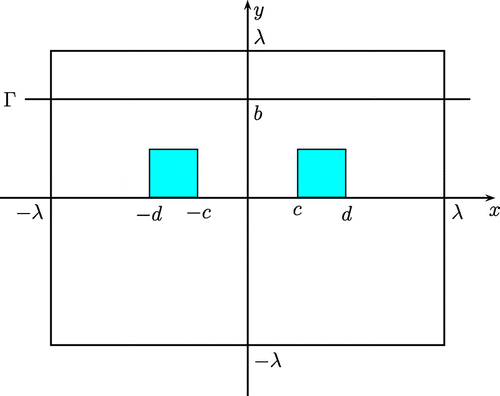
in the lower one. Two scatterers are presented on the surface of the substrate, in the domain
and
, respectively, where
, as is shown in Figure . The measurements of scattering field
are collected on the segment
. Here, we set
. And the measurements data are perturbed by a noise level
, i.e.
where rand gives uniformly distributed numbers in
. Thus,
Note that though we may set in some experiments, it does not mean that there is no noise, but that the machine precision plays the role of noise up to
which is not negligible in severely ill-posed problems.
Example 1
In this example, we mainly show how to choose the truncated number depending on the noise level
, and investigate the influence of the measurements height
. In this example, we set
and use scattering data by incident angles from
to
, and do several experiments to reconstruct the scatterer by scattering field from
and
, with the scatterers being apart by
, respectively.
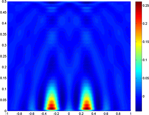
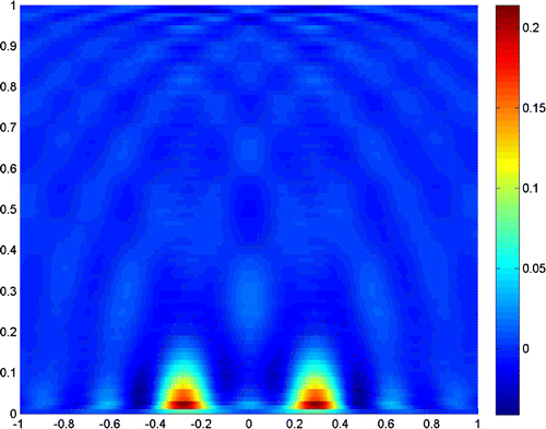
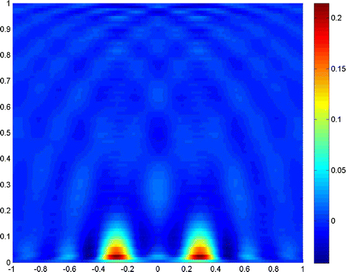
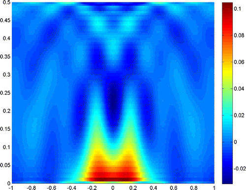
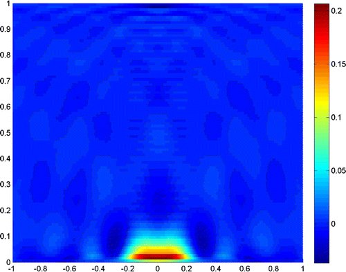
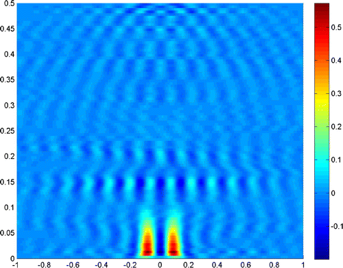
Figures – show where the two scatterers lie apart by , and the scattering field is detected on the segment
with
. Figures and show the results when
, and taking the truncated number
and
, respectively. It is readily seen that a truncated number should be small when noise level is low.
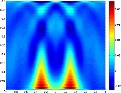
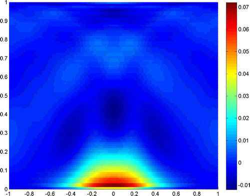
Next, we turn to the examples when the noise level increases. Figures and show the reconstruction result when the noise level is , and the truncated numbers are
and
, respectively.
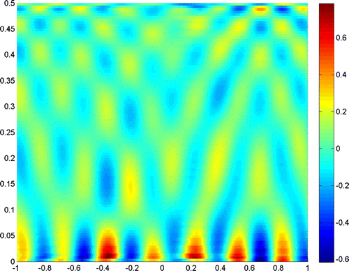
Figures and show the reconstruction results when the noise level is , and the truncated numbers are
and
, respectively. It is clear in Figure that the noise fails the reconstruction of the scatterer, but an appropriate truncated number in Figure retrieves the resolution.
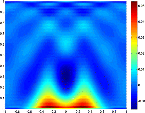
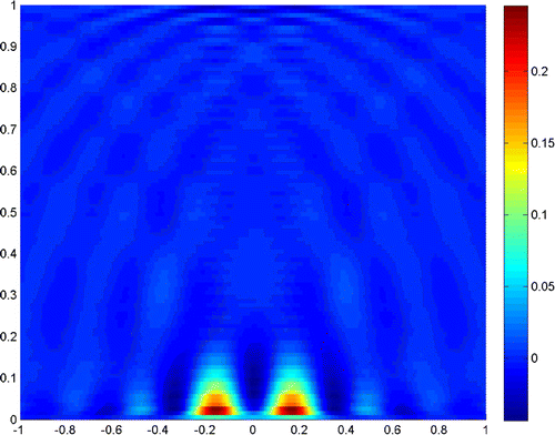
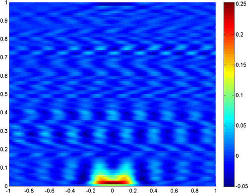
Now we continue the experiments when , with all the other data the same as before. Figures – show
,
and
, respectively. Compared to those when
, the reconstructions seem to be poor, but they can also give an acceptable resolution.
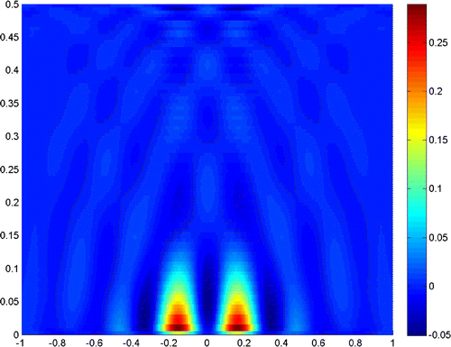
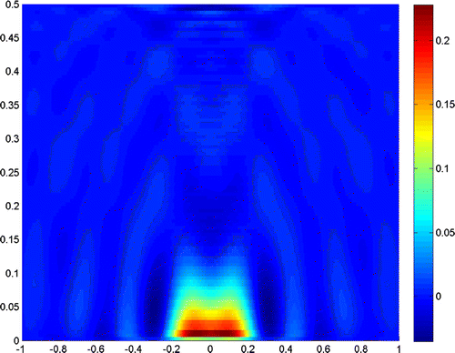
Next, we reduce the distance between the two scatterers to . Figures and show the results when noise levels are
and
, with measurements height
. Figures and show the results when noise levels are
and
, with measurements height
.
In the end of this example, when the distance between the two scatterers is reduced to , the reconstruction results only show the relative position of the scatterers but unable to clearly distinguish them, as is shown in Figures and .
Example 2
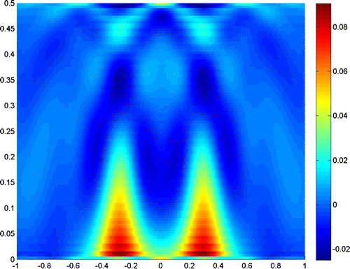
In this example, we show how the index of fraction in the lower half-space influences the reconstruction. Here, the distance between the two scatters is still
, which cannot distinguish the scatterers in the previous example. But when we set
instead of 1.2, the reconstruction is much better. The results are shown in Figures and , with measurements height
and
, respectively. Especially, when the measurements height is
, the two scatters can be distinguished clearly.
Example 3
In this example, we show how the incident angle influences the reconstruction. Here, we use all the parameters in Example 2 when the measurements height is . The critical angle when
becomes evanescent wave is
. So, we test the reconstruction when the incident angle varies between
in Figure , and when the incident angle varies between
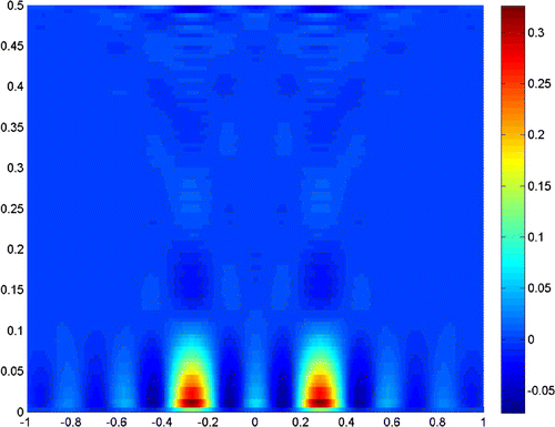
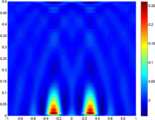
in Figure . The results tell us that fewer incident angles make the reconstruction poorer, but if we only use the evanescent waves, the results would also be acceptable.
The experiments show that the close measurements can lead to better resolution, and the truncated number plays a very important role in the reconstruction. In practice, we can get a good resolution when the truncated number is chosen close to the noise level. Besides, the larger refraction index of the lower half-space can improve the resolution of the reconstruction. More incident angles make the reconstruction better, but if we only use the evanescent waves, the results would also be acceptable for small scatterers. So, we can conclude that the evanescent waves play a very important role in near-field optics. But the exponentially ill-posedness generated by evanescent waves should be handled carefully by special regularization method, for example, the truncated SVD combined with moment method in this paper.
5 Conclusion
The inverse scattering problem in two-layered background is common and important in near-field optics. Based on the model of PSTM, we give an error bound of the inverse problem. We discuss inverse linear problem in detail and give the moment method with truncated SVD to handle the severely ill-posed problem with noisy data. Numerical experiments show that the method can give a resolution much better than .
There are two important future directions of the present study. The first concerns the more complicated three-dimensional model, where the three-dimensional Fredholm integral equation of the first kind should be solved. Another research direction is concerned with a finer error estimate of the Born approximation theoretically in our model.
Acknowledgments
The authors would like to thank the referees for their careful reading and valuable comments which led to improvement of the quality of our manuscript.
Notes
1 The research was supported by the National Natural Science Foundation of China (NSFC) [grant number 10971083], [grant number 11371172].
References
- Carney PS, Schotland JC. Near-field tomography. Inside Out: Inverse Prob. Appl. 2003;47:133–168.
- Carney PS, Schotland JC. Inverse scattering for near-field microscopy. Appl. Phys. Lett. 2000;77:2798–2800.
- Carney PS, Schotland JC. Three-dimensional total internal reflection microscopy. Opt. Lett. 2001;26:1072–1074.
- Carney PS, Schotland JC. Theory of total-internal-reflection tomography. J. Opt. Soc. Am. A. 2003;20:542–547.
- Carney PS, Schotland JC. Determination of three-dimensional structure in photon scanning tunnelling microscopy. J. Opt. A: Pure Appl. Opt. 2002;4:S140.
- Courjon D, Sarayeddine K, Spajer M. Scanning tunneling optical microscopy. Opt. Commun. 1989;71:23–28.
- Bao G, Li P. Inverse medium scattering for the Helmholtz equation at fixed frequency. Inverse Prob. 2005;21:1621–1641.
- Bao G, Li P. Inverse medium scattering problems in near-field optics. Int. J. Comput. Math. 2007;25:252–265.
- Markel VA, Mital V, Schotland JC. Inverse problem in optical diffusion tomography. iii. inversion formulas and singular-value decomposition. J. Opt. Soc. Am. A. 2003;20:890–902.
- Schotland JC, Markel VA. Inverse scattering with diffusing waves. J. Opt. Soc. Am. A. 2001;18:2767–2777.
- Moskow S, Schotland JC. Convergence and stability of the inverse scattering series for diffuse waves. Inverse Prob. 2008;24:065005, 16.
- Akduman I, Alkumru A. A generalized art algorithm for inverse scattering problems related to buried cylindrical bodies. Inverse Prob. 1999;11:1125–1135.
- Idemen M, Akduman I. Two-dimensional inverse scattering problems connected with bodies buried in a slab. Inverse Prob. 1999;6:749–766.
- Xu Y. Radiation condition and scattering problem for time-harmonic acoustic waves in a stratified medium with a nonstratified inhomogeneity. IMA J. Appl. Math. 1995;54:9–29.
- Li P. Coupling of finite element and boundary integral methods for electromagnetic scattering in a two-layered medium. J. Comput. Phys. 2010;229:481–497.
- Bao G, Chen Y, Ma F. Regularity and stability for the scattering map of a linearized inverse medium problem. J. Math. Anal. Appl. 2000;247:255–271.
- Arridge S, Moskow S, Schotland JC. Inverse Born series for the Calderon problem. Inverse Prob. 2012;28: 035003, 16.
- Epstein CL, Schotland J. The bad truth about laplace’s transform. SIAM Rev. 2008;50:504–520.
- Thamban Nair M, Pereverzev SV. Regularized collocation method for fredholm integral equations of the first kind. J. Complexity. 2007;23:454–467.
- Kirsch A. An introduction to the mathematical theory of inverse problems. Vol. 120, Applied Mathematical Sciences. New York (NY): Springer-Verlag; 1996.

![Figure 22. θ∈[-π/2,-θcr]∪[θcr,π/2],2c=λ/8, σ=0, Λ=10-6.](/cms/asset/3cdc6b9f-8549-4089-9fc2-a4cd72e9cc03/gipe_a_890611_f0022_oc.gif)
![Figure 23. θ∈[-θcr,θcr], 2c=λ/8, σ=0, Λ=10-6.](/cms/asset/11cf16a8-e2dc-4de0-99a3-c5faf912e9d5/gipe_a_890611_f0023_oc.gif)