
 ?Mathematical formulae have been encoded as MathML and are displayed in this HTML version using MathJax in order to improve their display. Uncheck the box to turn MathJax off. This feature requires Javascript. Click on a formula to zoom.
Abstract
An improved artificial bee colony algorithm (I-ABC) is proposed for crack identification in beam structures. ABC is a heuristic algorithm and swarm technique with simple structure, which is easy to implement but with slow convergence rate. In the I-ABC, the differential evolution (DE) mechanism is introduced to employed bee phase, roulette selection strategy is replaced by tournament selection strategy and a new formula is used to simulate onlooker bee’s behaviour. A discrete open crack is used for vibration analysis of the cracked beam and only the changes in the first few natural frequencies are utilized to establish the objective function of the optimization problem for crack identification. A numerical simulation and an experimental work are studied to illustrate the efficiency of the proposed method. Studies show that the present techniques can produce more accurate damage identification results when compared with original ABC, DE algorithm, particle swarm optimization and genetic algorithm.
1. Introduction
Due to unforeseen conditions and circumstances, it is never possible to design and build a structure that is not liable of failure. Structural ageing, adverse environmental effects, etc. are examples affecting the safety and reliability of a structure. If the damage is not handled appropriately in time, it may cause immense physical destruction and enormous economic loss. Therefore, regular inspection and condition assessment of an engineering structure are necessary so that early detection of any defect can be made, and the safety reliability of the structure can be determined.
Detection of cracks is an important part of the damage identification. A number of studies have been published in the area of crack identification and various crack models have been developed. There are many literatures dealing with cracks as a rotational spring;[Citation1–3] the reduction in stiffness is related to the depth of the crack. Another simple way treats a crack in finite element model (FEM) as the reduction of elemental Young’s modulus.[Citation4] Sinha et al. [Citation5] proposed a simplified crack model involving the crack location and depth directly.
Most of the crack or damage identification problems are solved in the time domain and frequency domain. Cawley and Adams [Citation6] are among the first ones to identify damage in elastic structure using natural frequencies. Narkis [Citation7] obtained a close relationship between crack location and eigen-frequency changes for a cantilever beam in transverse vibration and longitudinal vibration. Pandey et al. [Citation8] applied mode shapes from undamaged and damaged states to identify multiple damage sites. Cattarius and Inman [Citation9] used the time histories of vibration response of the structure to identify cracks in smart structures. Shi and Law [Citation10] calculated the modal strain energy change before and after the occurrence of damage as an indicator to identify damage. Law and Lu [Citation11] suggested a method based on modal superposition and optimization technique to identify the crack. Chomette and Sinou [Citation12] adopted optimal control technique to solve crack identification.
From a mathematical view, such an identification problem can be regarded as a non-liner optimization problem, in which an objective function, for instance the error between the actual measured structural response and the analytic response of a model, is defined and the parameters of such models are determined by optimizing the objective function (usually to maximum or to minimum).[Citation13] While adopting the classical optimization method to solve damage identification problem, it usually needs the gradient information and good initial values.[Citation14] However, methodologies based on heuristic stochastic algorithms can overcome these shortages and the usages of the heuristic algorithms gain popularity, especially the artificial bee colony (ABC) algorithm. It is a kind of swarm intelligence technique, first proposed by Karaboga, which is used to settle some numerical optimization problems. This algorithm is motivated by the bee colony’s behaviour of seeking high-quality food resource and it is a stochastic algorithm with simple structure and good robustness. Karaboga and Basturk [Citation15] applied it to optimize multivariable functions and also compared their results with those calculated by generic algorithm (GA), particle swarm optimization (PSO) algorithm and so on. It is exhibited that the ABC algorithm has a better ability to get the global optimal solution. Other numerical comparisons also demonstrated that the performance of the ABC algorithm is competitive to that of other population-based heuristic algorithms with an advantage of employing fewer control parameters.[Citation16] As its application in the engineering field, Sonmez [Citation17] used the ABC algorithm together with a penalty function method to minimize the weight of truss structures. Omkar et al. [Citation18] adopted ABC algorithm to design composite structures from a multi-objective optimization procedure. Although the ABC algorithm has been noted to be very successful in many optimization problems, very few works in the field of damage identification have been reported. Sun and Betti [Citation19] used the ABC algorithm with a non-linear factor to enhance the balance of global and local searches to realize the structural identification using time domain response. Sun et al. [Citation20] also used the ABC algorithm combined with Nelder–Mead simplex method to detect damages in building models. It should be pointed out that the ABC algorithm also has the shortage of trapping in the local optimal similar to other swarm intelligence algorithms. In order to get a more powerful optimization technique, the algorithm has to undergo improvement.
The paper mainly focuses on crack identification problem using an improved ABC algorithm (I-ABC) based on an objective function established with the first few natural frequencies. The advantage of the proposed method lies in that only a few natural frequencies’ measurements are needed for crack identification. Satisfactory identified results can be obtained for multiple crack identification. The study is organized as follows. Section 2 describes the formulation of crack identification as an optimization problem. Section 3 presents several improvements made for the original ABC algorithm. Section 4 gives the identified results of numerical simulations and a further verification from an experimental work. It is shown that the crack(s) can be identified successfully even when the first few noise contaminated natural frequencies of the beam structures are used. In Section 5, we present the observations and the conclusions of this study.
2. Modelling crack in beam structure and objective function for crack identification
2.1. Modelling crack in beam structure
In the majority of the works which aimed at diagnosing the state of crack, the structure is considered to be affected by single element crack or crack at one location; only few studies assure the presence of two element cracks, while the case of crack at more than three locations or triple element cracks has almost been ignored. And in this study, we try to identify as many as three cracks in the beam structures. In this study, we assume that the cracks in different elements do not interact with each other and that all the elements of the structure may be potentially cracked.
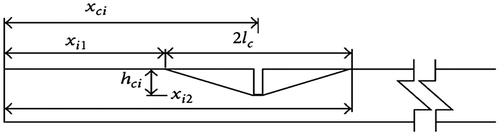
A crack in a structural element causes a reduction in the stiffness matrix of the element. Therefore, the stiffness matrix of a cracked element can be expressed as a function of the crack depth and crack location. In this study, a simplified form of the stiffness variation is used,[Citation5] in which the flexibility varies linearly from the un-cracked to cracked beam section, as shown in Figure . The variation in EI starts from an effective length, lc, on either side of the crack location, and at the position of highest flexibility, the stiffness is the second moment of area of the cracked section and is based on the crack depth. With the triangular reduction in stiffness, the crack depth and location are estimated directly.
Figure 1. Variation on flexural rigidity EI(x) adjacent to a crack.
The flexural rigidity close to the crack, EIe(x), is written as follows:
(1)
(1)
where E is Young’s modulus and and
are the moments of inertia of the intact and cracked cross sections, respectively. w and d denote the width and height of the undamaged beam, while dcj is the crack depth.
x is the location of the ith crack within the eth element. xi1 = xci − lc and xi2 = xci + lc are the positions where the reduction of the flexural rigidity commences and terminals, where lc is the effective length of the effect of the crack with .
The Euler–Bernoulli formulation was used to model the beam and only bending in a single plane is considered. A crack is assumed to be occurred within a beam element. The derivation of the reduced stiffness due to a single crack is outlined, assuming the ith crack at location xi within the eth element of beam.
The stiffness matrix of the eth element of the beam may be written as:
(2)
(2)
where is the element stiffness matrix for the eth element with no crack, and
is the reduction in the stiffness matrix due to the ith crack. This stiffness reduction,
, must be obtained in terms of the crack position and depth. The nodal degrees of freedom,
are ordered in the usual way. The stiffness matrix is obtained using the standard integration based on the variation in flexural rigidity as:
(3)
(3)
where the shape functions Nei(x) are those as a standard Euler–Bernoulli beam element. Similarly, the stiffness matrix can be constructed for other cracks. These element matrices are then assembled into the global stiffness matrix for the beam structure. Although cantilever beam structures are considered in the examples, this procedure can be extended into any other type of the beam members.
2.2. Objective function
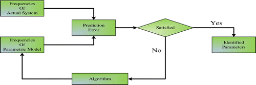
In general, crack identification based on an evolutionary algorithm is achieved by minimizing an objective function, which is defined in terms of the difference between the response parameters (natural frequency, etc.). These response parameters are identified either by testing or by the calculated data from a crack scenario. The (depth of crack) and xi (crack location) at xth location values of the members in the structure of concern have been taken as variables. Because no one knows the number and specific location of the cracks in advance, the total number of variables will be twice of the element number of the structure (supposing all the components of the structure are potentially cracked). The objective function that has been used is given as [Citation21]:
(4)
(4)
where denotes the frequencies of cracked structure, acquired either experimentally or by FEM and
represents calculated frequencies from numerical simulation using FEM. n is the number of frequencies used in calculation. It should be pointed out that the calculated natural frequencies are related with the crack parameters
. Figure presents the process of crack identification as an optimization problem.
Figure 2. Process of crack identification as an optimization problem.
3. Algorithm for crack identification
3.1. Introduction to the artificial bee algorithm
The artificial bee algorithm is motivated by the behaviour of bee forage. When foraging, the bees are classified as scout bees, employed bees and onlookers. The foraging process starts in a colony by scout bees, exploring food source by moving randomly. At the entrance of the hive is a zone called dance-floor, where they communicate with each other via waggle dance in order to recruit other bees to go to the food source. Their dances contain variety of information such as food quality, distance and so on. The onlookers watch many different dances and choose the best food source; then, they will become the employed bees, going to the best food source and exploiting the better source in the neighbourhood around the destination. If they find a better place, they will give up the primary best place. If the employed bees can’t find better source after exploiting the limited times, they will become the scout bees again, and continue to explore food randomly.
In the standard ABC algorithm, the number of employed bees is equal to the number of onlooker bees and equal to the number of food sources or solutions as well. And the nectar quality of food sources are related to fitness of a solution. This means that the fitness of the objective function is better, nectar quality is better and thus attracting more employed bees, which is a positive feedback mechanism in terms of optimization method.
The general structure of the algorithm is introduced as follows (Figure ).
Figure 3. Flow chart of ABC and I-ABC algorithms.
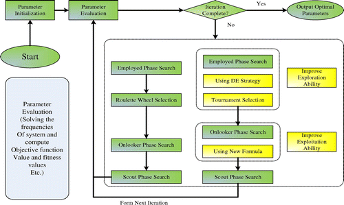
3.1.1. Initialization phase
Food source is expressed as Equation (5) in a random way
(5)
(5)
where m is the dimension, ui and li represent the upper bound and lower bound of the parameter xm,j.
3.1.2. Employed bees’ phase
Behaviour of the employed bee is to find a better food source in the neighbourhood of the food source (xm). It leaves the hive and finds the target point, and then begins the food exploitation. Equation (6) is used to simulate its behaviour
(6)
(6)
where xk is a food source, is a random number from [−1, 1] and i is a randomly chosen dimension. After producing a new candidate source, its profitability is calculated accordingly, and greedy selection is utilized between xm and Vm.
The fitness of each solution is calculated according to Equation (7).
(7)
(7)
3.1.3. Onlooker bees’ phase
The employed bees return home and share their food source information with the onlooker bees. They select the food source to exploit relying on the probability value pm
(8)
(8)
where SN denotes the number of employed bees; after selecting the food source, onlooker bees will fly there to exploit better food source. In the original ABC algorithm, the behaviour is also simulated by Equation (6), then fitness value is calculated applying the greedy selection to produce better food source.
3.1.4. Scout bees’ phase
If the food source couldn’t change after the limit number mentioned above, the food source will be abandoned and Equation (5) will be used to produce a new food source to replace the abandoned one. The limit parameter mentioned in scout phase can be calculated with Equation (9).[Citation16]
(9)
(9)
3.2. An I-ABC algorithm
3.2.1. Hybrid DE mechanism in employed bees’ phase
Meta-heuristic algorithms use different exploration and exploitation strategies for high-dimensional optimization problems. In order to improve the optimization ability of ABC, hybrid meta-heuristic algorithm is a new research field trend, which has attracted considerable attention in recent years.[Citation22] For example, Hu et al. [Citation23] introduced the search equation of the DE into the ABC to identify parameters of uncertain fractional-order chaotic system. Li and Yin [Citation24] utilized the hybrid DE/ABC algorithm to solve parameter estimation problem for the chaos as well. A novel hybrid swarm intelligence algorithm (IABAP) was developed by Shi et al. [Citation25] through using information communication between PSO and ABC and the exchange approach improved the performance of the algorithm. El-Abd [Citation26] proposed a hybrid approach referred to as ABC–short for Particle Swarm Optimization (SPSO), which is based on PSO and ABC, for continuous function optimization. Chun-Feng et al. [Citation27] proposed a novel ABC algorithm based on PSO search mechanism for global optimization. Such related studies all acquired more satisfied optimized results. Sharma and Pant introduced different operators into the ABC to balance its global and local search ability and acquire a better optimization result.[Citation28,29] Sharma and Pant integrated the ABC with PSO to solve multiple variable optimal problems and then obtained a more competitive outcome as well.[Citation30]
Therefore, we proposed a new hybrid procedure in the employed bee phase to promote the exploration ability in the early stage. DE [Citation31] is a simple but powerful population-based, direct search algorithm for global optimization problems. The basic treatment of DE is to create new candidate solutions by combining the parent individual and several other individuals of the same population, and the ‘greedy selection’ principle is also used to produce the new solution. The key idea behind DE is a scheme for generating trial parameter vector. If the trail vector gives a smaller value than a predetermined population member, the newly trail vector will be accepted and be compared in the following generation. As with the target vector selected process, different kinds of strategies have been proposed. In this study, DE/rand/1/bin mutation strategy is used, given as below:
(10)
(10)
ua,i is the new solution that will be crossed with the original solution xa,i; the cross regular is defined below:(11)
(11)
CR denotes the crossover rate and crossover operator can find the global optimal region.[Citation24] To the beginning of executing the algorithm, global search ability needs to be emphasized to prevent trapping the local optimal; hence, the DE mutation mechanism is introduced to the employed bee phase.
3.2.2. Tournament selection strategy used in selection phase
Tournament selection strategy (TSS) is adopted instead of roulette wheel to reinforce the global search ability further. Using the TSS, that is, first make the two comparisons of the fitness of each solution, the bigger one will get one point, then finish comparison; each solution will acquire its total point am and such total points will be used to calculate the selection probability based on Equation (12).
(12)
(12)
where am denotes the total points of a solution , compared with the roulette wheel; this strategy ensures that all solutions have a finite probability of selection, so those solutions with big fitness values do not overwhelm the search strategy. Thus, the probability of entrapment in a local optimum is reduced and prematuring is avoided.
3.2.3. A new formula introduced in onlookers phase
In real honey bee colony, an employed bee exploits the food source that it visited before, but an onlooker bee chooses a food source depending on the dances of employed bees. After reaching that region where it visits for the first time, the onlooker bee will examine food sources in the area and choose the best to exploit. Thus, the behaviour of onlooker bees should be different from the employed bees. However, in the original ABC algorithm, the formula used to simulate their actions is the same. To make the algorithm more similar with the real behaviour of collecting honey, a new formula [Citation32] is introduced to enhance onlooker bee’s exploitation ability, given as below:
(13)
(13)
where denotes the best solution among the neighbours of xm and itself. A similarity measure in terms of structure of solutions can be used to determine a neighbourhood for xm. At this point, in order to define an appropriate neighbourhood, different approaches could be used. In this study, Euclidean distance is introduced. As an instance, the neighbourhood of a solution
could be defined considering the mean Euclidean distance between xm and the rest of the solutions for the numerical optimization problems. Representing the Euclidean distance between xm and xj as
, the mean Euclidean distance for xm, mdm, is calculated by Equation (14).
(14)
(14)
If the Euclidean distance between xm and xj is less than the mean distance mdm, xj is defined as a neighbour of xm. With this expression, a new parameter r which refers to the ‘neighbourhood radius’ is added into the parameters of the onlooker bees’ phase. This parameter must be used as r ≥ 0. When r = 0, the neighbourhood of the solution xm will be only itself, turns to xm, the modified onlooker bee phase also turns to the standard phase. While the value of r increases, the neighbourhood of xm enlarges or its neighbourhood shrinks as the value of r decreases. On the other hand, if there are s solutions in its neighbour including itself,
can be written as:
(15)
(15)
The formula models the behaviour of onlooker bees more accurately and improves the performance of standard ABC in terms of local search ability, which is beneficial to the convergence rate. The improvements made aim at balancing the exploration and exploitation abilities of the algorithm.
4. Numerical simulation and experimental work
4.1. Numerical simulation
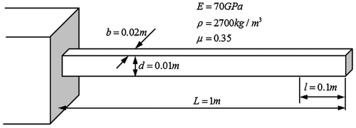
4.1.1. A cantilever beam
An aluminium cantilever beam is considered for the assessment of cracks by the DE, ABC and I-ABC, as is shown in Figure . The material properties of the beam are also marked in the figure. The colony size is 50 for all the algorithms, and the cross rate is 0.6 for the DE and I-ABC; meanwhile, the search radius is r = 5 for the I-ABC. To ensure fairness in comparison of the robustness of the examined algorithms, for each problem, the analysis is repeated 10 times with a different initial random seed. The averages are represented in a graphical form; the standard deviation and the worst results are listed in tables.
Figure 4. A cantilever beam.
4.1.1.1. Study case 1: identification of a single crack
A single crack in a cantilever beam is identified using the DE, ABC and I-ABC algorithms for comparison. The location of the crack is assumed to be at 650 mm from the fixed end with a depth 50% of the beam depth. In this case, the maximum iteration step is 200 and the first three natural frequencies are adopted to identify the crack parameters. Figure gives the comparison of the objective function value during the iteration process. One can find that the value from I-ABC is closer to zero than that from the DE and ABC algorithms, which means that the results acquired from I-ABC are most accurate in case 1. Figure (a) and (b) showcases the iteration process of the crack parameters. After experiencing about 100 cycles, the proposed algorithm nearly convergences to the assumed value. Figure and Table record the final identification results; the standard deviation of I-ABC is the smallest, which also means that the I-ABC yields a good estimation result with the smallest error. In addition, both DE and GA algorithms show false crack in other elements.
Figure 5. Iteration process of the objective function of case 1.
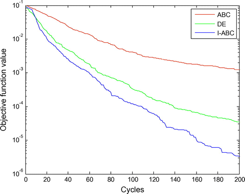
Figure 6. (a) Iteration process of the location parameter based on I-ABC of case 1. (b) Iteration process of the depth parameter based on I-ABC of case 1.
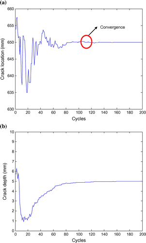
Figure 7. Identified results of case 1.
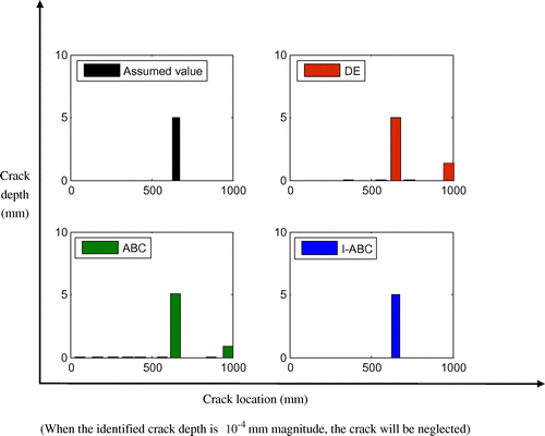
Table 1. Crack identified results for case 1 (unit: mm).
4.1.1.2. Study case 2: identification of double cracks
Two cracks in the cantilever beam are studied. In order to compare with the outcomes obtained from GA and PSO algorithms, the damage scenarios are set the same as those by Mohan et al. [Citation21], assuming that there are two cracks at 650 and 750 mm locations, with the depth 3 and 2 mm, respectively. In this case, the first six natural frequencies are adopted in the identification and the maximum iteration step is set as 800. Figure exhibits the typical iteration process of the objective function for this case. First, one can clearly find that the convergence rates of DE and ABC algorithms slow down with the crack numbers increasing; second, similar to the case 1, it is obviously observed that the I-ABC has a better convergence rate and better global search capacity and Figure gives more details about the crack parameters. Within 200 iterations, I-ABC converges to 650.0089, 750.0083 (locations of the two cracks), 2.9998 and 2.000 mm (crack depth of the two cracks), which are very close to the true crack parameters. Figure and Table present the final identified results. In summary, in the case of the double cracks identification, I-ABC can acquire the crack parameters more accurately compared with the other four algorithms.
Figure 8. Iteration process of the objective function of case 2.
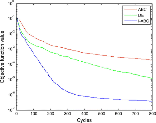
Figure 9. (a) Iteration process of the location parameter based on I-ABC of case 2. (b) Iteration process of the depth parameter based on I-ABC of case 2.
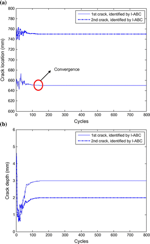
Figure 10. Identified results of case 2.
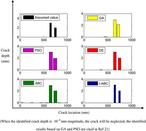
Table 2. Crack identified results for case 2 (unit: mm).
4.1.1.3. Study case 3: identification of triple cracks
In this study case, three cracks in the beam are identified. The scenario is also cited in [Citation21], i.e. assuming that there are three cracks at the 50, 250 and 350 mm locations with the same depth, 3 mm. In this scenario, the first six natural frequencies are adopted to calculate and the maximum iteration step is set to 1000 cycle. Figure gives the comparisons of the iteration process of the crack depth parameter based on DE, ABC and I-ABC algorithms. It can be seen that the ABC converges to the assumed value after almost 800 cycles and DE also convergences after nearly 500 cycles, while it only costs 200 iteration steps for I-ABC convergence. It is important to note that the more cracks to be identified, the more iteration steps for DE and ABC to converge; however, observing from cases 1 to 3, it seems that this factor has little influence for the I-ABC. Figure shows the final estimated results based on these algorithms. Table records the specific identified parameters of the cracks. As with the crack locations, GA predicts a slightly big error for the first crack (9.5 mm) and I-ABC obtains the corresponding error as 0.1107 mm, which is the smallest. Meanwhile, as with the crack depth, the I-ABC also performs well and yields good estimated results with the smallest standard deviations. The maximum identified error of the I-ABC is 0.0035 mm, occurring in the third crack, while for the GA, PSO, DE and ABC, the maximum errors are 0.2510, 0.0800, 0.0430 and 0.1024 mm, respectively, which can fully demonstrate the accuracy and high efficiency of the proposed approach.
Figure 11. Comparison on the iteration process for depth parameter based on DE, ABC and I-ABC algorithms.
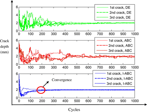
Figure 12. Identified results of case 3.
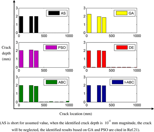
Table 3. Crack identified results for case 3 (unit: mm).
4.1.1.4. Study case 4: damage identification using noisy frequency data
In real measurements of natural frequency in structures, there can be a possibility of errors due to modelling error or measurement noise. In order to account for these errors in the measurements, normally distributed random noise is added to the simulated frequency data with zero mean and a variance of 1. The noisy natural frequency can be obtained by the following equation:
(16)
(16)
where is ith measured natural frequency with noise, while fi is the counterpart without noise. τi is the noise level and it is commonly believed that the measurement error of frequency is about 1%.[Citation33] Therefore, the considered noise in frequency measurement may be justified with the available knowledge in open literature. Hence, in order to simulate the experimental responses in a realistic way, 1% random noise is added to the analytic natural frequency. In order to compare with case 1, the parameters’ setting remains the same. Figure presents the final results; it can been seen that there appears a crack in the 10th element (un-cracked element) when the ABC algorithm is implemented; the DE also predicts two cracks in the un-cracked elements; however, the I-ABC can orientate the crack without error. The identified results are listed in Table . It is obviously seen that I-ABC algorithm yields better results (The maximum errors are 2.8981 and 0.2667 mm, respectively), compared with the DE (8.9339 mm for location and 0.5667 mm for depth) and ABC (7.2067 mm for location and 0.3442 mm for depth). Further, the standard deviation of the I-ABC is still the smallest, which reflects that the I-ABC seems relatively insensitive to artificial measurement noise.
Figure 13. Identified results of case 4.
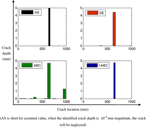
Table 4. Crack identified results for case 4 (unit: mm).
4.2. Experimental work
4.2.1. A fixed–fixed beam
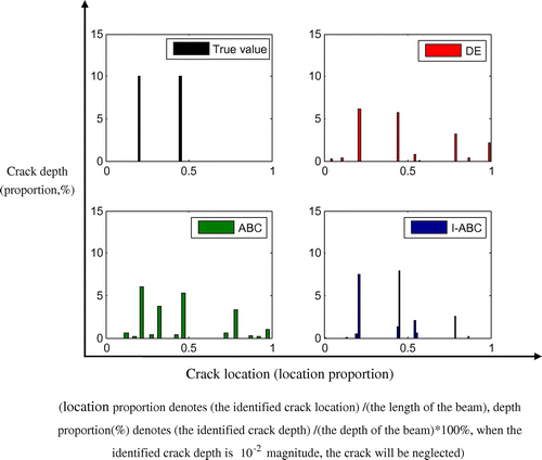
In this section, the experimental beam conducted by Khiem and Toan [Citation34] is used to examine the proposed techniques further. Geometric parameters of the beam are: l = 104 cm, b = 2 cm, h = 0.9 cm, ρ = 7855 kg m−3, E = 2 × 10¹¹ N m−2, as is shown in Figure . In the FEM of the beam, it is discretized into 20 Euler–Bernoulli beam elements (Figure ). The first six natural frequencies of the intact and the cracked beams are listed in Table along with those from the FEM. One can find that the difference in the natural frequency between the calculated and measured ones is very small, which shows the FEM is accurate enough for identification. In the experimental case, the first six natural frequencies of the damaged calmed beam is adopted to solve double cracks’ identification’. Table and Figure present the final identified results. One can find that for this case, the identified results from I-ABC are closer to the true crack parameters, with smaller standard deviations, compared with DE and ABC algorithms.
Figure 14. Experimental set-up for modal test of a fixed–fixed beam.[Citation25]
![Figure 14. Experimental set-up for modal test of a fixed–fixed beam.[Citation25]](/cms/asset/1507008b-0edc-4132-baa6-a737f00a248b/gipe_a_1160391_f0014_oc.gif)
Table 5. Calculated and measured natural frequencies of the test beam (unit: Hz).
Table 6. Crack identified results for case 5.
Figure 15. Identified results of case 5.
5. Conclusions
Crack identification based on an I-ABC algorithm using natural frequencies is investigated in this study. In the I-ABC, the DE mechanism is introduced to employed bees’ phase, roulette selection strategy is replaced by tournament selection strategy and a new formula is introduced to simulate onlooker bee’s behaviour to improve the convergence rate of the algorithm. Some conclusion can be drawn as follows:
| • | The I-ABC algorithm has proven to be very efficient for crack parameter identification: it converges relatively quickly, it is robust and yields small deviations of parameter estimation in each independent run. | ||||
| • | ABC and DE algorithms’ convergence rates may be affected a lot with the identified crack number’s increase, while it seems that this factor has little influence on the I-ABC. | ||||
| • | All the algorithms considered in this study yield good estimation results with small errors for noise-free cases. The I-ABC, however, performs more satisfactorily than others when dealing with the noisy frequency data. | ||||
| • | For the experimental work, the I-ABC still can acquire a more accurate result, compared with DE and ABC algorithms. Although there appear two locating errors in the about symmetric position, this is because the fixed–fixed beam is a symmetric structure, and only the first few natural frequencies are used to identify the crack(s), while lack of the mode shape. | ||||
Funding
This work was supported by the National Natural Science Foundation of China [grant number 11172333], [grant number 11272361]; Doctoral Program Foundation of Ministry of Education of China [grant number 20130171110039]; Guangdong Province Natural Science Foundation [2015A030313126]; and Guangdong Province Science and Technology Program [grant number 2014A020218004].
Disclosure statement
No potential conflict of interest was reported by the authors.
References
- Adams RD, Cawley P, Pye CJ, et al. A vibration technique for non‐destructively assessing the integrity of structures. J. Mech. Eng. Sci. 1978;20:93–100.10.1243/JMES_JOUR_1978_020_016_02
- Cheng SM, Swamidas ASJ, Wu XJ, et al. Vibrational response of a beam with a breathing crack. J. Sound Vib. 1999;225:201–208.10.1006/jsvi.1999.2275
- Sayyad FB, Bimlesh K. Theoretical and experimental study for identification of crack in cantilever beam by measurement of natural frequencies. J. Vib. Control. 2010;17:1235–1240.
- Kang F, Li JJ, Xu Q. Damage detection based on improved particle swarm optimization using vibration data. Appl. Soft Comput. 2012;12:2329–2335.10.1016/j.asoc.2012.03.050
- Sinha JK, Friswell MI, Edwards S. Simplified models for the location of cracks in beam structures using measured vibration data. J. Sound Vib. 2002;251:13–38.10.1006/jsvi.2001.3978
- Cawley P, Adams RD. The location of defects in structures from measurements of natural frequencies. J. Strain Anal. Eng. Des. 1979;14:49–57.10.1243/03093247V142049
- Narkis Y. Identification of crack location in vibrating simply supported beams. J. Sound Vib. 1994;172:549–558.10.1006/jsvi.1994.1195
- Pandey AK, Biswas M, Samman MM. Damage detection from changes in curvature mode shapes. J. Sound Vib. 1991;145:321–332.10.1016/0022-460X(91)90595-B
- Cattarius J, Inman DJ. Time domain analysis for damage detection in smart structures. Mech. Syst. Signal Process. 1997;11:409–423.10.1006/mssp.1996.0086
- Shi ZY, Law SS. Structural damage detection from modal strain energy change. J. Eng. Mech. 2002;126:1216–1223.
- Law SS, Lu ZR. Crack identification in beam from dynamic responses. J. Sound Vib. 2005;285:967–987.10.1016/j.jsv.2004.09.036
- Chomette B, Sinou JJ. Crack detection based on optimal control. J. Vib. Control. 2014;18:1737–1749.
- Franco G, Betti R, Lus H. Identification of structural systems using an evolutionary strategy. J. Eng. Mech. 2004;130:1125–1139.10.1061/(ASCE)0733-9399(2004)130:10(1125)
- Lu ZR, Law SS. Features of dynamic response sensitivity and its application in damage detection. J. Sound Vib. 2007;303:305–329.10.1016/j.jsv.2007.01.021
- Karaboga D, Basturk B. A powerful and efficient algorithm for numerical function optimization: artificial bee colony (ABC) algorithm. J. Global Optim. 2007;39:459–471.10.1007/s10898-007-9149-x
- Karaboga D, Basturk B. On the performance of artificial bee colony (ABC) algorithm. Appl. Soft Comput. 2008;8:687–697.10.1016/j.asoc.2007.05.007
- Sonmez M. Discrete optimum design of truss structures using artificial bee colony algorithm. Struct. Multidiscip. Optim. 2011;43:85–97.10.1007/s00158-010-0551-5
- Omkar SN, Senthilnath J, Khandelwal R. Artificial bee colony (ABC) for multi-objective design optimization of composite structures. Appl. Soft Comput. 2011;11:489–499.
- Sun H, Betti R. Simultaneous identification of structural parameters and dynamic input with incomplete output-only measurements. Struct. Control Health Monit. 2014;21:868–889.10.1002/stc.v21.6
- Sun H, Luş H, Betti R. Identification of structural models using a modified artificial bee colony algorithm. Comput. Struct. 2013;116:59–74.10.1016/j.compstruc.2012.10.017
- Mohan SC, Yadav A, Maiti DK, et al. A comparative study on crack identification of structures from the changes in natural frequencies using GA and PSO. Eng. Comput. 2014;7:1514–1531.
- Li ZY, Wang WY, Yan YY, et al. PS-ABC: a hybrid algorithm based on particle swarm and artificial bee colony for high-dimensional optimization problems. Expert Syst. Appl. 2015;42:8881–8895.10.1016/j.eswa.2015.07.043
- Hu W, Yu YG, Zhang S. A hybrid artificial bee colony algorithm for parameter identification of uncertain fractional-order chaotic systems. Nonlinear Dyn. 2015;82:1441–1456.10.1007/s11071-015-2251-6
- Li XT, Yin MH. Parameter estimation for chaotic systems by hybrid differential evolution algorithm and artificial bee colony algorithm. Nonlinear Dyn. 2014;77:61–71.10.1007/s11071-014-1273-9
- Shi X, Li Y, Li H, et al. An integrated algorithm based on artificial bee colony and particle swarm optimization. In: Proceedings of the 6th International Conference on Natural Computation. ICNC 2010; Yantai, Shandong, China; 2010 August 10–12; p. 2586–2590.
- El-Abd M. A hybrid ABC-SPSO algorithm for continuous function optimization. In: Proceedings of the IEEE Symposium on Swarm Intelligence (SIS); Paris; 2011; p. 1–6.
- Chun-Feng W, Kui L, Pei-Ping S. Hybrid artificial bee colony algorithm and particle swarm search for global optimization. Math. Prob. Eng. 2014: 8 pages. Article ID 832949.
- Sharma TK, Pant M. Differential operators embedded artificial bee colony algorithm. Int. J. Appl. Evol. Comput. 2011;2:1–14.
- Sharma TK, Pant M. Mixed DE-ABC algorithms for global optimization problems. Int. J. Artif. Intell. Knowl. Discovery. 2011;1:58–63.
- Sharma TK, Pant M. PSO embedded artificial bee colony algorithm. Int. J. Appl. Eng. Res. 2011;6:2243–2247.
- Storn R, Price K. Differential evolution – a simple and efficient heuristic for global optimization over continuous space. J. Global Optim. 1997;11:341–359.10.1023/A:1008202821328
- Karaboga D, Gorkemli B. A quick artificial bee colony (qABC) algorithm and its performance on optimization problems. Appl. Soft Comput. 2014;23:227–238.10.1016/j.asoc.2014.06.035
- Hao H, Xia Y. Vibration-based damage detection of structures by genetic algorithm. J. Comput. Civ. Eng. 2002;16:222–229.10.1061/(ASCE)0887-3801(2002)16:3(222)
- Khiem NT, Toan LK. A novel method for crack detection in beam-like structures by measurements of natural frequencies. J. Sound Vib. 2014;333:4084–4103.10.1016/j.jsv.2014.04.031