 ?Mathematical formulae have been encoded as MathML and are displayed in this HTML version using MathJax in order to improve their display. Uncheck the box to turn MathJax off. This feature requires Javascript. Click on a formula to zoom.
Abstract
In this paper, we study the inverse scattering of tapered waves from sound soft surfaces or horizontally polarized electromagnetic waves from perfectly conducting surfaces. By the related Fréchet derivative with respect to a given surface of the solution of direct scattering problems, an efficient algorithm is proposed to reconstruct the parameters of unbounded rough surfaces from a set of scattered field measurements. Tapered wave is introduced to realize the asymptotic truncation for unbounded fractal rough surface. In order to improve the results of reconstruction, multi-angle and multi-frequency incidence strategy has been used. The numerical results show that the method yields satisfactory reconstructions for some rough surface profiles.
1. Introduction
Inverse scattering problems are of great interest because of their potential applications in biomedical imaging, non-destructive testing and diagnostics, remote sensing applications, applied geophysics and non-invasive subsurface monitoring. The inverse scattering of rough surface is such problem that the incident wave is given and the measurement data of scattering wave are assumed to be known, on the basis of which the characteristic information of the unbounded rough surfaces such as geometric parameters and physical properties can be confirmed and reconstructed. Parameters inversion of rough surface constitutes an important class of problems in inverse scattering theory due to the large range of applications such as microwave remote sensing, underwater acoustics and target recognition. In these problems, one tries to recover the multi-parameter of an unknown fractal rough surface from scattered field measurements in a certain domain. It is a simplification of ground (Surface models) imaging via ground-penetrating radar (GPR). In GPR systems, arrays of above-ground transmitters and receivers illuminate surfaces of interest and receive scattered data from the rough surface. The rough surface to be reconstructed can be either perfectly conducting or a dielectric interface separating two dielectric media.
The problem of parameter identification and shape reconstruction has attracted the attention of many scholars. Some investigations have been developed to solve the problems in recent years. For the periodic rough surfaces (such as grating), some scattering and inverse scattering problems have been studied (see, e.g. [Citation1–Citation5] and references therein). In [Citation6], the authors discuss the reconstruction of a fractal rough surface with periodic boundary conditions, a single-parameter (fractal dimension) is reconstructed directly by linear search method. For the locally rough surface, the integral equation method for scattering and inverse scattering problems has been considered (see, e.g. [Citation7,Citation8]). In reality, the ground is an unbounded randomly rough surface, which makes it more challenging to reconstruct its profile. Near-field imaging of one kind of unbounded rough surfaces is considered in [Citation9]. Several analytic and numerical techniques have been developed for studying electromagnetic scattering and inverse scattering from random rough surfaces without and with certain targets, respectively (see, e.g. [Citation10–Citation15]). Many works are based on the Kirchhoff approximation with the rough surface assumed to be locally planar (see, e.g. [Citation16–Citation18]), which accounts only for the single scattering and not the multiple scattering. The other methods such as the coupled integral equation method (see, e.g. [Citation19,Citation20]), the linear sampling method (see, e.g. [Citation21]) and the point source method (see, e.g. [Citation22]) have been proposed for solving the non-linear inverse problem and determining the profile of the rough surface.
In this paper, the rough surface is characterized by one-dimensional band-limited Weierstrass–Mandelbrot function, and it is subject to the Dirichlet (zero field) boundary condition. With fast and accurate solver for the direct scattering problem which we presented in [Citation23], the optimization algorithms for multi-parameters inversion and shape reconstruction of unbounded non-periodic rough surface are investigated. The reconstruction algorithm is based on merging a fast direct solver and a non-linear optimal technique. The goal is to minimize an objective function relating parameters of the rough surface to the scattered field data. Firstly, we introduced the related Fréchet derivative with respect to parameters of a given surface for the solution of direct scattering problems. It is a basis for the optimization algorithm. Secondly, we use BFGS method [Citation24] to solve the non-linear optimization problem. For each step, it needs to apply a direct solver several times for solving the direct problem and the Fréchet derivative of objective function. Finally, the multi-angle and multi-frequency incidence strategy has also been considered. By Abbe’s resolution formula, it is reasonable to expect the better results should be obtained when the multi-frequency data are used. Additionally, illuminating the unknown rough surface from more directions should make the surface easier to recover. The measurements of scattered field are generated by certain numerical method (such as the regularized conjugate gradient method (RCGM),[Citation23] and method of moments [Citation15]), and they are used to replace the real collected GPR-type data to test the reconstruction algorithm. Several key issues will be examined such as the reconstruction accuracy, the influence of measurement error, initial data and the surface roughness.
The organization of the paper is as follows: In Section 2, we describe the scattering problem of unbounded rough surface with tapered wave incidence and the boundary integral formalism. To solve the optimization problem for the parameters inversion of the function f from these measured data, the Fréchet derivative of the scattered field is introduced. The numerical solution of the integral equation is also briefly discussed. In Section 3, the numerical inversion method for reconstructing the rough surface is presented. The feasibility of the method is illustrated through some numerical examples, and the numerical results are discussed in Section 4. Finally, the concluding remarks are given in Section 5.
2. Scattering problem of fractal rough surfaces
2.1. Rough surface function and Scattering problem
The parameters inversion and shape reconstruction of the unbounded rough surface begin with assuming a mathematical model of the surface that can approximately define its height variation. The geometric shape of unbounded rough surfaces (such as sea surface and ground surface) are often represented by means of a deterministic function as well as a stochastic process (see, e.g. [Citation14,Citation25]). Since fractals hold in balance long-range order and short-range disorder, here the band-limited fractal function f is used to describe the rough surface(1)
(1)
where is the fundamental surface period,
is the fundamental surface wave number,
is the frequency scaling parameter,
is the root mean square height,
is the fractal dimension,
is the highest harmonic wave number,
is a normalization factor and
is the specified phases. For more details of the band-limited fractal function, we refer the interested reader to [Citation6,Citation26,Citation27].
We assume that the unbounded fractal rough surfaces are impenetrable and
is the propagation domain above f, which can be expressed as
For considering the scattering problem of unbounded rough surfaces, the Thorsos tapered wave is used as the incident field
(2)
(2)
which satisfies the non-homogeneous Helmholtz equation(3)
(3)
where(4)
(4)
and(5)
(5)
In fact, as
.
is the angle of incidence (it is the angle between the direction of propagation and the negative z axis), and g is the parameter that controls the tapering,
is the wave number,
is the wavelength of incident wave,
and
. The tapered wave is introduced by Thorsos in 1988 [Citation16], which has been well received in the electromagnetics community. In the process of numerical calculation, the rough surface must be truncated in a finite interval. This means that the surface current is forced to be zero outside the interval for plane wave incident. If there is an abrupt change of surface current from non-zero to zero, artificial reflection from the two endpoints will occur. Note that at
(or z is equal to a constant), the amplitude of the tapered incident field decreased exponentially for
. So it can be used to realize the asymptotic truncation.
The total field consists of the incident field
and the scattered field
:
(6)
(6)
where the scattered field satisfies the homogeneous Helmholtz equation
(7)
(7)
We describe the scattering model mathematically as follows (see, e.g. [Citation16,Citation23,Citation28,Citation29])(8)
(8)
For a sound soft (or perfectly conducting) surface, the total filed vanishes on the rough surface,
(9)
(9)
The scattering problem is not complete without a suitable radiation condition. Physically, such a condition ensures that the scattered field is propagating away from the surfaces while mathematically, it ensures uniqueness of the solution. A natural approach to obtain a radiation condition, often used in applications, is to consider the field only in the domain
and to compute its Fourier transform
with respect to the x variable. This leads to an ordinary differential equation
(10)
(10)
with some initial condition, e.g. for
. Selecting the outgoing of the two linearly independent solutions, we arrive at
(11)
(11)
Equation (Equation11(11)
(11) ) is often referred to as an angular spectrum representation. The formalism can easily be made mathematically rigorous if
. It is worth noting that the radiation conditions (Equation11
(11)
(11) ) is different from the classical Sommerfeld’s radiation conditions. The Sommerfeld’s radiation condition is not a valid characterization of outgoing waves for scattering problems at unbounded rough surfaces. A simple example is the scattering on a flat surface: for a downward propagating incident wave, the scattered field
is simply some reflected wave and hence satisfies Sommerfeld’s radiation condition only in the propagation direction. So the angular spectrum representation is proposed to replace the Sommerfeld’s radiation condition (see, e.g. [Citation30–Citation32]).
2.2. Boundary integral equations
The boundary integral equation (BIE) approach has been developed to handle the scattering problem (Equation8(8)
(8) ), (Equation9
(9)
(9) ) and (Equation11
(11)
(11) ). Using Green’s theorem and the angular spectrum representation radiation condition, we derived the BIE (Equation12
(12)
(12) ) in [Citation33]
(12)
(12)
where it is the fundamental solution to the Helmholtz equation in
,
is the unit normal vector pointing towards the inside of
from
, where
and
represent the unit vectors of x axis and z axis, respectively.
It is notable that most of the literature considers the approximation for the tapered wave rough surface scattering problem as follows:(13)
(13)
The derivation of BIEs for scattering by unbounded rough surface with plane wave incidence has been studied in detail by J.A. DeSanto and P.A. Martin in [Citation31,Citation32,Citation34]. They pointed out that the BIE (Equation13(13)
(13) ) is an approximate equation with tapered wave incidence (see [Citation31], Sec.VI.D). We consider the integral equation (Equation12
(12)
(12) ) directly. With Dirichlet boundary condition, the surface integral Equation (Equation12
(12)
(12) ) is converted to
(14)
(14)
where . It remains to discuss the discretization and solution of (Equation14
(14)
(14) ). For this, we assume the boundary
is parameterized, and it is truncated in an finite integration interval
(15)
(15)
where is the corresponding right-hand side. We discretize the integral equation by a collocation method, with N equispaced points corresponding to
on the boundary for
. We assign an unknown value
at each such point and enforce the integral equation pointwise at the same points. Because the integral is logarithmically singular, the small argument approximation of the Hankel function is employed (see, e.g. [Citation15]). The discretization would yield a dense matrix(
). The discrete linear systems can be expressed as
(16)
(16)
where . For solving the equations, one of the limitations is that the computational complexity grows dramatically as the size of the scattering surface increases. The RCGM with fast multipole acceleration which we proposed in [Citation23] is used to solve the problem.
3. Regularized conjugate gradient method
(Algorithm 3.1 in [Citation23])
| (1) | Input the noise level | ||||
| (2) | Input the initial guess | ||||
| (3) | Compute the received power by the rough surface | ||||
| (4) | Input | ||||
| (5) | do while ( | ||||
| (6) | if | ||||
| (7) | compute | ||||
| (8) | Set | ||||
3.1. The Fréchet derivative of the scattered field
Let denote the unknown parameter vector of the rough surface.
denotes a sufficiently small admissible perturbation of
which is a component of the vector
, and
. The corresponding solution of scattering problem is denoted as
in
, where
is a domain which is determined by
, this is
According to the above definition, we have
The direct scattering problem of rough surface can be formulated as the boundary value problem:(17)
(17)
where is the Fourier transform of
,
,
,
.
We formulate the problem as the operator forms. For a fixed incident field , define a scattering operator
(
) by
(18)
(18)
where , for
,
is the values of the scattered field
on the line
. In the following, we assume that the scattered field is continuously Fréchet differentiable with respect to parameter
. The Fréchet derivative is denoted as
. Then, we have
Lemma 2.1:
The Fréchet derivative satisfies the following equation:
Proof:
Let(19)
(19)
where I is the identity mapping. And define(20)
(20)
It follows from (Equation17(17)
(17) ) that
(21)
(21)
solving the derivative of (Equation21(21)
(21) ) about
and taking derivative values at
, we have
(22)
(22)
From (Equation21(21)
(21) ), which implies that
(23)
(23)
thus (Equation22(22)
(22) ) is simplified to
(24)
(24)
Since the operator A is a linear and continuous operator, we have(25)
(25)
that is(26)
(26)
The Lemma 2.1 is proved.
Lemma 2.2:
The Fréchet derivative satisfies the following boundary condition:
Proof:
Solving the derivative of the boundary condition of (Equation17(17)
(17) ) about
, we have
(27)
(27)
Hence, from (Equation27(27)
(27) ), we can get
(28)
(28)
The Lemma 2.2 is proved.
Lemma 2.3:
The Fréchet derivative satisfies the following outgoing radiation condition:
where , and
is chosen such that the half-plane
and
.
Proof:
This lemma results from the asymptotic behaviour of the scattered field . Indeed, the scattered field
satisfies the angular spectrum representation condition as follows:
(29)
(29)
where is chosen such that the half-plane
and
.
Solving the derivative of (Equation29(29)
(29) ) with respect to parameter
and taking derivative values at
, we have
(30)
(30)
The Lemma 2.3 is proved.
According to the above lemmas, we get the following theorem.
Theorem 2.4:
The Fréchet derivative is the solution of the boundary value problem as follows:
(31)
(31)
where is chosen such that the half-plane
and
.
It is shown by Theorem 2.4 that the Fréchet derivative of operator can be characterized by a solution
of the boundary value problem (Equation31
(31)
(31) ).
Theorem 2.5:
The operator is Fréchet differentiable and its derivative with respect to parameter
is given by the solution of the boundary value problem (Equation31
(31)
(31) ), that is
(32)
(32)
4. Multi-parameter identification and shape reconstruction
In this section, we will discuss the inverse scattering problem and reconstruction algorithm. In the inverse problem, given the measured scattering field which is denoted by , we want to determine the unknown parameter vector
of fractal rough surface such that
(33)
(33)
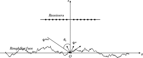
The geometry of the problem is shown in Figure Since represents the symbolic relation between the parameters
and the scattered fields, it involves coupled integral representations of fields described in Equations (Equation13
(13)
(13) ) and (Equation15
(15)
(15) ). The relationship between the rough surface and the scattered filed is non-linear if single scattering is not assumed. In fact, the inversion problem can be written as an optimization problem. That is, find
such that
(34)
(34)
where means certain kind of norm.
Figure 1. A schematic of the rough surface inverse scattering problem with the tapered wave incidence.
In the following, a numerical method for the parameters inversion of the rough surface from the measured data is described. For the illumination of the rough surface by M-prescribed incident fields (
), we can obtain the corresponding measurements of scattered fields at nth observation points
, and they are denoted by
. Based on the measurements
, we wish to evaluate the objective function
by matching the measurements with the numerical simulations for the trial distributions:
(35)
(35)
where represent the scattered fields which are dependent on
. The dimension of vector
is determined by the assumed mathematical model of the surface profile.
To solve the optimization problem (Equation35(35)
(35) ) for the parameters inversion of the rough surface function f by BFGS method, we need to consider the existence of the gradient
of the objective function
. From (Equation35
(35)
(35) ) and Theorem 2.5, the following theorem can be proved.
Theorem 3.1:
The gradient of the objective function
exists.
Based on the above analysis, the reconstruction algorithm is summarized as follows:
Step 1. Choose an initial guess of
, an accuracy
and a symmetric positive definite matrix
. Set
.
Step 2. Solve the boundary value problem (Equation31
(31)
(31) ) by the integral equation method to get the numerical solutions
. If
, stop the algorithm. Otherwise, compute the direction
by
Step 3. Find an acceptable
such that
Step 4. Set
, then compute
Step 5. Let
, and repeat Steps 2–4.
5. Numerical results
In this section, we illustrate the performance of the inversion algorithm. In the following numerical examples, we consider two cases of reconstruction, respectively. One is the reconstruction with a single incident wave; the other one is the reconstruction with multi-angle and multi-frequency incident waves.
5.1. Single incidence reconstruction
We consider the inverse scattering problem for the fractal rough surface which is generated by the surface height function f(x), where the parameters
, and the other parameters
, K are given for each numerical experiment below. The surface is truncated in a finite integration interval
. For tapered wave incidence, we set the wavelength
and the incidence angle
. To avoid the edge effect and assure the computational precision, we set the tapered factor g = L / 2 as in [Citation29]. For solving the direct problem, the rough surface is divided into N segments (
), where
is the space interval. The scattered field measurements
are obtained at the angles
,
and
. They are applied to replace the real collected GPR-type data to test the reconstruction algorithm. Let
,
and
denote the inversion results of
respectively,
denote the number of iterations,
denote the maximum error between the reconstructed surface
and the original real one f(x), i.e.
.
For two parameters inversion, set and
. We show the inversion results of
and
under different conditions in Tables –. As we can see clearly from the Table , although for these examples we all choose the initial data as
, our approach can reconstruct the parameters of the rough surface very well.
Table 1. The two-parameter inversion results of the fractal rough surface.
In fact, there are errors for the measurements. To test the influence of measurement error, some random noises are added on the measurement information. For the relative noise level , the measurements are constructed in the following way:
(36)
(36)
where is a random vector, the element of the vector
normally distributed,
. For two Matrices, A and B, of the same dimensions, the Hadamard product
is a matrix of the same dimensions, and
.
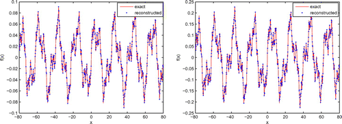
So we show the inversion results with the measurement data which bring 1% noise for different parameters of the rough surface in Table . We can see that the numerical results are close to the theoretical values. Meanwhile, the results of shape reconstruction of the fractal rough surfaces are also given in Figures and .
Table 2. The two-parameter inversion results of the fractal rough surface with 1% noise level.
In Tables –, we analyse the influence of some parameters for the algorithm as mentioned above, such as the error of the measurements, the initial guesses and the survey positions. The comparisons of the different errors of the measurement data for the numerical results are shown in Table . The maximum error is less than when the noise level does not exceed 5%. Based on the above comparisons, we can see that the results are satisfactory.
Table 3. The two-parameter inversion results of the fractal rough surface with 1–5% noise level.
In Table , we can see the influence of initial guesses on the numerical results. It is found that when the initial guesses are not far from the real one, the inversion results are in fairly good agreement with the theoretical values of these numerical examples. In this paper, we choose some initial parameters to test the algorithm. In practical problems, the better initial guesses could be obtained by some analytical approximation methods or some direct inversion methods (see, e.g. [Citation16,Citation17]). From Table , we can see that the survey position has little influence on the inversion results. The calculation results are in fairly good agreement with different survey positions for all these numerical examples.
These parameters of the rough surface have a very complex impact on the scattering field, which together determine the distribution of scattered field. From the inversion results which are shown in the Tables –, we can see that some information of the rough surface, such as parameters , can be retrieved from the measurements very well, and the parameters such as the error of the measurements, the initial data and the survey position have different effects on the simulation results. The numerical results show that the algorithm yields satisfactory reconstructions for some rough surface profiles.
Table 4. The two-parameter inversion results of the fractal rough surface with different initial values.
Table 5. The two-parameter inversion results of the fractal rough surface with different survey positions.
For three parameters inversion, we still let , and the initial guess
,
. Note that the estimated parameters are used as initial guesses to start the algorithm again if the error value Max
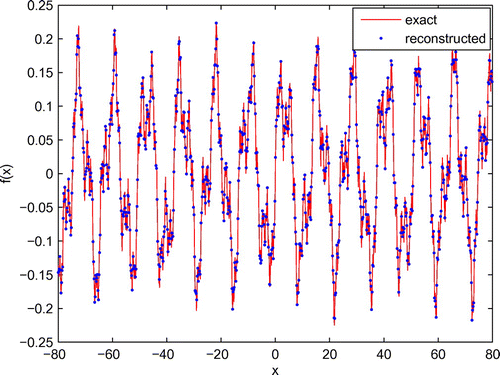
after more than 30 iterations. In Table , we found that despite the relatively large number of iterations used, the approach can reconstruct the parameters of the rough surface as well. The surface profile of the fractal rough surface is also reconstructed in Figure .
Table 6. The three-parameter inversion results of the fractal rough surface.
5.2. Multi-angle and multi-frequency reconstruction
We now move to consider the incidence of multi-angle and multi-frequency. Firstly, we consider the multiple incidence strategy with a single frequency. For one incident angle, we use the scattered field measurements at all receivers simultaneously and then change the objective function after each determination of the parameters of rough surfaces corresponding to each incident angle. Secondly, we consider the multi-frequency strategy with a single incident angle. Similar to the multiple incidence strategy with the single frequency, for one fixed frequency, we use the scattered field measurements at all receivers simultaneously and then change the objective function after each determination of the parameters of rough surfaces corresponding to each frequency. To improve the results of reconstruction, the combined approach can be implemented as the multi-frequency strategy followed by multiple incidence strategy (which is implemented by the multiple incidence strategy for each frequency from low to high). Conversely, it also can be implemented as the multiple incidence strategy followed by multi- frequency strategy (which is implemented the multiple frequency strategy for each incident angle from small to big).
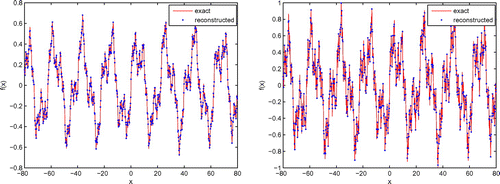
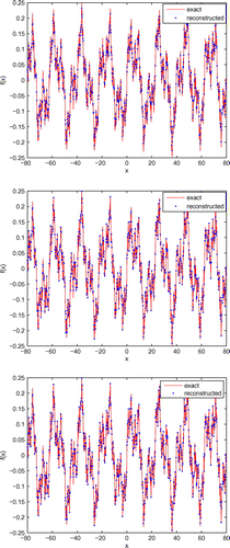
Figure 5. Reconstruct the surface for with 1% noise by single-incidence (The top), multiple-angle incidence (The middle) and multiple-frequency incidence (The bottom).
Let the incident angles =
,
and
, respectively, and set
,
. At
=
, the inversion algorithm starts with the initial guess
for certain inversion iterations. The above inversion results are then used as initial values in the inversion algorithm at
for certain inversion iterations. This process is repeated at the incident angle
. The numerical inversion results are listed in the Table to show a comparison between the inversion results with multiple incidence (M-A) and single incidence (S-I) at a fixed frequency (
), where the incident angle of S-I is
. All these results are obtained for the same objective function. The multiple incidence strategy need only five inversion iterations at each incident angle. It can achieve the same precision with fewer iterations. We can see that the multiple incidence strategy shows a better result in the parameters reconstruction.
Table 7. The two-parameter inversion results with multiple incidence and single incidence at a fixed frequency.
In Table , we show the parameters inversion results as with different wavelengths
and 0.5, respectively, for incident angle
. We start the algorithm at
with the initial guess of the parameters
for certain inversion iterations. The inversion results are then used as the initial values in the inversion algorithm at
for certain inversion iterations. This process is repeated at the wavelength
, where M-F represent the multi-frequency incidence. By the reconstructing parameters
and
, we also show the inversion results of the rough surface for different cases in Figure . Based on the numerical results, we can see that the results of reconstruction can be improved with multi-frequency strategy. It requires fewer iterations to achieve the same precision.
Table 8. The two-parameter inversion results of the fractal rough surface with multiple frequency incidence.
Table 9. The three-parameter inversion results of the fractal rough surface.
For three parameters inversion, multiple incident angles and multiple frequency can be used simultaneously. The initial guesses ,
and
are used to start the algorithm. Note that the estimated parameters are used as initial guess to start the algorithm again for other incident angles or frequencies if the error value Max
after more than 30 iterations. In Table , we only used one wave length
and two incident angles
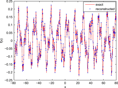
simultaneously; we found that despite the relatively large number of iterations used, the approach can reconstruct the parameters of the rough surface as well. The surface profile of the fractal rough surface is also given in Figure .
6. Summary and conclusions
We present an inversion algorithm to reconstruct the parameters of an unbounded fractal rough surfaces with tapered wave incidence. Given the scattered field measurements, we reconstruct the parameters of unbounded rough surfaces. First, the parameters inversion problem is viewed as an optimization problem, and the unknown parameters of the rough surfaces are estimated by minimizing an objective function. By the related Fréchet derivative with respect to the surface parameters of the solution of direct scattering problems, an efficient reconstruction algorithm is proposed. Second, the influence of measurement error, initial data, survey position and different rough surfaces on the inversion results is studied. Finally, multiple incidence strategy is used to improve the conditioning of the reconstruction problem. The incidence strategy of multi-angle and multi-frequency can make us obtain better reconstruction results than single incidence with much less iterations. The numerical results show that the proposed algorithm is accurate, and the inversion results can be obtained with reasonable computing times.
Acknowledgements
The authors would like to thank the referees for their constructive comments and suggestions which helped improve the paper.
Additional information
Funding
Notes
No potential conflict of interest was reported by the authors.
References
- Bao G, Li P, Lv J. Numerical solution of an inverse diffraction grating problem from phaseless data. J. Opt. Soc. Am. A. 2013;30:293–299.
- Bao G, Bonnetier E. Optimal design of periodic diffractive structures. Appl. Math. Opt. 2001;43:103–116.
- Bao G, Huang K, Schmidt G. Optimal design of nonlinear diffraction gratings. J. Comput. Phys. 2003;184:106–121.
- Bao G, Cowsar L, Masters W. Mathematical modeling in optical science. Philadelphia: SIAM; 2001.
- Bao G, Li P, Wu H. A computational inverse diffraction grating problem. J. Opt. Soc. Am. A. 2012;29:394–399.
- Cai Z, Chen D, Lu S. Reconstruction of a fractal rough surface. Phys. D: Nonlinear Phenom. 2006;213:25–30.
- Ammari H, Bao G, Wood A. An integral equation method for the electromagnetic scattering from cavities. Math. Meth. Appl. Sci. 2000;23:1057–1072.
- Zhang HW, Zhang B. A novel integral equation for scattering by locally rough surfaces and application to the inverse problem. SIAM J. Appl. Math. 2013;73:1811–1829.
- Bao G, Li P. Near-field imaging of infinite rough surfaces. SIAM J. Appl. Math. 2013;73:2162–2187.
- Bahar E, El-Shenawee M. Enhanced backscatter from one dimensional random rough surfaces-stationary phase approximations to full wave solutions. J. Opt. Soc. Am. A. 1995;12:151–161.
- Colton D, Monk P. Target identification of coated objects. IEEE Trans. Antennas Propag. 2006;54:1232–1242.
- Fung K, Shah MR, Tjuatja S. Numerical simulations of scattering from three-dimensional randomly rough surfaces. IEEE Trans. Geosci. Remote Sens. 1994;32:986–994.
- Johnson JT, Tsang L, Shin RT, et al. Backscattering enhancement of electromagnetic waves from two-dimensional perfectly conducting random rough surfaces: a comparison of Monte Carlo simulations with experimental data. IEEE Trans. Antennas Propag. 1996;44:748–756.
- Tsang L, Chan CH, Pak K, et al. Monte Carlo simulations of large-scale composite random rough-surface scattering based on the banded-matrix iterative approach. J. Opt. Soc. Amer. 1994;11:691–696.
- Tsang L, Kong JA, Ding KH. Scattering of electromagnetic waves. Vol. 2, Numerical simulations. New York (NY): Wiley Interscience; 2001.
- Thorsos EI. The validity of the Kirchhoff approximation for rough surface scattering using a Gaussian roughness spectrum. J. Acoust. Soc. Amer. 1988;83:78–92.
- Wombell RJ, DeSanto JA. Reconstruction of rough-surface profiles with the Kirchhoff approximation. J. Opt. Soc. Amer. 1991;8:1892–1897.
- Wombell RJ, DeSanto JA. The reconstruction of shallow rough-surface profiles from scattered field data. Inverse Prob. 1991;7:L7–L12.
- Franceschetti G, Iodice A, Riccio D. Scattering from dielectric random fractal surfaces via method of moments. IEEE Trans. Geosci. Remote Sens. 2010;38:1644–1655.
- Kress R, Rundell W. Nonlinear integral equations and the iterative solution for an inverse boundary value problem. Inverse Prob. 2005;21:1207–1223.
- Colton D, Giebermann K, Monk P. A regularized sampling method for solving three-dimensional inverse scattering problems. SIAM J. Sci. Comput. 2000;21:2316–2330.
- Potthas R. A survey on sampling and probe methods for inverse problems. Inverse Prob. 2006;22:R1–R47.
- Zhang L, Ma FM, Wang J. Regularized conjugate gradient method with fast multipole acceleration for wave scattering from 1D fractal rough surface. Wave Motion. 2013;50:41–55.
- Fletcher R. Practical methods of optimization. New York (NY): Wiley; 2000.
- El-Shenawee M, Miller E. Multiple-incidence/multi-frequency for profile reconstruction of random rough surfaces using the three-dimensional electromagnetic fast multipole model. IEEE Trans. Geosci. Remote Sens. 2004;42:2499–2510.
- Franceschetti G, Riccio D. Scattering, natural surfaces, and fractals. London: Academic Press; 2006.
- Jaggard D, Sun X. Scattering from fractally corrugated surfaces. J. Opt. Soc. Am. A. 1990;7:1131–1139.
- Thorsos EI, Jackson DR. Studies of scattering theory using numerical methods. Waves Random Media. 1991;1:S165–S190.
- Ye H, Jin Y. Parameterization of the tapered incident wave for numerical simulation of electromagnetic scattering from rough surface. IEEE Trans. Antennas Propag. 2005;53:1234–1237.
- Arens T, Hohage T. On radiation conditions for rough surface scattering problems. IMA J. Appl. Math. 2005;70:839–847.
- DeSanto JA, Martin PA. On angular-spectrum representations for scattering by infinite rough surfaces. Wave Motion. 1996;24:421–433.
- DeSanto JA, Martin PA. On the derivation of boundary integral equations for scattering by an infinite one-dimensional rough surface. J. Acoust. Soc. Amer. 1997;102:67–77.
- Zhang L, Ma FM. Boundary integral equation methods for the scattering problem by an unbounded sound soft rough surface with tapered wave incidence. J. Comput. Appl. Math. 2015;277:1–16.
- DeSanto JA. Exact boundary integral equations for scattering of scalar waves from infinite rough interfaces. Wave Motion. 2010;47:139–145.

