
 ?Mathematical formulae have been encoded as MathML and are displayed in this HTML version using MathJax in order to improve their display. Uncheck the box to turn MathJax off. This feature requires Javascript. Click on a formula to zoom.
Abstract
A non-linear inverse heat source identification problem is described and solved. The inverse problem analysis is used in the design of an embedded micro-heater array and to estimate the required control settings, which are the input currents to each heating element, to generate as close as possible to a prescribed temperature profile on the surface of a thin copper film. The purpose of the micro-heater array is to control the local copper microstructure through control of the local temperature field. A finite element model of the micro-heater system is used to define a discrete set of non-linear equations used as a basis for the inverse problem solution. Two methods are explored to solve the inverse problem, a direct minimization method with Tikhonov regularization and a passivity-based feedback control algorithm. A uniform and a linear temperature distribution could be attained in the central region above the micro-heater array, but the temperatures near the edges of the domain could not be controlled due to heat loss at the edges. Thus, to control the temperature field over the full width of the domain, the heater array must extend beyond the domain of interest. Both methods to solve the inverse problem are found to perform well. The regularization method allows for a smoother solution, while the feedback control method is simpler as the coefficient matrix for which the update remains unchanged for each iteration.
AMS Subject Classifications:
1. Introduction
Defining the thermal–mechanical processing conditions to obtain desired microstructural characteristics and resulting material properties is a major priority for materials manufacturers.[Citation1,Citation2] In thermal processing of metals, energy, in the form of dislocations and grain boundaries, is released through recovery, recrystallization and grain growth leading to a change in the microstructure.[Citation3] The resulting grain size distribution is one of the most important characteristics of the microstructure because it directly affects the yield strength, ductility and fatigue resistance.[Citation4–Citation6] Thus, improvements in temperature control during thermal processing can have a large impact on material performance. The temperature field is normally controlled through manipulating the heat sources, and the heat source parameters are typically obtained from an experience-based trial and error approach, leading to a long material development cycle. In order to better understand the relationship between the local temperature field and microstructure and to provide a means for locally controlling the microstructure through controlling the local temperature field, a micro-heater array has been proposed.[Citation7] This paper presents and compares two methods to define the input parameters to the micro-heater array to generate a prescribed temperature profile on the surface of a thin copper film, which represents a first step in ultimately controlling the microstructure during thermal processing. Specifically, this can be thought of as a feed-forward control problem, where the goal is to find the required current history that should be applied to each heater line in a heater array to generate a desired temperature profile history that will drive the copper microstructure to, as close as possible, some desired microstructure. The simulation tools developed are also used for refining the design of the micro-heater array.
The problem of finding the heat source in each heating element in an embedded micro-heater array to obtain as close as possible to a prescribed surface temperature distribution represents an inverse problem. The problem is non-linear because of the temperature-dependent material properties and the presence of a radiation boundary condition. Several researchers have also considered the inverse heat source identification problem for a variety of applications. Much of that work focuses on identifying the location and strength of point sources based on measurements of surface temperatures.[Citation8,Citation9] Other researchers have considered spatially dependent and time-dependent sources. A boundary element formulation for solving the linear, two-dimensional steady-state problem with both unknown boundary conditions and heat sources combined with a singular value decomposition to handle the resulting ill-conditioned system was proposed by Martin and Dulikravich [Citation10]. In Yan et al. [Citation11], a spatially dependent heat source is found given interior temperature measurements using a finite difference approximation of the governing equations and applying a singular value decomposition with regularization to solve the inverse problem. The problem of determining a time-dependent heat source that leads to a prescribed temperature field at a given time has been investigated by Jiang et al.[Citation12] using a modified conjugate gradient method. Chen et al. [Citation13] use an extended Kalman filter and weighted recursive least-squares estimator to solve for a time-varying heat source. In Oden et al. [Citation14], an adjoint finite element method is used to determine the best combination of heating parameters to generate a prescribed temperature field. Frackowiak et al. [Citation15] studied the inverse heat source problem to find interior heat sources from measured temperatures on the surface of a turbine blade. They used an iterative optimization process based on polyharmonic functions to minimize the error functional on the temperature at the outer boundary with respect to the heat source control. An overview of the more general class of inverse source problems that discusses mathematical issues of uniqueness, existence and stability of solutions can be found in Isakov [Citation16].
In this work, two approaches to solve the optimal heater settings in an embedded micro-heater array to drive the surface temperature profile towards a prescribed target temperature field are described and compared. The two approaches investigated are: a direct inverse method using Zeroth-order Tikhonov regularization and a passivity-based feedback control algorithm. The micro-heater array is a linear array that generates a two-dimensional temperature field through the volume of the device with a one-dimensional temperature profile at the surface. Furthermore, as will be shown, a steady-state temperature profile is obtained in about 10 ms, as compared to the grain growth experimental time frame of minutes and hours. Thus, the time-dependent feed-forward control problem of finding the current history that should be applied to each heater to achieve a temperature profile history can be reduced to a sequence of steady-state inverse problems at discrete times. The primary innovation in the work presented here is the application of the methods to the design of a novel micro-heater array, and the comparison of the direct inverse method to the feedback control approach.
The paper is organized as follows. A description of the proposed micro-heater array design is presented first together with the forward transient model and finite element formulation. The inverse problem is then defined. The two methods for solving the inverse problem are formulated next. Then, results from two examples are presented and the performance of the two methods is discussed. Implications on the heater array design are also considered. Finally, conclusions are made.
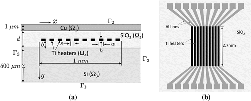
Figure 1. Schematic of the heater array model (a) cross section and (b) top view showing titanium resistive heater lines.
2. Methods
2.1. Model description
A micro-heater array that can be operated in a scanning electron microscope (SEM) is proposed for local temperature control in order to study and control local grain growth.[Citation7] Micro-fabricated heater arrays to generate local temperature gradients, similar to that described here, have been demonstrated previously.[Citation17,Citation18] A schematic of the initial design is shown in Figure . The device is to be fabricated on a standard thick silicon (Si) substrate. Ten titanium (Ti) resistive heating strips will be used to generate a temperature profile along x over a distance of 1 mm in a
thick copper (Cu) film. The heating strips will be relatively long, 2.7 mm, compared to the width, and thus, the temperature field in the central section of the heater array will be essentially two-dimensional in the x–y plane with little variation in the z direction except near the ends of the lines. The titanium heater strips will be embedded in silicon dioxide (
) to insulate the heaters from the Si substrate and Cu film. The width w and thickness h of the Ti heating elements are design parameters, and the thickness of the
, d, and position of the Ti heaters in the
, denoted b, must also be prescribed. When current is delivered to the Ti heaters through aluminium (Al) lines, the volumetric resistive heat generation rate Q in the Ti is
(1)
(1)
where is the temperature-dependent electrical resistivity of the Ti,
is the current density, which can be different in each heater strip, and
is the region occupied by the heater strips.
The usual forward problem is to find the resulting temperature field , which depends on position
where
is the union of all regions in the domain,
–
, at time
given prescribed current densities j in each of the Ti heater lines that satisfies the following system,
(2)
(2)
(3)
(3)
(4)
(4)
(5)
(5)
(6)
(6)
where and
are the material and temperature-dependent thermal conductivity and volumetric heat capacity, respectively,
is the heat flux assuming Fourier’s Law for heat conduction,
is the emissivity on the Cu surface,
is the Stefan–Boltzmann constant,
is the outward unit normal on the boundary
, and the temperature-dependent heat source Q(T) is as defined in Equation (Equation1
(1)
(1) ). Equation (Equation2
(2)
(2) ) represents conservation of energy. The initial condition on the temperature field is represented by Equation (Equation3
(3)
(3) ), and the boundary conditions are given in Equations (Equation4
(4)
(4) )–(Equation6
(6)
(6) ). The temperature is assumed prescribed on the bottom boundary
and a radiation boundary condition on the top boundary
, while the side boundaries,
are treated as insulated. We note that since the micro-heater array is designed to operate in the vacuum environment of an SEM, convection is not considered. The simulation domain was made wide enough in the x direction, so that the boundary conditions on
did not have a significant effect.
The temperature dependency of the material parameters k, C, and
are fit to quadratic functions from experimental data in the literature.[Citation19,Citation20] The temperature dependency of the parameters for each relevant material are as follows. The thermal conductivity k (
) is
(7a)
(7a) The volumetric heat capacity C (
) is
(8a)
(8a) Copper emissivity
is
(9)
(9)
Titanium electrical resistivity (
m) is
(10)
(10)
The temperature T is in K in each of the relations given above.
2.2. Forward problem formulation – finite element model
A standard finite element formulation is used to solve the non-linear forward problem described in Equations (Equation1(1)
(1) )–(Equation6
(6)
(6) ), which is summarized here for completeness. The temperature field is approximated in terms of finite element basis functions at a given time t such that
(11)
(11)
where is a finite dimensional approximation of T,
are finite element basis functions, and
is the number of temperature degrees of freedom (DOF). Greek subscripts refer to finite element basis function numbers, and overbar denotes coefficients of interpolating functions, which are the values of the solution at the finite element nodes. Summation is implied on the repeated index
. Substituting into the standard Galerkin formulation yields the following equation for the temperature field
(12)
(12)
where is a finite dimensional weighting function, which is interpolated with the same functions as the temperature. It should also be emphasized that k, C, Q and
depend on the solution
. After substituting in the finite element interpolations (Equation11
(11)
(11) ), a non-linear system of equations results of the form
(13)
(13)
where represents the vector of nodal temperatures
,
, and
represents its time derivative. This system is linear in
and non-linear in
. The system is integrated in time using a backward difference approximation for the time derivative, and then the resulting non-linear system is solved with a standard Newton–Raphson method at each time. The procedure continues in time until a steady-state temperature is reached.
In simulations of typical micro-heater array designs, it is found that the temperature reaches steady-state very fast relative to the rate at which the microstructure evolves because the domain is very small and thus has a very low thermal inertia. Specifically, steady-state is reached in about 10 ms while grain growth occurs on the scale of minutes and hours. Thus, designing for steady-state (quasi-static) is valid.
2.3. Inverse problem formulation
The inverse problem of interest here is to find the heat source Q that should be applied to each heater strip to generate as close as possible to a desired temperature distribution on the top surface
. Because of the low thermal inertia, we treat the system as quasi-static. The equations to solve for T and Q are then
(14)
(14)
(15)
(15)
(16)
(16)
(17)
(17)
(18)
(18)
We can see from this that we now have over-specified boundary conditions on with both the temperature
and effectively the flux
prescribed approximately. We say approximately because it may not be possible to find a set of heat sources Q that leads to exactly the desired temperature
on
, and thus, we do not strictly enforce that condition. Also note that once the optimal heat source in each heater strip Q is determined, since the temperature will also be known from the solution of the governing equations, the current density j that should be applied in each heater strip may then be backed out from Equation (Equation1
(1)
(1) ).
Since the heat source is only applied in each of the 10 heater strips and is uniform in each strip, we can write(19)
(19)
(20)
(20)
where is the heat source in heater strip i,
is the number of heater strips, and
is the region occupied by heater strip i. Equation (Equation12
(12)
(12) ) can now be written as
(21)
(21)
or symbolically, after substituting in finite element interpolations (Equation11(11)
(11) ), a system of the following form results
(22)
(22)
which is linear in and non-linear in
because k and
depends on T.
The inverse problem can be expressed as the following minimization problem(23)
(23)
where is a matrix that extracts the components of
that are at nodes on
,
are the prescribed values of
at the nodes on
, and the dependency of
on
is defined through Equations (Equation21
(21)
(21) ) and (Equation22
(22)
(22) ).
Because of the non-linear relationship between and
, an iterative solution is required. We linearize Equation (Equation21
(21)
(21) ) approximately by holding
and
fixed in terms of the temperature from the rth inverse iteration leading to the following system after substituting in the finite element interpolations
(24)
(24)
or in matrix form(25)
(25)
where(26a)
(26a)
, and
. Note that
is a symmetric, positive definite matrix.
The function to be minimized in Equation (Equation23(23)
(23) ) to update to iteration
can now be rewritten as
(27)
(27)
where is the sensitivity matrix evaluated at iteration (r) and
is the distance the nodal temperatures are from the target value on
at iteration (r).
Inverse problems are typically ill-posed, which is manifested by instabilities in the solution. Overfitting of the prescribed temperature profile can lead to spatial oscillations in the heat source solution. Here, zeroth-order Tikhonov regularization [Citation21] is used to limit the variability in the solution by augmenting the function to be minimized as follows(28)
(28)
where is the regularization parameter. Finally, minimizing m with respect to
yields our update formula
(29)
(29)
that is used in our inverse analysis to update the heat supply vector at iteration
.
In summary, our inverse analysis algorithm is as follows:
| 1. | Set r = 0, specify an initial guess for | ||||
| 2. | Calculate sensitivity matrix | ||||
| 3. | Find | ||||
| 4. | Solve forward problem (Equation13 | ||||
| 5. | Calculate error norm | ||||
| 6. | If | ||||
2.4. Passivity-based quasi-static feedback control
Considering the system as an input-output relationship, the forward steady-state finite element model can be represented as(30)
(30)
where is a memory-less function representing the mapping from applied heat sources
to the output temperatures
related to
. To retain the same dimension of input and output,
is chosen as the average temperature in each of 10 evenly separated regions on
above the 10 heater strips. In this way, the target temperature profile is reduced to a description with only 10 parameters.
Inspired by the energy dissipating nature of this thermal system, passivity, a powerful tool for stability analysis of non-linear systems, is first analysed. The memory-less system in Equation (Equation30(30)
(30) ) is defined to be passive (in this case, positive semi-definite) if
. It is input-strictly passive (positive definite) if
. where
is a positive scalar. Similar concepts are defined for dynamical systems, e.g. with state space description as
(31)
(31)
where denotes the state,
,
are non-linear functions,
and
are, respectively, output and input. The system is passive if there exists a continuously differentiable positive semidefinite function
(called storage function) so that
(32)
(32)
The Passivity Theorem states that if two passive systems are connected as a negative feedback, (,
), stability of the resulted system around the origin is guaranteed [Citation22]. Moreover, if the memoryless non-linearity
is input-strictly passive, then the connected system is asymptotically stable.
Suppose the target output is and the corresponding input is
, then
. Denoting
,
, then the system can be shifted so that
,
is the origin:
(33)
(33)
where is also a memory-less function. Passivity of
is verified by randomly sampling
around numerous
, input-strict passivity is found to hold for all the samples.
Now, we connect this system with another passive integral controller as negative feedback:(34)
(34)
where is a positive definite matrix. Then the origin is guaranteed to be asymptotically stable. This means that it’s stable and
.
Applying this into a discrete control scheme, the integral controller can be transformed into:(35)
(35)
where is the time interval of the discrete system, which actually can be any value due to the quasi-static nature of the plant. Equation (Equation35
(35)
(35) ) is the iterative formula used to update
, making the output
gradually approach the target
.
Lastly, it remains to define the feedback control matrix and pseudo-time increment
. We combine them into one matrix
. In practice,
can be specified as the following form
(36)
(36)
where is a diagonal with positive entries (known as decentralized feedback).
introduces an augmentation of consensus feedback [Citation23]; it’s a weighted Laplacian of a graph we construct so that every heater is connected to its first, second, third and fourth neighbour. Specifically,
where
is incidence matrix of the graph stated above, and
is a diagonal weighting matrix. The augmentation of
allows the feedback to penalize the difference between entries of
, so that in the process of converging to
, the shape of the intermediate profile is kept close to the desired one.
The iterative formula in Equation (Equation35(35)
(35) ) is different from the one in the inverse problem method, Equation (Equation29
(29)
(29) ), as the coefficient matrix
is fixed for all iterations while the analogous coefficient matrix
is updated at the beginning of each iteration in the inverse analysis. The feedback control algorithm follows the same basic steps as those in the inverse problem method listed at the end of Section 2.3, where Equation (Equation35
(35)
(35) ) is used in place of Equation (Equation29
(29)
(29) ).
3. Results and discussion
3.1. Forward model analysis and design
Before solving the inverse problem to determine the required heat input into each heater strip in the micro-heater array, the geometric design parameters w, h, d and b must be specified (see Figure (a)). Of these, the most critical are w and h defining the cross-sectional dimensions of the heater strips. The cross section of the heater strips must be such that they can carry enough power per unit length to generate sufficient heat to cause grain growth in the Cu film while keeping the current density sufficiently small to avoid electromigration-induced failure in the Al and Ti lines. The power per unit length P is(37)
(37)
where I is the current in a line and is a heater strip cross-sectional area. In addition, the lines should be sufficiently wide, or the gap between the lines
(pitch
m), sufficiently small, so that the temperature profile is smooth.
Grain growth in copper films occurs on a time scale of tens of minutes in the range 300–, which is on par with the time scale required for experimental observations. Thus, the heater array should be able to bring the temperature in the copper to this range and should allow for a gradient of at least
over the 1 mm domain so that a gradient in the microstructure may be created. To limit the required heat generation from the micro-heater array, the device can be placed on a heating stage that can bring the initial temperature to
and maintain this temperature on
, i.e.
. Then the micro-heater array only needs to raise the temperature
to cause grain growth. From forward simulations, it was determined that the minimum required power per unit length to achieve this is
. In the temperature range of interest,
, and thus from Equation (Equation37
(37)
(37) )
.
To avoid electromigration failure, the current density j must be limited and the surrounding should be sufficient to contain the line without cracking under stress due to electromigration-induced diffusion of either the Al or Ti. While there have been many studies of electromigration in Al conductor lines,[Citation24,Citation25] electromigration in Ti lines has not been studied. Based on available Al data and estimating the electromigration behavior in Ti, we estimate that electromigration will not be significant if the current density is kept at
provided the
has a thickness of at least
above the Ti lines. To satisfy the power requirement
and the current density requirement
,the current must be limited such that
A and the cross-sectional area must be
. A design that satisfies all of these requirements is
(
),
,
, and
.
Now that the micro-heater array geometry is completely defined, it must be discretized into a finite element mesh for both the forward and inverse finite element analysis. The mesh must be sufficiently refined to maintain a satisfactory accuracy in the forward solution. A mesh convergence study was performed, and a mesh with 1540 four-node quadrilateral elements was found to be adequate to generate a solution accurate to within . A graded mesh was used that is highly refined near the top where the heat is generated and coarse near the bottom of the Si substrate. The uncertainty due to the finite element approximation is relatively small compared to uncertainty in the physical model. For example, there is uncertainty in the layer thicknesses because of the fabrication process, and the resistivity in the Ti lines shows variability due to microstructure and imperfections. Model calibration to experiments will be done as the experiments come on-line, and the model uncertainty will be more precisely quantified.
Results from a transient forward simulation are shown in Figure where a uniform current of A is prescribed in each heater strip for a current density of
. From this plot, we see that steady-state is achieved in about 10 ms, the temperature is elevated by
to about
in the central part of the region above the heater array, but drops off near the edges due to the heat conducting away on the sides. We also see that the temperature profile is not completely smooth with small bumps in the temperature above each heater and dips in between.
Figure 2. Evolution of the temperature distribution on the top surface for a uniform current of
A in each heater strip.
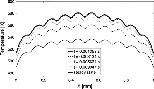
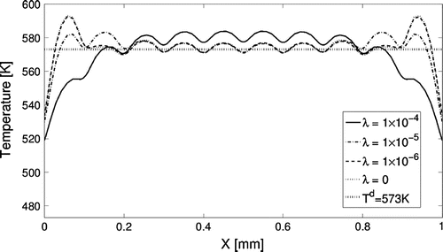
Figure 3. Temperature distribution on the top of the copper thin film from inverse analysis with different regularization parameters. The units for the regularization parameter are (.
3.2. Inverse problem solution
In this section, we compare the two methods for solving the inverse heat transfer source problem described in Sections 2.3 and 2.4, direct minimization and feedback control, solving problems relevant to the micro-heater array design. Specifically, we consider the cases of finding the required heater settings for generating a prescribed uniform temperature of and a linear gradient of
, where part of the distribution is above
.
The goal of the inverse problem is to find the heat source, and thus the current, that must be applied to each micro-heater in the array to achieve a desired temperature distribution on the top surface. In the inverse analysis approach with regularization, the regularization parameter must be selected large enough to generate a smooth, stable solution, but not so large as to drive the solution away from satisfying the objective function. To show the effect of the regularization parameter, we first solve the inverse problem for a prescribed uniform temperature distribution of
(573 K) on the top surface with varying values for
. Since the regularization parameter is added on the diagonal to
in Equation (Equation29
(29)
(29) ), it should not be very large compared to those diagonal elements, which in this case are on the order of
(
. Thus, regularization parameters considered were near this order of magnitude. The results are shown in Figures and . Figure shows the resulting temperature profile on the surface. As the regularization parameter
increases, the temperature at both ends decreases, and the overall shape of the temperature profile becomes smoother, though the small peaks with respect to the micro-heaters remain. While it is possible to obtain a solution close to the prescribed temperature near the centre of the domain, it is not possible near the edges. When the regularization parameter is too high, the solution starts to move further away from the target temperature
. There is almost no difference between the result without regularization and when the regularization parameter is set at
(
.
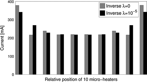
In addition, we calculated the condition number of at convergence and found it to be 9.1, which indicates very weak instability of solution [Citation26] and is consistent with the relatively small oscillations observed even with no regularization. In Figure , the current input I to each heater is plotted for the cases with
and
, where I is computed from the heat source Q solved for in each heater using Equation (Equation1
(1)
(1) ) and
. Without regularization, oscillations in the required current occur at the ends with a large spike in the current predicted for the heaters at the ends. Such spikes are undesirable from a practical point of view because high current densities may lead to rapid failure of the lines. The current distribution near both ends becomes smoother as
changes from 0 to
.
We also wanted to see if we could get a good solution ignoring the non-linearity, and instead, solve a linear system setting the material parameters at the target temperature of . When we did this, we found the solution for the optimal current input to each line deviated by as much as 30% from the value found including the non-linearity. Thus, for an accurate solution, the non-linear material behaviour is very important.
Figure 4. Currents in the 10 heaters from the solution of inverse analysis for and
. The units for the regularization parameter are (
.
To quantitatively evaluate the deviation of the solution from the prescribed temperature
on the copper thin film surface, we set a metric
by calculating the standard deviation as
(38)
(38)
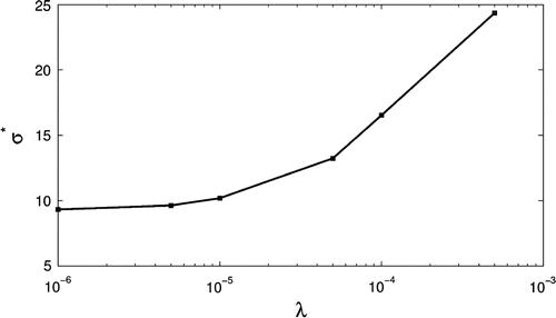
Figure shows the metric for varying regularization parameters. In addition,
K for the case with the regularization parameter
= 0. It is shown that
increases with
, which means the solution increasingly deviates from the prescribed temperature as
increases. Therefore, there is a trade-off between the smoothness of the profile and the minimization of the metric
. However, we also see that
does not increase significantly until
, and thus, this appears to be an optimal value. Solving the inverse problem with
leads to a relatively small metric
(
10 K) and a relatively uniform temperature profile on the surface of the area of interest.
Figure 5. Comparison of standard deviation of (K) as regularization parameter
(
varies.
To solve the inverse problem with the feedback control strategy, it remains only to define the diagonal matrices and
. Both of these matrices are set with constant values on the diagonals, with the diagonal elements of
set at
-K) and those of
set at
-K).
We now compare the results and performance for the inverse problem and feedback control approaches for two cases, one with the objective of creating a uniform temperature profile, as described earlier when investigating the effect of the regularization parameter, and one with the objective of creating a linear temperature profile. Although the inverse analysis and the feedback control approach both use an iterative scheme to find the optimal solution for the heat sources, the difference in the update equations leads to dissimilarity in their performance.
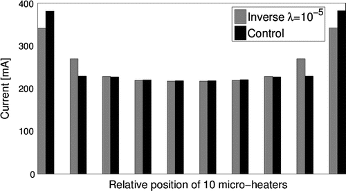
Figures and present the results for the case with the target of a uniform temperature profile. In Figure , the resulting temperature profiles are shown. The results in the central region for both methods are nearly identical, and the results only deviate near the ends, above the last two heaters at each end. The feedback control generates a higher peak at the end, which is similar to the inverse analysis result without regularization shown in Figure . In Figure , the current input I to each heater is plotted. We see that the two micro-heaters near both ends of the area of interest have relatively large values, especially for the solution from the feedback control. As mentioned in Section 3.1, we would like to keep the current density to reduce the likelihood for failure by electromigration for the given cross-section geometries, that corresponds to
mA. We can see in Figure that the currents exceed the recommended limit in the last heaters on the ends because these heaters have to provide more heat to compensate for loses due to lateral conduction. This may not be a major issue as the resistivity
in the Ti lines assumed here is a reported value for bulk Ti, and the resistivity in the 400 nm thick heater strips is likely to be higher, thus requiring less current to generate the same amount of heating. In fact, preliminary experimental measurements of the resistance in the Ti lines for fabricated micro-heaters shows a resistance of approximate twice the bulk value. In addition, a relatively thick layer of
is used, which also will act to hinder electromigration.
Figure 6. Comparison of temperature distribution of nodes on the top of the copper thin film between the inverse analysis and feedback control approachs.
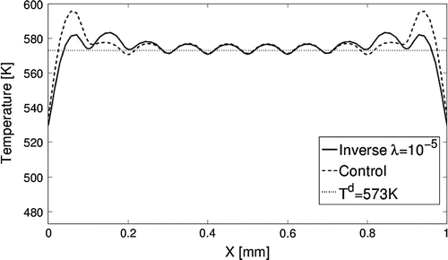
Figure 7. Comparison of currents in the 10 heaters between the inverse analysis and the feedback control approachs.
As for the computational efficiency, the inverse analysis with regularization converges to the solution faster than the feedback control method. Figure shows that the inverse analysis converges after five iterations, and for the feedback control it takes about eight iterations. Most likely this is due to their difference in solving the iterative formula. In Equation (Equation29(29)
(29) ), e.g. the iterative formula of the inverse analysis, the coefficient matrix
is updated in each iteration. However, for feedback control, Equation (Equation35
(35)
(35) ) uses a predefined feedback matrix
, which is fixed in all iterations. Therefore, the inverse analysis captures the temperature dependence of the model better than the feedback control, speeding up the convergence. On the other hand, fewer computations are required in each iteration for the feedback control strategy because
only needs to be evaluated once.
Figure 8. Comparison of the standard deviation at different inverse analysis or feedback control steps.
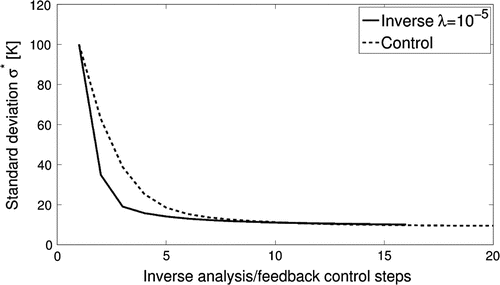
Figure 9. Comparison between the inverse analysis results using (
and feedback control results for reaching a linear temperature profile.
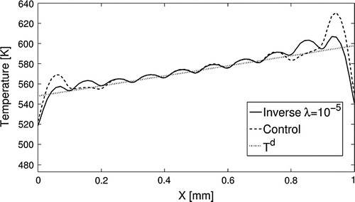
In addition, we compared the performance between the inverse analysis with regularization and feedback control methods for reaching a linear temperature profile as shown in Figure . Here, the prescribed temperature distribution is a linear distribution that varies over the range 275– (547–598 K), i.e. a temperature gradient of
across the 1 mm area of interest. The solution of the inverse analysis is regularized by the same regularization parameter (
(
) as before. From Figure , both the inverse analysis and feedback control are able to drive the temperature at the centre region close to the prescribed temperature profile
in the central region with peaks and a rapid drop-off near the ends, similar to the results for the constant profile case. As in the previous case, the feedback control method has larger spikes at the ends, which are smoothed with regularization.
4. Conclusion
In this paper, we present two methods to solve the inverse heat source problem to find the optimal current inputs to elements in a micro-heater array to achieve a prescribed temperature field that may be used to control microstructure evolution. First, we show that the micro-heater array reaches a steady-state temperature field in about 10 ms, which is negligible compared to the grain growth experiment time frame of minutes and hours. Thus, the feed-forward control problem of finding the current as a function of time that should be applied to each heater element to achieve a prescribed temperature profile history, can be reduced to solving the steady-state problem at discrete times. A direct inverse method with zeroth-order Tikhonov regularization and a passivity-based feedback control method were developed, used to solve two cases of the inverse problem, and compared. The methods are based on a non-linear finite element model of the micro-heater array. Both methods performed well.
The accuracy of the finite element model in representing the actual physical system must be tested. For example, early tests show that the resistivity in the Ti heater lines is roughly twice that reported for bulk Ti used here. Thus, it is expected that the forward finite element model will require refinement as data becomes available. The experimental data can also be used to quantify the model uncertainty which may be used to estimate uncertainty in the solution for the required heater settings using Bayesian methods.
Nevertheless, the model has proven useful in generating an initial design for a micro-heater array, and the methods to solve the inverse problem can be applied to the refined model to generate improved estimates for the required currents for different temperature profiles for feed-forward control. The results show that both a uniform and a linear temperature distribution can be attained near the central part of the region of interest, but it is not possible to match the temperatures well at the edges of the region. If we want to accurately control the temperature field over the full 1 mm region, the heater array must extend beyond this region with either more or wider heater elements. Comparing the inverse analysis with the feedback control approach, we found that the inverse analysis generated a smoother distribution of current inputs and resulting temperature field due to the regularization. The feedback control algorithm was relatively simpler because the coefficient matrix used to solve for the heat source update was fixed for all iterations, but required more iterations to converge.
5. Nomenclature
Q volumetric heat generation rate
T temperature
vector of heat sources in each heater strip
j current density in a heater strip
k thermal conductivity
C volumetric heat capacity
w width of the Ti heating elements
h thickness of the Ti heating elements
d thickness of the
b position of the Ti heaters in the
P power per unit length of a heater strip
A heater strip cross-sectional area
p pitch of heater strips
I current in a heater strip
s gap between heater strips
r iteration number
Additional information
Funding
Notes
No potential conflict of interest was reported by the authors.
References
- International Copper Association. Copper applications technology roadmap. International Copper Association; 2011. Retrieved from http://copperalliance.org/wordpress/wp-content/uploads/2012/02/technology\_roadmap.pdf
- Alluminium Association. Aluminum industry technology roadmap. The Aluminum Association; 2003. Retrieved from http://bibvir2.uqac.ca/archivage/18237523.pdf
- Humphreys FJ, Hatherly M. Recrystallization and related annealing phenomena. 2nd ed. Oxford: Elsevier; 2004.
- Griffin Jr AJ, Brotzen FR, Dunn C. Hall--Petch relation in thin film metallizations. Scr. Metall. 1986;20:1271–1272.
- Witkin D, Lee Z, Rodriguez R, et al. Al--Mg alloy engineered with bimodal grain size for high strength and increased ductility. Scr. Metall. 2003;49:297–302.
- Findley KO, Saxena A. Low cycle fatigue in Rene 88DT at 650°C: crack nucleation mechanisms and modeling. Metall. Mater. Trans. A. 2006;37A:1469–1575.
- Zheng C, Balasubramanian GPS, Tan Y, et al. Simulation, microfabrication and control of a micro-heater array. IEEE/ASME Trans. on mechatronics. submitted. 2016;1–6.
- Le Niliot C, Lefèvre F. A parameter estimation approach to solve the inverse problem of point heat sources identification. Int. J. Heat Mass Trans. 2004;47:827–841.
- Yang CY. The determination of two moving heat sources in two-dimensional inverse heat problem. Appl. Math. Model. 2006;30:278–292.
- Martin TJ, Dulikravich GS. Inverse determination of boundary conditions and sources in steady heat conduction with heat generation. Trans. ASME, J. Heat Trans. 1996;118:546–554.
- Yan L, Fu CL, Dou FF. A computational method for identifying a spacewise-dependent heat source. Int. J. Numer. Methods Biomed. Eng. 2010;26:567–608.
- Jiang H, Nguyen TH, Prud’homme M. Optimal control of induction heating for semi-solid aluminum alloy forming. J. Mater. Process. Technol. 2007;189:182–191.
- Chen TC, Cheng CH, Jang HY, et al. Using input estimation to estimate heat source in nonlinear heat conduction problem. J. Thermophys. Heat Transfer. 2007;21:166–172.
- Oden JT, Diller KR, Bajaj C, et al. Dynamic data-driven finite element models for laser treatment of cancer. Numer. Methods Partial Differ. Equ. 2007;23:904–922.
- Frackowiak A, Botkin ND, Ciałkowski M, et al. Iterative algorithm for solving the inverse heat conduction problems with the unknown source function. Inverse Prob. Sci. Eng. 2015;23:1056–1071.
- Isakov V. Inverse source problems. Providence (RI): American Mathematical Society; 1990.
- Darhuber AA, Troian SM, Wagner S. Generation of high-resolution surface temperature distributions. J. Appl. Phys. 2002;91:5686–5693.
- Darhuber AA, Valentino JP, Troian SM, et al. Thermocapillary actuation of droplets on chemically patterned surfaces by programmable microheater arrays. J. Microelectromech. Syst. 2003;12:873–879.
- Touloukian Y, Liley P, Saxena S. Thermophysical properties of matter: the tprc data series: a comprehensive compilation of data. New York (NY): IFI/Plenum; 1970.
- Bel’skaya EA. An experimental investigation of the electrical resistivity of titanium in the temperature range from 77 to 1600 K. High Temp. 2005;43:546–553.
- Tikhonov AN, Arsenin VY. Solution of ill-posed problems. New York (NY): Wiley; 1977.
- Khalil HK, Grizzle J. Nonlinear systems. Vol. 3. Upper Saddle River (NJ): Prentice Hall; 1996.
- Bamieh B, Jovanovic MR, Mitra P, et al. Coherence in large-scale networks: dimension-dependent limitations of local feedback. IEEE Trans. Autom. Control. 2012;57:2235–2249.
- Wang PC, Cargill III G, Noyan I, et al. Electromigration-induced stress in aluminum conductor lines measured by X-ray microdiffraction. Appl Phys Lett. 1998;72:1296–1298.
- Zhang H, Cargill III GS, Ge Y, et al. Strain evolution in Al conductor lines during electromigration. J. Appl. Phys. 2008;104:123533-1–123533-10.
- Aster RC, Borchers B, Thurber CH. Parameter estimation and inverse problems. Waltham (MA): Academic Press; 2011.