 ?Mathematical formulae have been encoded as MathML and are displayed in this HTML version using MathJax in order to improve their display. Uncheck the box to turn MathJax off. This feature requires Javascript. Click on a formula to zoom.
Abstract
In this study, dynamic moving load identification of laminated composite beams is performed by introducing a hybrid finite element (FE), time marching differential quadrature (TMDQ) and genetic algorithms (GAs) methods. The first-order shear deformation theory based equations of the beam are discretized in the space and time domains using the FE and TMDQ methods, respectively. Accuracy and efficiency of the TMDQ method for solving the problem are shown via comparing the results with the Newmark’s method. To simulate the measured responses for the load identification problem, random error is applied to the dynamic responses obtained from the finite element and time marching differential quadrature method under a given dynamic load. An objective function as a root mean square error between the calculated and measured responses is defined and the GAs is employed to minimize the function and identify the loading parameters. Applicability and usefulness of the proposed method are shown through solving some examples.
1. Introduction
Dynamic load identification is an important problem for design and remaining lifetime assessment of structures [Citation1–6]. Due to the complexity of the structures and environmental factors in many practical applications, it is difficult or impossible to measure the load directly [Citation4,7,8]. However, it is possible to indirectly estimate the applied loads by measuring the dynamic responses of structures such as natural frequencies and time history responses. Several approaches were proposed to identify the time-history of a moving force, using inverse techniques.
Qiao et al. [Citation9,10] employed a sparse regularization method to identify the time history of impact force and its location. Yan and Zhou [Citation11] used a genetic algorithms-based approach for identification of load location and its history for composite structures. Feng et al. [Citation12] presented a numerical method to simultaneously identify the structural parameters and vehicle axle load histories, on beam-type bridges using a limited number of response measurements. Law et al. [Citation13] introduced an analytical solution based on modal superposition to identify the vertical dynamic interaction forces between a moving vehicle and the bridge deck in the time domain, assuming a simply supported beam for the deck. Zhu and Law [Citation14] used the modal superposition principle to analysis the dynamic behaviour of the bridge deck under moving loads. The identified results using a beam model and a plate model of the bridge deck were compared, and the conditions under which the bridge deck can be simplified as an equivalent beam model were discussed. A finite element approach with updated static component technique was proposed by Pinkaew [Citation15] to identify the moving loads. Wu and Law [Citation5] and Zhu et.al [Citation8] used a finite element (FE) approach with the Newmark’s time integration scheme for discretization of equation of motion in a load identification problem.
In the most of the above articles the Euler–Bernoulli beam model are considered. However, by increasing the height to thickness ratio of the beam Timoshenko beam theory can give better responses [Citation7,16]. Hence, in the present study the Timoshenko beam model is used to introduce the inverse procedure. Among the various approaches used for load identification, the FE method as an efficient numerical tool is preferred to discretize the governing equations and the related boundary conditions [Citation17–19]. In this regard, usually the Newmark’s time integration scheme is employed [Citation5,8]. However, a recently developed differential quadrature method (DQM) was shown to have much higher accuracy for dynamic analysis of structures [Citation20–22]. Therefore, in the present study a new hybrid method based on finite element and time marching differential quadrature (FE-TMDQ) methods is proposed for dynamic analysis of laminated composite beams. The first-order shear deformation beam theory is used to obtain the governing equations of the beam subjects to a moving load. The FE method is used to discretize the governing equations in space domain. The time marching differential quadrature and Newmark’s time integration methods are then employed to solve the problem in time domain. The obtained responses of these two methods are compared to demonstrate the accuracy and efficiency of the proposed hybrid FE-TMDQ method. To identify the applied load on the laminated composite beams, an error function as root mean square error (RMSE) between measured and calculated responses is assumed. The measured responses are obtained by applying random error to the calculated responses using the FE-TMDQ method. Then, the dynamic load parameters are obtained by minimizing the error function using genetic algorithms (GAs) as a stochastic iterative search method which can make global solution search as opposed to classical gradient-based optimization techniques [Citation18–20]. Finally, the applicability and usefulness of the proposed strategy are proved through some examples.
2. Problem formulations
2.1. Governing equations
A laminated composite beam consisted of perfectly bounded orthotropic layers of length L, width b and total thickness h is considered (Figure ). According to the first-order shear deformation theory the governing equations of beams can be obtained as follows [Citation16].(1)
(1)
(2)
(2)
where(3a–d)
(3a–d)
here w is the displacement component of the mid-plane point along the z-axis, φx is the rotation of the section normal to the mid-plane about the y axis, ks is the shear correction factor and ρ(i) is the density of the ith layer, and and
are the generalized reduced stiffness components of the ith layer.
2.2. Finite element formulation
Using the finite element method and the linear interpolation functions, and
, the governing equations (Equations (1) and (2)) can be discretized for an element of the beam, as follows:
(4)
(4)
where(5a–h)
(5a–h)
After assembling of the element matrices, the global semi-discrete equation of motion can be obtained:(6)
(6)
where and
are the nodal displacement and nodal acceleration vectors, respectively.
,
and
are the global mass matrix, the global stiffness matrix and the time history of the applied nodal force vector. Here, the Newmark’s scheme and time marching DQM are used for time domain discretization of Equation (6). More details of these methods are described below.
2.3. Newmark’s solution
In the Newmark’s method, velocities and accelerations of nodes at step s + 1 is related to those quantities at step s;(7-a)
(7-a)
(7-b)
(7-b)
where ,
and
are approximations of the displacement, velocity, and acceleration vectors at time step s, respectively. Also, α and
are the parameters which determine the stability and accuracy of the method. By using these approximations in the Equation (6), one can obtain:
(8)
(8)
where(9a-b)
(9a-b)
It should be noted that calculation of and
, requires acceleration vector at the initial condition. In practice
is not known, but can be obtained from:
(10)
(10)
Here the Newmark’s parameters, α and γ are assumed to be 3/2and 8/5, respectively, which results an unconditional stable solution.
2.4. TMDQ solution
The main idea behind using of the DQM is discretizing the domain into a number of points called nodes, then converting the time derivative of a function in each point to the weighted summation of the function on all nodes of the domain. One of the drawbacks of the conventional DQM is discretizing the whole time domain simultaneously, which increase the computational costs. To overcome this problem the whole time domain is divided into a number of subdomains, NIT. In each subdomain the conventional DQM is utilized and the responses (displacement, velocity and acceleration) at the end of each subdomain are used as the initial conditions for the next subdomain. This procedure, called as time marching DQM, would be repeated until the response of the problem is obtained, at the specified time step. More details can be seen in [Citation21–27]. According to the time marching DQM, at each time step (ti) the velocity and acceleration, can be approximated as follows:(11a-b)
(11a-b)
Here, NT is the number of nodes in each time subdomain and and
are the first and second weight coefficients.
(12-a)
(12-a)
(12-b)
(12-b)
where
, and U1 and
are the initial values. T is the time length of each time subdomain. The distribution of nodes in each time step is assumed to obey the Chebyshev–Gauss–Lobatto node distribution as follows:
(13)
(13)
where ti is the time of ith point of the time subdomain with length of T.
By substituting the expression of Equation (Equation11(11a-b)
(11a-b) ) into the spatially discretized equation of motion (Equation (6)), an algebraic expression is obtained for the equation of motion, which can be used to calculate the responses of the problem at each subdomain.
2.5. Load identification procedure
The magnitude and velocity of the applied concentrated dynamic moving load on the laminated composite beam can be obtained by minimizing the following error function.(14)
(14)
where and
are the calculated and measured displacements at the specified locations of the beam, respectively. M is the number of points at which the response is measured. The measured data for the load identification procedure are obtained by applying random error to the responses calculated under a given dynamic moving load using the approaches of the previous sections. In order to minimize the above objective or fitness function (Equation (12)), GAs as a global solution search method is used. In these techniques the difficulties of choosing best starting values for the magnitude and velocity of the applied loads, being necessary in traditional optimization techniques for converging to the global minimum, are completely overcome. In the GAs first initial population is generated and the error function is calculated with respect to the obtained values, by using tournament selection, cross over and mutation new population is generated and the function value would calculate again. This procedure would be repeated until the following convergence criterion is satisfied.
(15)
(15)
where EFz+1and EFz are the best (minimum) values of the objective functions at the z + 1th and zth iterations, respectively.
3. Numerical results
In this section, first, convergence and accuracy of the FE-DQ and FE-Newmark’s methods for the dynamic analysis of laminated composite beams are illustrated and compared with each other. Then, applicability, usefulness and convergence of the hybrid FE-DQ-GAs method for dynamic load identification of the beam are studied.
3.1. Dynamic analysis of composite beam
The dynamic response of the composite beam is considered under a sinusoidal concentrated vertical dynamic load as follows:
where is the angular frequency, Tf is the time of applying the dynamic load which is a portion of total time of dynamic analysis (
) and v is the constant moving velocity along the x-axis.
To do so, two different boundary conditions are considered for the edges of the beam, as follows:
| (a) | Simply (S) supported edge: w = 0, | ||||
| (b) | Clamped (C) edge: w = 0, φx = 0. | ||||
Also, two different materials are assumed to generate the numerical results:
Mat. I:
Mat. II:
In Table , the convergence of the finite element method with the Newmark’s time integration scheme for dynamic analysis of laminated composite beam for different length to height ratio under a concentrated sinusoidal load are presented. Mat. II was assumed for the beam with Tf = Tt/4, which means that the load is applied during one fourth of the total time of dynamic analysis. As it has been shown, the acceptable results are achieved using 20 elements in the space domain. So, hereafter Ne = 20 is used for finite element discretization of all the solved problems.
Table 1. The effects of element number on convergence of non-dimensional vertical displacement of the midpoint 
 of three layers laminated composite beam [0°/90°/0°], for different L/h ratio, and Tf = Tt/4.
In Table , the computational times and the non-dimensional vertical displacement,, of the midpoint of beam (
), Wcc, obtained from the TMDQ and Newmark’s methods are shown for different NT and NIT. It is assumed that beam is made from Mat. I with L/h = 10. According to the obtained results, computational time of TMDQ method is less than those of Newmark’s method. So, the DQ method is more efficient for the time domain analysis of the problem.
Table 2. Comparison between convergence and computational time of non-dimensional vertical displacement of the midpoint of beam 
 for Newmark and TMDQ Methods, for different NT and NIT, and assuming Mat. I, L/h = 10, Ne = 20 and Tf = Tt/2.
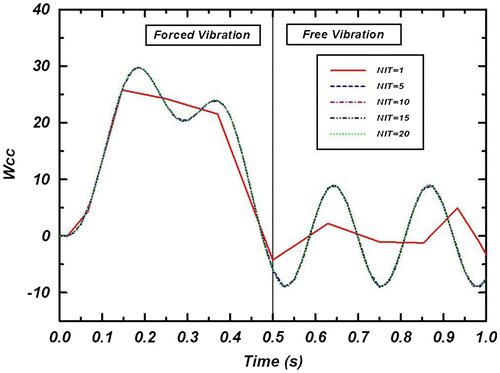
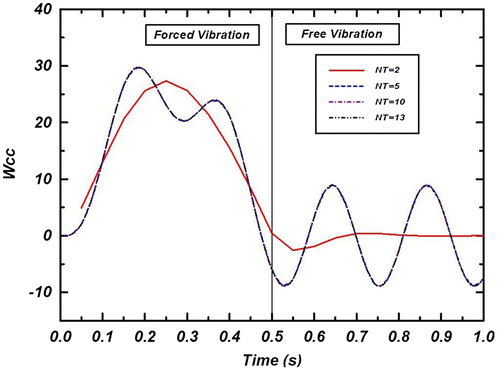
In Figures and , the effects of NIT and NT on the convergence of non-dimensional dynamic response of isotropic beam are shown, respectively. From these figures it can be concluded that NT = 13 and NIT = 20 are sufficient to obtain the converged solutions
3.2. Loading parameters identification
In order to study the convergences of proposed method for solving the inverse problem of dynamic load identification, different errors (with maximum +5 and +10% noise) are applied to the responses predicted by the combined FE-TMDQ method with a given dynamic moving load. The different noise values which selected randomly, along with the average (AVE) and standard deviation (SD) of the applied random errors are shown in Table . Three scenarios are considered here, (a) one sensor which measures the response at L/2 of the beam, (b) two sensors which measure the response at L/4 and L/2 of the beam and (c) three sensors which measure the response at L/4, L/2 and 3L/4 of the beam. The noisy responses are used as the measured values in the objective function (Equation (12)). Then the GAs is used to identify the applied dynamic load by minimizing the objective function. Probabilities for the crossover and the mutation operators of the GAs are considered to be 50%.
Table 3. The applied random error for simulating measured responses using different sensors numbers.
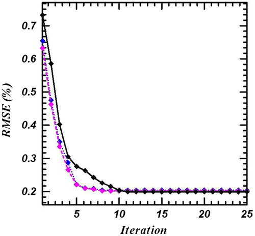
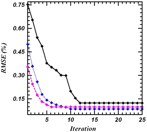
The convergences of the method for different initial populations and different noises are shown in Figures , and . As it could be seen, the proposed strategy has good convergence and accuracy for different initial populations. Also, the effect of fibre alignments and different boundary conditions on the identified loading parameters, i.e. the magnitude, frequency and rate of the concentrated sinusoidal load, assuming maximum 5% error are shown in Tables . Here the exact values of the loading parameters are assumed to be P0 = 1, V = 2 and . The beam is assumed to have the length to height ratio of
, and made from Mat. II. In Tables , the angular frequency
, is taken to be as a known parameter and two other loading parameters i.e. P0 and V are identified employing GAs. As it can be seen from these Tables, the proposed approach has good accuracy and convergence for different boundary conditions. In Table , the frequency of the concentrated sinusoidal load is also identified using the proposed approach. Moreover, the load parameters of the following triangular type load,
Figure 4. Convergence of method for different initial population size: 10:; 20:; 30:; using 5% noise (Mat. II, L/h = 10, Ne = 20, NIT = 20, Tf = Tt/2).

Figure 5. Convergence of combined method for different initial population size: 10:; 20:; 30:; using 10% noise load (Mat. II, L/h = 10, Ne = 20, NIT = 20, Tf = Tt/2).

Table 4. The magnitude and rate of load predicted for different number of measured responses and different fibres orientations of simply supported laminated composite beam using 5% noise (Mat. II, L/h = 10, Ne = 20, NIT = 20, Tf = Tt/2).
Table 5. The magnitude and rate of load predicted for different number of measured responses and different fibres orientations of fixed at both ends laminated composite beam using 5% noise (Mat. II, L/h = 10, Ne = 20, NIT = 20, Tf = Tt/2).
Table 6. The magnitude and rate of load predicted for different number of measured responses and different fibres orientations in clamped-simply supported laminated composite beam using 5% noise (Mat. II, L/h = 10, Ne = 20, NIT = 20, Tf = Tt/2).
Table 7. Identified load parameters for different number of measured responses and different fibres orientations of simply supported laminated composite beam using 5% noise (Mat. II, L/h = 10, Ne = 20, NIT = 20, 
 ).
).
for different fibre alignments are identified and the results are presented in Table . These results show the generality of approach to identifying the magnitude and pattern of the loads completely. So the proposed combination can be successfully used to determine the parameters of dynamic problems, with lower computational cost in comparison to the Newmark’s method.
Table 8. Identified triangular type load parameters for different number of measured responses and different fibres orientations of simply supported laminated composite beam using 5% noise (Mat. II, L/h = 10, Ne = 20, NIT = 20, 
 ).
).
4. Conclusions
This paper presented a new hybrid inverse approach to identify dynamic moving loads on laminated composite beam using the finite element (FE), differential quadrature (DQ) and Genetic algorithms (GAs) methods. The concentrated dynamic load is represented by a sine wave, travelling with a constant velocity on the top surface of the composite beam. The governing equations of the beam under moving load is obtained by using the Timoshenko beam theory and the FE method with the time marching TMDQ and Newmark’s time integration methods are employed to discretize the equations of motion. It is found that combined FE-TMDQ method has more accuracy and low computational costs for solving the dynamic response of the problem. The dynamic response of the structure subject to a known force, with some noise is taken as a measured response. By minimizing the differences between the measured dynamic response and the responses of identified forces by GAs, the applied load on beam is determined. The effectiveness and convergence of this new identification strategy is demonstrated by simulation studies on laminated composite beams with different configuration and materials properties, and different boundary conditions.
Disclosure statement
No potential conflict of interest was reported by the authors.
References
- Moaveni B, He X, Conte JP, et al. Damage identification of a composite beam using finite element model updating. Comput Aided Civ Infrastruct Eng. 2008;23:339–359.
- Thite AN, Thompson DJ. Selection of response measurement locations to improve inverse force determination. Appl Acoust. 2006;67:797–818.10.1016/j.apacoust.2006.01.001
- Yan G. A Bayesian approach for impact load identification of stiffened composite panel. Inv Prob Sci Eng. 2014;22:940–965.10.1080/17415977.2013.848431
- Wang L, Han X, Xie Y. A new conjugate gradient method for solving multi-source dynamic load identification problem. Int J Mech Mater Des. 2013;9:191–197.10.1007/s10999-012-9208-4
- Wu SQ, Law SS. Vehicle axle load identification on bridge deck with irregular road surface profile. Eng Struct. 2011;33:591–601.10.1016/j.engstruct.2010.11.017
- Sun H, Feng D, Liu Y, et al. Statistical regularization for identification of structural parameters and external loadings using state space models. Comput Aided Civ Infrastruct Eng. 2015;30:843–858.10.1111/mice.12169
- Law SS, Zhu XQ. Study on different beam models in moving force identification. J Sound Vib. 2000;234:661–679.10.1006/jsvi.2000.2867
- Zhu T, Xiao Sh, Yang GW. Force identification in time domain based on dynamic programming. Appl Math Comput. 2014;235:226–234.
- Qiao B, Zhang X, Gao J, et al. Impact-force sparse reconstruction from highly incomplete and inaccurate measurements. J Sound Vib. 2016;376:72–94.10.1016/j.jsv.2016.04.040
- Qiao B, Zhang X, Gao J, et al. Sparse deconvolution for the large-scale ill-posed inverse problem of impact force reconstruction. Mech Syst Signal Process. 2017;83:93–115.
- Yan G, Zhou L. Impact load identification of composite structure using genetic algorithms. J Sound Vib. 2009;319:869–884.10.1016/j.jsv.2008.06.051
- Feng D, Sun H, Feng MQ. Simultaneous identification of bridge structural parameters and vehicle loads. Comput Struct. 2015;157:76–88.10.1016/j.compstruc.2015.05.017
- Law SS, Chan THT, Zeng QH. Moving force identification: a time domain method. J Sound Vib. 1997;201:1–22.10.1006/jsvi.1996.0774
- Zhu XQ, Law SS. Identification of vehicle axle loads from bridge dynamic responses. J Sound Vib. 2000;236:705–724.10.1006/jsvi.2000.3021
- Pinkaew T. Identification of vehicle axle loads from bridge responses using updated static component technique. Eng Struct. 2006;28:1599–1608.10.1016/j.engstruct.2006.02.012
- Reddy JN. Mechanics of laminated composite plates and shells. Theory and analysis. New York: CRC Press; 2004.
- Law SS, Bu JQ, Zhu XQ, et al. Vehicle axle loads identification using finite element method. Eng Struct. 2004;26:1143–1153.10.1016/j.engstruct.2004.03.017
- Vosoughi AR. A developed hybrid method for crack identification of beams. Smart Struct Syst. 2015;16:401–414.10.12989/sss.2015.16.3.401
- Vosoughi AR, Gerist S. New hybrid FE-PSO-CGAs sensitivity base technique for damage detection of laminated composite beams. Compos Struct. 2014;118:68–73.10.1016/j.compstruct.2014.07.012
- Eftekhari SA, Jafari AA. Mixed finite element and differential quadrature method for free and forced vibration and buckling analysis of rectangular plates. Appl Math Mech. 2012;33:81–98.10.1007/s10483-012-1535-6
- Vosoughi AR, Malekzadeh P, Razi H. Response of moderately thick laminated composite plates on elastic foundation subjected to moving load. Compos Struct. 2013;97:286–295.10.1016/j.compstruct.2012.10.017
- Vosoughi AR, Nikoo MR. Maximum fundamental frequency and thermal buckling temperature of laminated composite plates by a new hybrid multi-objective optimization technique. Thin Wall Struct. 2015;95:408–415.10.1016/j.tws.2015.07.014
- Vosoughi AR. Nonlinear free vibration of functionally graded nanobeams on nonlinear elastic foundation. IJST, Trans Civil Eng. 2016;40:23–32.
- Vosoughi AR. Thermal postbuckling analysis of functionally graded beams. J Therm Stresses. 2014;37:532–544.10.1080/01495739.2013.872462
- Malekzadeh P, Monfared Maharloei H, Vosoughi AR. A three-dimensional layerwise-differential quadrature free vibration of thick skew laminated composite plates. Mech Adv Mater Struct. 2014;21:792–801.10.1080/15376494.2012.707751
- Darabi A, Vosoughi AR. A hybrid inverse method for small scale parameter estimation of FG nanobeams. Steel Compos Struct. 2016;20(5):1119–1131.10.12989/scs.2016.20.5.1119
- Malekzadeh P, Vosoughi AR. Large amplitude free vibration analysis of composite plates with rotationally restrained edges using DQM. J Reinf Plast Compos. 2008;27(4):409–430.10.1177/0731684407084123


