 ?Mathematical formulae have been encoded as MathML and are displayed in this HTML version using MathJax in order to improve their display. Uncheck the box to turn MathJax off. This feature requires Javascript. Click on a formula to zoom.
Abstract
This paper presents a numerical method for two shape optimization problems, namely, prescribing the temperature history distribution on sub-boundaries and maximizing the discharged heat on sub-boundaries of unsteady natural convection fields. The square error integral between the actual temperature distribution and the target temperature distribution on the sub-boundaries during a specified period of time was used as the objective functional for the prescribed temperature history distribution. The shape gradients of these shape determination problems were derived theoretically using the Lagrange multiplier method, adjoint variable method, and the material derivative formulae. Reshaping was performed by the traction method, which was proposed as an approach for solving shape optimization problems. Numerical programs for the shape determination problems are developed based on FreeFem++ in order to verify the proposed method.
AMS Subject Classifications:
1. Introduction
Research on the shape optimization of flow fields began with Pironneau [Citation1,Citation2], who proposed a method for updating shapes by treating displacements in the normal direction of the boundary as design variables in the distribution system and evaluating the shape gradient functions (sensitivities) by selecting the node coordinates on the boundary of a finite-element model as design variables. When the finite element method (FEM) was used for numerical analysis, the mesh within the region had to be updated after the boundary was updated [Citation3]. An unstable phenomenon involving the undulation of boundary shapes has been known to occur when shape gradient functions related to the displacement of such design variables were evaluated, and the resulting sensitivities were used to move nodes [Citation4]. Jameson [Citation5] proposed a numerical method for updating the boundary shapes using an elliptic equation defined on the boundary. This method replaced the actual sensitivities with smooth sensitivities in order to facilitate the use of the second-order differentiation conducted during the sensitivity evaluation in updating shapes in flow fields. Mohammadi et al. [Citation6] also proposed a similar method.
The traction method [Citation7,Citation8] was proposed for solving equations governing domain variables for linear elastic fields. Theoretical consideration for retaining the boundary smoothness following changes is possible with this method, and the undulating phenomenon did not occur [Citation9]. Furthermore, remeshing is not required for ordinary shape update analyses because the domain variation of all nodes within a region can be treated as design variables in the FEM while still retaining smoothness. This method enables sensitivity calculations of large-scale design variables for complex coupled fields based on the adjoint variable method [Citation10].
Shape determinations in natural convection fields have been studied by Momose et al. [Citation11], Park et al. [Citation12,Citation13], and Aounallah et al. [Citation14]. Momose et al. [Citation11] have proposed a shape sensitivity analysis method seeking to maximize the velocity in the sub-domain in natural convection fields; however, this method was limited to steady-state problems. Park et al. [Citation12,Citation13] used the adjoint variable method for shape identification problems in unsteady natural convection fields. They proposed to limit the design variables that express boundary shapes to the minimum number of variables required for the steady-state problem. Aounallah et al. [Citation14] in two-dimensions expressed the equations governing unsteady natural convection fields using flow functions and vorticity. They conducted an analysis using Bezier curves, which facilitate expressions of smooth boundary shapes with a minimal number of design variables, similar to Park et al. [Citation12,Citation13]. Topology shape optimization analyses have recently been conducted on heat convection fields by Yaji et al. [Citation15] and Alexandersen et al. [Citation16]. Yaji et al. [Citation15] optimized the topology of forced convection fields, while Alexandersen et al. [Citation16] used the adjoint variable method to optimize the topology of natural convection fields. However, in all these cases, the analysis was limited to steady-state problems.
This study considers two shape determination problems for unsteady natural convection fields. The first problem involves identification of shapes when prescribing the temperature distribution history on the sub-boundaries in natural convection fields. The problem of minimizing the integrated squared error between the actual temperature distribution and the target temperature distribution on sub-boundary is formulated in Section 4.1, and the shape gradient is derived using either the Lagrange multiplier method or the adjoint variable method and the material derivative function in Section 4.2. The second problem involves the determination of shapes for maximizing the amount of heat discharged on a sub-boundary. The problem is formulated, and the shape gradient density function is derived in Section 5 in a similar manner to that of the first problem. The traction method, Section 6, is applied to examples in Section 7 based on the shape gradient density functions derived for each problem.
2. Domain variation
Before formulating the shape optimization problem, a method of representing domain variation using the speed method will be discussed briefly. A more detailed explanation is presented in [Citation17].
Assume that a bounded domain of
with boundary
is variable. One approach to describing the domain variation is to use a one-parameter family of one-to-one mappings
or its inverse
, where s denotes the domain variation history. When a domain functional
and a boundary functional
of a distributed function
are considered, their derivatives
and
with respect to s at
are given by the formulae of the material derivative:
(1)
(1)
where is an outward unit normal vector to the boundary,
, and
denotes the quantity (
) times the average boundary curvature. The shape derivative
of the distributed function
indicates that the derivatives are fixed in spatial coordinates. The derivative
of
with respect to s given by
(2)
(2)
is referred to as the velocity because of the analogy between s and time.
3. Governing equations for unsteady natural convection fields
Consider the unsteady natural convection field in the region of
in time interval [0, T]. Consider determining the flow velocity
, pressure
and temperature
in space
at time
. The Boussinesq-approximated Navier–Stokes equation, continuity equation, and energy equation are the governing equations for unsteady natural convection fields. They can be expressed as follows:
(3)
(3)
(4)
(4)
(5)
(5)
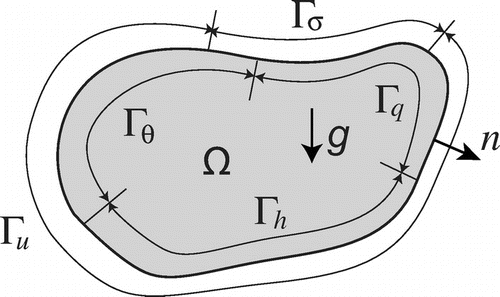
where the boundary , see Figure .
The boundary conditions and initial conditions are:(6)
(6)
(7)
(7)
(8)
(8)
(9)
(9)
(10)
(10)
(11)
(11)
(12)
(12)
(13)
(13)
Here, represents the density,
represents the base temperature,
represents the dynamic viscosity,
, and g represents the acceleration of gravity. Moreover,
represents the coefficient of thermal expansion,
represents the thermal diffusivity,
and
represent the heat flux and the heat transfer coefficient normalized by heat capacity,
represents the external temperature,
represents the initial flow velocity,
represents the initial pressure,
represents the initial temperature,
represents the Kronecker delta. Finally,
represents the known function on the boundary.
The weak forms of the respective governing Equations (Equation4(4)
(4) )–(Equation6
(6)
(6) ) can be expressed with adjoint flow velocity
, adjoint pressure
and adjoint temperature
as follows:
(14)
(14)
(15)
(15)
(16)
(16)
Furthermore, ,
,
, c(w, p),
, l(w),
,
,
,
,
, and
are defined as follows:
(17)
(17)
Here, the superscripts V and H denote terms about the viscosity and heat, the subscripts q and h, hf denote terms about the heat flux and the heat transfer. Tensors described in this paper use the Einstein summation convention and differentiation , while
expresses the time derivative of the function.
The flow velocity u, its adjoint w, and the other variables are considered to be elements of the following functional spaces:(18)
(18)
(19)
(19)
(20)
(20)
(21)
(21)
(22)
(22)
4. Prescribing temperature on a sub-boundary
4.1. Problem formulation
In this section, the problem of minimizing the square integration errors between the actual temperature from time
to
and the target temperature
on sub-boundary
is formulated. We assume
. The domain variation of this natural convection field region
is denoted by
, and the domain
is assumed to vary to reach
. For simplicity, we assume that the sub-boundaries
,
and
are invariable, that is
,
and
for domain variation. The square integration error problem for temperature distribution from time
to
is formulated as follows:
(23)
(23)
where is a coefficient related to the initial domain measure M, and
(24)
(24)
4.2. Shape gradient function
The square integration error problem can be rewritten as a retention problem without any restrictions from the Lagrange multiplier method. In this instance, the Lagrange function is given as follows:
(25)
(25)
where ,
, and
were introduced as Lagrange multiplier functions or the adjoint functions, with respect to the weak forms. The non-negative real constant number
is Lagrange multiplier with respect to the volume constraint. The derivative of L with respect to domain variation is derived using the velocity field (Equation3
(3)
(3) ), as follows, [Citation7,Citation8],
(26)
(26)
Here, represents the derivative with respect to domain variation of the function fixed on the spatial coordinates, and
(27)
(27)
where(28)
(28)
and , and
are determined by the following conditions:
(29)
(29)
(30)
(30)
(31)
(31)
(32)
(32)
(33)
(33)
The derivative of the Lagrange function agrees with the derivative of the evaluation function, establishing the following relationship:(34)
(34)
Since in Equation (Equation28
(28)
(28) ) is a coefficient function of the velocity field
that provides minute variations in the domain,
is referred to as a sensitivity function or shape gradient function. Furthermore, the scalar function G is referred to as the shape gradient density function.
Equation (Equation30(30)
(30) ) is a weak form of the Navier–Stokes equation and the continuity equation. Equation (Equation31
(31)
(31) ) is a weak form of the energy equation in the state equation. Equation (Equation32
(32)
(32) ) is a weak form of the Navier–Stokes equation and continuous state equation for the adjoint problem, Equation (Equation33
(33)
(33) ) is a weak form of the energy equation in the state equation for the adjoint problem, and (Equation34
(34)
(34) ) is a constraint equation related to the Lagrange multiplier
. The traction method can be applied if the shape gradient function can be evaluated by analyzing
, and
based on these equations.
Furthermore, considering the continuity equation for the adjoint equation, and assuming that the flow velocity on the design boundaries satisfies , the shape gradient density function G can be expressed from (Equation29
(29)
(29) ) as
(35)
(35)
where is the shape gradient density function for the square integration errors and
is the shape gradient density function for the constraint conditions.
The same procedure can also be used to derive the adjoint equation and shape gradient function when prescribing the temperature in sub-domain
.
The adjoint equations for the shape identification problem can be expressed as follows:(36)
(36)
(37)
(37)
(38)
(38)
5. Maximizing heat discharge on a sub-boundary
5.1. Problem formulation
The problem of maximizing the discharged heat from time to
on a sub-boundary
is formulated in the same way as in Section 4.1. For simplicity, we assume that the sub-boundaries
,
and
are invariable, that is
,
and
for domain variation. The heat discharge maximization problem from time
to
is formulated as follows:
(39)
(39)
where(40)
(40)
5.2. Shape gradient function
The Lagrange function for this problem is given by the following formula:
(41)
(41)
Assuming that the flow velocity satisfies at the design boundary, the shape gradient density function for the problem is given by (Equation36
(36)
(36) ).
The adjoint flow velocity , adjoint pressure q, adjoint temperature
, and Lagrange multiplier
related to the heat discharge maximization problem are determined by the following adjoint equations:
(42)
(42)
(43)
(43)
6. Solution
6.1. Traction method
The traction method has been proposed for solving the velocity field that indicates domain variation. Domain variation is based on the following governing equation [Citation7]:
(44)
(44)
and(45)
(45)
Here, is a bilinear form indicating the strain energy on a linear elastic body, which is defined by the following equation with respect to the displacement vector function
,
:
(46)
(46)
where is a constant elastic tensor that is positive definite. Equation (Equation44
(44)
(44) ) indicates that the velocity field
is analyzed as a displacement field when the negative shape gradient function
is applied as an external force. The domain variation resulting from the traction method can be derived as a displacement field when the shape gradient function is applied to the pseudo-elasticity problem as an external force.
Furthermore, this analysis is a heat convection field analysis. For simplicity, the elastic tensor is given by
(47)
(47)
Taking account of a bilinear Equation (Equation44(44)
(44) ) and
, the domain variation is expressed as
. We obtain
(48)
(48)
The Lagrange multiplier is determined from
(49)
(49)
Finally, because are given, the domain
is moved into
.
6.2. Analysis procedure
The proposed shape determination analysis can be performed by repeating the following steps:
| Step 1. | Give initial shape. | ||||
| Step 2. | Analyze the flow velocity | ||||
| Step 3. | Stop when the objective functional has converged. | ||||
| Step 4. | Analyze the adjoint flow velocity | ||||
| Step 5. | Calculate the shape gradient density function G based on these results using Equation (Equation36 | ||||
| Step 6. | Calculate the velocity field | ||||
7. Numerical experiments
To verify the proposed method, numerical programs for the above two shape determination problems were developed based on FreeFem++. This section presents simple numerical experiments analyzed using the derived shape gradient function and the traction method to solve the problem of prescribing temperature history at a sub-boundary and the problem of maximizing heat discharge.
7.1. Prescribing temperature on a sub-boundary
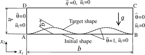
An analysis model was considered similarly to the model presented by Park et al. [Citation13] and shown in Figure . In Figure , the target shape is represented by dotted lines, while the initial shape is represented by solid lines. The boundary conditions of the temperature field were assumed as follows. The lower surface boundary AB was assumed to be the high temperature base boundary and was set to
K. Surfaces DA and BC on the left and right, respectively, were assumed to be low temperature base boundaries
and were set to
=0 K. Surface DC at
was assumed to be a natural boundary, and the thermal insulation condition was set to
. The temperature for the target shape on surface DC was assumed to be the target temperature
in Equation (Equation25
(25)
(25) ). The boundary conditions for the flow field assumed that all surrounding boundaries were wall boundaries set to
.
The initial conditions were set to and
for the entire domain. Internally generated heat was ignored, and the pressure was considered to be unique in order to achieve an average value of 0. The time was set to
and
, while time integration was performed from
s to
s with a time increment of
s.
The prescribed temperature on boundary was considered for the upper surface DC. The design boundary
was considered to be the high temperature base boundary of lower surface AB. The remaining boundaries were set using constraints on the shape variation, specifically low temperature base boundaries DA and BC and thermal insulation boundary DC.
The temperature field , flow field velocity
and pressure p, adjoint temperature
, adjoint flow velocity
and adjoint pressure q, and shape updating analysis (velocity field
) were all performed using FreeFem++ [18,19]. A triangular secondary element was used for
, and
, while a triangular primary element was used for p, q.
Based on the FEM, an analysis was performed using the function ‘convect’ of FreeFem++ on the state equation in the time direction. The function ‘adaptmesh’ of FreeFem++ was used to perform remeshing for shape updates; ‘adaptmesh’ is a function that generates an adaptive mesh for improving solution accuracy of the state variables derived by finite-element analysis. Adaptmesh was used to improve the accuracy of the shape gradient density function G and velocity field . The following physical values were used based on the book [Citation18]: density
= 1.0 kg/m
, dynamic viscosity
Pa s, Prandtl number
, thermal diffusivity
, gravitational acceleration
m/s
downward, base temperature
K, and coefficient of thermal expansion
1/K. The dimensions of the shape were set to
m,
m and
m.
The value of the objective functional at iteration k was denoted by , and convergence was reached when
(50)
(50)
where is a small number.
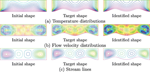
For , a comparison of the initial, identified and target shapes is shown in Figure . The temperature
, flow velocity
, and streamlines at the end time
s for the respective shapes are shown in Figure . From Figure , it was confirmed that the temperature distribution, flow velocity distributions, and streamlines in the identified shape agreed with those in the target shape.
Figure 4. Temperature distributions, flow velocity distributions, and streamlines at time for Park’s problem.
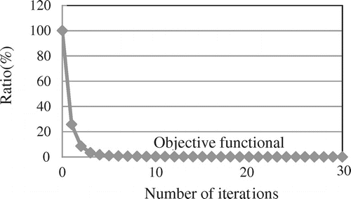
A comparison of the target shape (dotted lines) and the outline of the obtained shape (solid lines) is shown in Figure . The target and identifying shapes are practically identical. Figure shows the iterative history for the objective functional, normalized with initial value.
Figure 8. Mesh and distribution of temperature and streamlines at time 600 for initial shape for heat discharge maximization problem.
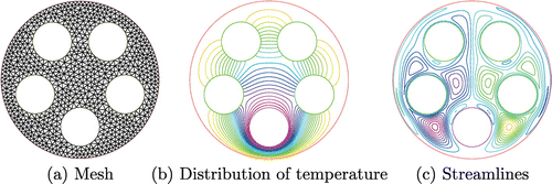
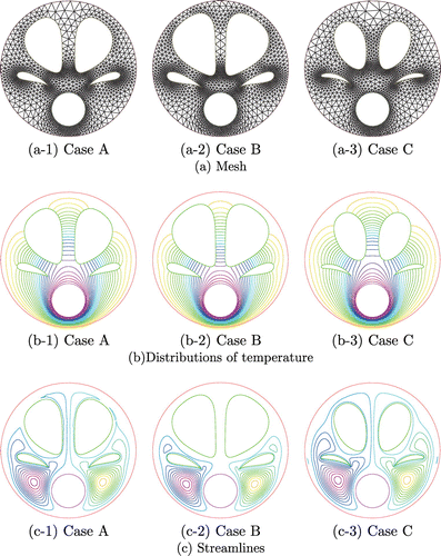
Figure 9. Numerical results: Mesh and distributions of temperature and streamlines at time 600 for optimum shape for heat discharge maximization problem.
These results confirm that the objective functional, which is reduced to practically zero, and the identifying shapes, which are practically identical to the target shapes, can be obtained using the proposed method.
7.2. Maximizing heat discharge on a sub-boundary
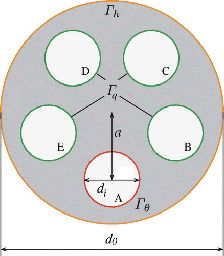
A disc with five holes, as depicted in Figure , was used as an analysis model for the problem of the maximizing heat discharge for an unsteady natural convection field.
The boundary conditions considered hole A on the lower side to be the known temperature boundary and was set to
K. Holes B, C, D and E were considered to be thermal insulation boundaries
and were set to
mK/s. The external boundaries considered
m/s and
K as heat transfer boundaries
. The boundary conditions for the flow field assumed that all surrounding boundaries were wall boundaries set to
= 0. The initial conditions of the entire domain were set to
and
. Internally generated heat was ignored, and the pressure was uniquely set to achieve an average of 0. The time was set to
and
, and time integration was performed from
s to
s with
s time increment. The four hole boundaries B, C, D, and E comprising thermal insulation boundary
were considered to be design boundaries
. Other boundaries were constrained with respect to domain variation in order to analyze the problem of maximizing the heat discharge at the external heat transfer boundary
.
The physical values were the same as those used in the example of Section 7.1, while the dimensions were set to m,
m, and
m. The coefficient
, which restrains the size of the domain, was varied for three values: in Case A,
; in Case B,
; and in Case C,
. For
, the obtained shape for optimization resulted in a sharpened shape along the horizontal direction for hole boundaries B and E, even when the FreeFem++ adaptmesh function was used after each shape update. It was therefore difficult to converge to the heat discharge value from the given initial guess. As a result, the value of
was set to
.
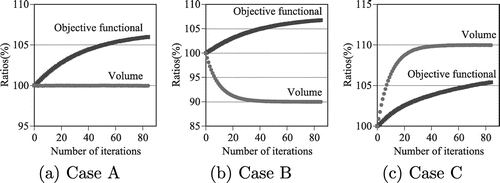
The mesh, temperature, and streamlines of the initial shape at end time s are shown in Figure , with the corresponding numerical results shown for Cases A, B, and C in Figure . The heat discharge, which is the objective functional being sought by shape updates, and domain size changes are shown in Figure . In Figure , the objective functional and the volume are normalized with initial value. The shape of hole boundaries B and E was updated in the horizontal direction in all cases based on the results shown in Figure . The temperature was elevated in the heat transfer boundary near hole boundaries B and E. As a result, the obtained shape had increasing heat discharge on the external heat transfer boundary
. A review of the Case B results reveals that the shape was modified for vertical extension on hole boundaries C and D, where the influence of the heat discharge is relatively low. This resulted in a shape that satisfies the restraining condition
to reduce the size of the domain. Similarly, the shape of boundaries C and D was vertically modified in Case C as well, resulting in a shape that had an increased domain size. The results shown in Figure confirm that, in all cases, the heat discharge increased while satisfying the constraining conditions of the domain size. An improvement of about 5% occurred with respect to the initial shape.
8. Conclusion
This paper proposed a numerical method for two problems: the problem of shape identification for prescribing the temperature history for a sub-boundary in unsteady natural convection fields, and the problem of shape optimization for maximizing heat discharge on a sub-boundary. These problems were formulated, and the shape gradient density functions were derived. The verification of the proposed method was accomplished using simple examples of two-dimensional problems by applying the traction method to the shape gradient distribution functions.
In addition, in this study, we did not consider noise in the input measurement and a corresponding stopping criterion for iterations. Because these are important matters about shape determination of inverse problems, we are going to examine them as future research themes.
Notes
No potential conflict of interest was reported by the authors.
References
- Pironneau O. On optimum profiles in Stokes flow. J Fluid Mech. 1973;59(1):117–128.
- Pironneau O. On optimum design in fluid mechanics. J Fluid Mech. 1974;64(1):97–110.
- Pironneau O. Optimal shape design for elliptic systems. Berlin: Springer-Verlag; 1984.
- Imam MH. Three-dimensional shape optimization. Int J Numer Methods Eng. 1982;18:661–673.
- Jameson A. Optimum aerodynamic design using control theory. In: Hafez M, Oshima K, editors. Computational fluid dynamics review 1995. New York (NY): Wiley; 1995. p. 495–528.
- Mohammadi B, Pironneau O. Applied shape optimization for fluids. New York(NY): Oxford University Press; 2001.
- Azegami H. Solution to domain optimization problems. Trans Japan Soc Mech Eng Ser A. 1994;60:1479–1486. Japanese.
- Azegami H, Shimoda M, Katamine E, et al. A Domain optimization technique for elliptic boundary value problems. In: Hernandez S, Brebbia CA, editors Computer aided optimum design of structures IV. Southampton: Structural optimization, Computational Mechanics Publications; 1995. p. 51–58.
- Azegami H, Kaizu S, Shimoda M, et al. Irregularity of shape optimization problems and an improvement technique. In: Hernandez S, Brebbia CA, editors Computer aided optimum design of structures V. Southampton: Computational Mechanics Publications; 1997. p. 309–326.
- Katamine E, Kiriyama Y, Azegami H. Multi objective shape optimization in forced heat-convection fields. Trans Japan Soc Mech Eng Ser B. 2013;89:2239–2253. Japanese.
- Momose K, Kawano H, Kawahara G. An approach for shape optimization with sensitivity analysis in heat convection fields. Proc Thermal Eng Conf. 2009;:177–178. Japanese
- Park HM, Ku JH. Shape identification for natural convection problems. Commun Numer Methods Eng. 2001;17:871–880.
- Park HM, Shin HJ. Shape identification for natural convection problems using the adjoint variable method. J Comput Phys. 2003;186:198–221.
- Aounallah M, Belkadi M, Adjlout L, et al. Numerical shape optimization of a confined cavity in natural convection regime. Comput Fluids. 2013;75:11–21.
- Yaji K, Yamada T, Kubo S, et al. A topology optimization method for a coupled thermal-fluid problem using level set boundary expressions. Int J Heat Mass Transfer. 2015;81:878–888.
- Alexandersen J, Aage N, Andreasen CS, et al. Topology optimization for natural convection problems. Int J Numer Methods Fluids. 2014;76(10):699–721.
- Haug EJ, Choi KK, Komkov V. Design sensitivity analysis of structural systems. New York (NY): Academic Press; 1986.
- Ootsuka K, Takaishi T. Finite element analysis using mathematical programming language FreeFem++. Tokyo: Kyoritsu; 2014. Japanese.
- Hecht F. New development in FreeFem++. J Numer Math. 2012;20(3–4):251–265.

