
 ?Mathematical formulae have been encoded as MathML and are displayed in this HTML version using MathJax in order to improve their display. Uncheck the box to turn MathJax off. This feature requires Javascript. Click on a formula to zoom.
Abstract
In this work we derive surface integral formulae for the frequency dependent power operator in arbitrary geometries. This operator is combined with layer representations and measured pressure (or normal velocity) near-field holograms to construct a non-negative intensity distribution quantifying the areas of the vibrating structure that produce radiation to the far-field. It is demonstrated that the sound producing regions of the structure are clearly revealed using the derived formulae and that the spatial resolution is limited to a half-wavelength. We validate our methodology using numerically generated data that corresponds to the excitation of an elastic spherical shell by a point force.
1. Introduction
1.1. Overview
By virtue of their interaction with the fluid boundary, vibrating structures emit a sound that often we would like to reduce. The level of the emission from a structure is quantified by the radiated acoustic power, computed from the integral over its vibrating surface of the normal acoustic intensity. The location of unwanted sources of sound on the structure is identified from large values of surface intensity especially when it is not highly bipolar (positive and negative), that is, when there is a minimum circulation of power flow in and out of the structure. Most vibrating structures of interest exhibit a highly bipolar intensity and thus it is very difficult to locate hot spots of radiation in an effort to control the vibrator.
Array measurements that consist of microphones (or velocity probes) sampling the fields simultaneously at a spatially distributed set of points are common in acoustics. Array measurements are ideal for beamforming, very common in the acoustic measurement industry which is often used to locate sources in space. Although intensity arrays also exist providing a direct measurement of the intensity at each sensor location, there are elegant mathematical formulations that allow for an indirect measurement of the intensity based on the distributed measurement of the pressure/velocity fields acquired from arrays with pressure/velocity probes. For example, for separable surfaces of the wave equation (planes, spheres or cylinders), the field has a spectral eigenfunction decomposition that allows the localization of sources on the vibrator. One such method is near-field acoustical holography (NAH) [Citation1]. Similarly this decomposition can be explicitly used to the localization of hot spots by minimizing the bipolar nature of the intensity field. This approach is known as supersonic intensity (SSI) [Citation2,Citation3]. The SSI technique has been used extensively to locate the radiation sources on naval ships with great success.
Although the previous approaches are powerful, they have been developed only for geometries that allow the analytical spectral eigenfunction decomposition. Recently it has been shown that SSI could be formulated in a planar geometry as a spatial convolution with a known kernel [Citation4,Citation5] avoiding the need for Fourier transforms, yielding direct insight into the SSI method due to knowledge of the analytical form of the convolution kernel (first order Bessel function). There have been other methodologies for arbitrarily shaped geometries that use boundary elements methods (BEM) discretizations combined with a spectral cut of the singular value decomposition [Citation6–Citation8]. Although proven efficient in certain conditions, the spectral cut is based on ad-hoc rules. Another approach uses the explicit representation of the impedance matrix to produce a non-negative intensity quantity [Citation9]. There are many promising aspects of this approach, but the calculation of the explicit matrix representation can be computationally expensive. Recently in [Citation10] we introduced an approach based on the calculation of the power operator for the single layer representation, which utilizes spectral cut to estimate the SSI. The ideas of this paper were improved in our recent work [Citation11], where we developed an explicit integral formula of the power operator that produces a non-negative intensity.
In this work we extend the previous theoretical results in [Citation11]. In Section 2 we expand the power operator integral representation for the double and combined layer representation. The corresponding non-negative intensity representation is shown in Section 3 with corresponding reconstructions for numerically generated point sources data. Finally in Section 4 we validate all the non-negative intensity methodologies using data from a spherical elastic shell excited by a point force.
1.2. Integral representations of radiating waves
Assume that represents a complex vibrating structure in a fluid and
is connected. Denote as
the corresponding boundary of
,
a bounded domain that contains
and let
be its corresponding boundary (see Figure ). For a steady-state acoustic wave p its radiating behavior in an homogeneous medium is modeled by the Helmholtz equation
(1)
(1)
where ,
is the wave number,
the angular frequency and c is the speed of sound in the medium.
Figure 1. Setup for exterior radiation problem.
The classical representation of a radiated acoustic wave (known as the Direct formulation) uses the Helmholtz–Kirchhoff integral equation [Citation12](2)
(2)
where denotes the normal velocity. Here we follow the notation of [Citation13], for the single and double layer operators S and K given by
(3)
(3)
and the normal derivative operators and T given by
(4)
(4)
where(5)
(5)
is the free space radiating fundamental solution to the Helmholtz equation. In (Equation3(3)
(3) ) and (Equation4
(4)
(4) )
is the outward unit normal and in (Equation2
(2)
(2) )
is the medium density. As in [Citation13] there are jump relations when
(6)
(6)
where the superscript sign ‘’ is used to denote that
is the limiting value of the sequence of points
.
As an alternative to representation (Equation2(2)
(2) ), we found representations to (Equation1
(1)
(1) ) that use individual layers (known as the indirect formulations) like the single layer representation (see [Citation14–Citation16])
(7)
(7)
or the double layer representation (see [Citation17,Citation18])(8)
(8)
In (Equation7(7)
(7) ) and (Equation8
(8)
(8) ),
is the surface density function. When
is a Dirichlet eigenvalue of the Laplace operator in
then it is known that there is no unique
such that the single layer representation in (Equation7
(7)
(7) ) holds. A similar situation is found for the double layer representation in (Equation8
(8)
(8) ) when for
a Neumann eigenvalue of the Laplace operator in
. This situation is avoided using combined representation [Citation13] (also known as the Burton-Miller representation [Citation19] in the acoustic literature)
(9)
(9)
for a positive constant .
1.3. Radiation theory
The classical structural acoustic theory (see [Citation1,Citation20]) assumes that the radiating sound pressure p results from the interaction between the structure vibration and the normal derivative of the acoustic pressure
. This interaction is modeled by Euler’s equation
(10)
(10)
The acoustic pressure p is given in units and the normal velocity
in
units. The total power (given in units of
) that radiates from the surface
, for the wave p, is given by
(11)
(11)
where the normal intensity
is a power density quantification (with units of ) over the surface of the vibrating structure
.
In this work we are interested in the inverse problem of wave continuation [Citation21] or NAH [Citation22]. For this inverse problem we use acoustic sensors located over the surface which (ideally) is close and conformal to the vibrating structure
. The goal of this problem is to reconstruct the complete acoustic field (pressure, velocity and intensity) at the surface
from the measurements at
. The classical methodology of solution requires that the field p is represented by an integral boundary layer, so the inverse problem is reduced to the reconstruction of the surface density
for the corresponding integral equation over
. Then the corresponding acoustic field at
uses the density
with the corresponding surface layer (and jump relation) (see [Citation16] for more details). The single layer representation (Equation7
(7)
(7) ) uses the resultant density
to obtain the field
(12)
(12)
Similarly the double layer representation uses the resultant density to obtain
(13)
(13)
Finally the combined layer approach use the density to obtain(14)
(14)
Given the layer representation (Equation7(7)
(7) ), (Equation8
(8)
(8) ) or (Equation9
(9)
(9) ) of the acoustic wave p, the radiated power is given by
(15)
(15)
where P is known as the power operator [Citation11]. From this representation, we have the explicit expression for the normal intensity(16)
(16)
The normal intensity shows the distribution of the acoustic energy at the radiating surface. A positive value of the intensity means energy leaving the surface (in direction of the normal), while negative values means energy entering the structure (in opposite direction of the normal).
For the single layer representation (Equation7(7)
(7) ) we denote the power operator in (Equation15
(15)
(15) ) as
and the corresponding intensity
. Similar notations for the representations (Equation8
(8)
(8) ) or (Equation9
(9)
(9) ) for the power operator will be
or
respectively and the intensity as
or
. As explained in [Citation11] the intensity reconstructions from the NAH technique will contain complex combinations of negative and positive values. In Sections 2 and 3 we provide explicit integral representations of
,
,
and a proof that the corresponding operators are positive definite. These results allows to create an expression for the ‘non-negative’ intensity
(17)
(17)
for the power operator P (which can be ,
or
) and the upper script denotes the square root of the operator. We will show that the expression for the non-negative intensity matches total power, providing an expression for the SSI.
2. Power operator representations
2.1. Mathematical preliminaries
A Lipschitz surface , means that
is locally the graph of a Lipschitz function. A surface
is
if is a locally graph of functions where the rth derivative is Lipschitz. We will assume that
is a Lipschitz boundary, which means that
is locally the graph of a Lipschitz function. We will consider only
with connected
. Recall that
denotes the Sobolev space of functions on
whose partial derivatives up to order s are square integrable and
denotes the standard norm in this space. Similarly
denotes the space of functions that are
for every ball B that contains
. We let
be the norm in the space
.
Finally we define the inner product between trace functions and
with .
We will use the following useful results that can be found in the acoustic literature. Assume that is a solution to the Helmholtz Equation (Equation1
(1)
(1) ) with
and Sommerfeld radiation conditions (Equation1
(1)
(1) ). For the following lemmas let
be a bounded domain with Lipchitz boundary. Assume that
contains
. We denote as
the ball with center in the origin and radius
. Similarly
is the boundary of
. For the following result we will utilize the spherical harmonics, which are defined as
(18)
(18)
for and
, where
and
is the associated Legendre function. It is well known that the spherical harmonics form an orthonormal basis at the surface of the unit sphere
, moreover at
where is the Kronecker delta function. The radiating solution p can be represented in
(see [Citation23])
(19)
(19)
where is the spherical Hankel function of the first kind. This representation yields the explicit expression for the power (see [Citation1, Chapter 6])
(20)
(20)
In the remaining section, we will not make the distinction using the superscript ‘+’ when the layers are evaluated at to simplify the notation. The following Lemma follows from [Theorem 7.1,7.2][Citation24]
Lemma 2.1:
For , we have the following mapping properties
(21)
(21)
If is of class
for an integer
, then (Equation21
(21)
(21) ) holds for
.
Notice that S, and T are self-adjoint operators, while . This will be used in the following result
Assume ,
, then we have the operator representation
(22)
(22)
where .
Lemma 2.2:
The representation in (Equation22(22)
(22) ) satisfies the Helmholtz Equation (Equation1
(1)
(1) ) in
. Moreover
and
(23)
(23)
Proof It’s trivial to show that the representation (Equation22(22)
(22) ) solves (Equation1
(1)
(1) ). From [Theorem 7.1][Citation24] we have that
which yields that and the Euler’s equation yields that
Finally we use this relation to obtain (Equation23(23)
(23) ).
Theorem 2.3:
For , the single layer representation (Equation7
(7)
(7) ) with
-pagination yields the power operator
with the operator representation
(24)
(24)
The double layer representation (Equation8(8)
(8) ) with
yields the power operator
with operator representation
(25)
(25)
Given is of class
the combined representation (Equation9
(9)
(9) ) with
yields the power operator
with the operator representation
(26)
(26)
Proof The result for is found in [Citation11]. For
From Lemma 2.1 we obtain that the operators and
map
to
, then (Equation25
(25)
(25) ) follows.
Finally for , Lemma 2.2 yields
From Lemma 2.1 the operators ,
,
, and
map
to
then
which yields (Equation26(26)
(26) ).
Lemma 2.4:
For the double layer representation (Equation8
(8)
(8) ) yields
(27)
(27)
where the power operator is defined as the integral operator
where(28)
(28)
Proof Using the double layer representation (Equation8(8)
(8) ), we can change the order of integration to obtain the relation
Changing variables and the order of integration, we obtain the first equation from (Equation28(28)
(28) ).
Lemma 2.5:
For the combined layer representation (Equation9
(9)
(9) ) yields
(29)
(29)
were the operators and
are defined as integral operators
where(30)
(30)
Proof We proceed as in the previous lemma, so the relations
and
yield (Equation30(30)
(30) ).
2.2. Representation formulas on an infinite medium
For the following theorem we use the result given in Chapter 7 of [Citation25](31)
(31)
where is the spherical bessel function.
The following Theorem can be found in [Citation11].
Theorem 2.6:
The single source representation (Equation7(7)
(7) ) for a density
yields the integral representation of the power operator in (Equation15
(15)
(15) )
(32)
(32)
Theorem 2.7:
The double source representation (Equation8(8)
(8) ) for a density
yields the integral representation of the power operator in (Equation15
(15)
(15) )
(33)
(33)
Proof Assume that is a ball with radius
such that
then [Citation11, Lemma 2.1] and Lemma 2.4 yield that
Set , then notice that
and
then we have the representation
We use these decomposition over the integral representation of in (Equation28
(28)
(28) ) to obtain
and
Since (see [Citation11]) and r can be arbitrarily large, we let
then
Finally we use (Equation31(31)
(31) ) to obtain (Equation33
(33)
(33) ).
Theorem 2.8:
The combined layer representation (Equation9(9)
(9) ) for a density
and any
, yields the integral representation of the power operator in (Equation15
(15)
(15) )
(34)
(34)
Proof As in Theorem 2.7 we have that
Assume that , then notice that
and
then we have the representation
Using the integral representation of in (Equation30
(30)
(30) ), as in the previous theorem, we obtain
Since r is arbitrarily and then
as
. In a similar way we can also prove that
.
Then we have the expression
Finally using the results from previous theorems we can prove formula (Equation34(34)
(34) ).
Notice that(35)
(35)
Since as
then integral kernel formulas in (Equation33
(33)
(33) ), (Equation34
(34)
(34) ) defines a function continuous when
.
The following corollary results from the techniques used to obtain Theorem 2.8
Corollary 2.9:
The Helmholtz–Kirchhoff formula in (Equation2(2)
(2) ) yields the expression for the power
(36)
(36)
Corollary 2.10:
Assume that is of class
. The power operator
is a compact positive definite operator. If k is not a Dirichlet eigenvalue of
then
is strictly positive. The power operator
is a positive definite operator. If k is not a Neumann eigenvalue of
then
is strictly positive. The power operator
is a strictly positive definite operator.
Proof The proof for can be found in [Citation11]. Lemma 2.4 in [Citation11] yields that the power operators
,
are positive definite. When k is not a Neumann eigenvalue, the uniqueness of the double layer representation guarantees that the operator is strictly positive definite. Finally since the combined representation is unique for any
then
is a strictly positive definite operator.
Figure 2. Half space radiation problem.
2.3. Representation formulas on a half-space medium
In the previous subsection we focus our analysis of the power operator in an infinite medium. For many acoustical applications it will be a substantial simplification to assume predefined interface conditions over a medium. Let consider the information of the problem be given over and
then we denote
,
and
(see Figure ).
The boundary layer operators (Equation3(3)
(3) ) and (Equation4
(4)
(4) ) over
are defined by replacing the fundamental solution
by the half-space solution
(37)
(37)
The function is the fundamental solution to the half-space Helmholtz equation with
for sound-soft interface or
sound-hard interface. The sound soft condition is generally used for underwater problems where we assume that the pressure field is 0 at the air-water interface. Similarly the sound hard condition is used when we assume that the object is laying over a wall or hard object where the normal velocity is 0 at the interface.
Theorem 2.11:
The single source representation (Equation7(7)
(7) ) for the half-space
for a density
yields the integral representation of the power operator in (Equation15
(15)
(15) )
(38)
(38)
Proof The proof of this theorem is found in [Citation11].
Theorem 2.12:
The double source representation (Equation8(8)
(8) ) for the half-space
for a density
yields the integral representation of the power operator in (Equation15
(15)
(15) )
(39)
(39)
Proof We proceed as Theorems 2.7 and 2.8, where
for any domain that contains
and have connected
. Assume that
is a ball
for some
. Since
contains
then
and
then we have the Half-space spherical harmonic representations (see [Citation11])
This yields the representation
and the fact that can be arbitrarily large we conclude formula (Equation39
(39)
(39) ).
Similarly we can prove the theorem.
Theorem 2.13:
The representation (Equation9(9)
(9) ) for a density
and any
, yields the integral representation of the power operator in (Equation15
(15)
(15) )
(40)
(40)
3. Numerical methodology
The numerical methodology will require the discretization of the different surface integral equations introduced in the previous sections. We choose the BEM to produce these discretization, since it is the classical accurate numerical methodology in the area of acoustics (see [Citation15,Citation16,Citation26]).
Assume that the pressure measurements are given by over m points over the measurement surface
and define as
the pressure and normal velocity over n points in the vibrating surface
. Similarly we define
the density
in (Equation6
(6)
(6) ), (Equation9
(9)
(9) ) over
. Moreover
is decomposed into triangular elements with three nodes. In this paper (as recommended in [Citation16]), iso-parametric linear functions are selected for interpolating the integral quantity
. Denote as
the BEM discretization of the single layer operator S and double layer operator K in (Equation3
(3)
(3) ) for
. In addition define as
the discretizations of the power operators
in (Equation32
(32)
(32) ), (Equation33
(33)
(33) ).
An evenly distribution of points on the vibrating surface can be used to produce a triangular surface element decomposition. Basic BEM calculations over the resultant surface element decomposition produces integration weights
(see [Citation27]),
such that
The power is approximated directly from the exact pressure and velocity
using
(41)
(41)
where .
Since ,
and
are the discretization of positive definite operators, then we can compute the corresponding numerical eigenvalue decomposition(42)
(42)
where ,
are sets of orthonormal vectors. Here
denote the positive decreasing sequence of eigenvalues. The numerical identification of the supersonic field from pressure measurements in
for the single layer representation (Equation7
(7)
(7) ) is reduced to the solution of
(43)
(43)
for the double layer representation (Equation8(8)
(8) ) is reduced to the solution of
(44)
(44)
and finally for the combined representation (Equation9(9)
(9) )
(45)
(45)
The resultant solutions of (Equation43(43)
(43) )–(Equation45
(45)
(45) ) are given by
then the supersonic density and corresponding non-negative intensity as(46)
(46)
For the following numerical experiments we choose to validate the proposed SSI methodology using smooth surfaces and
. The surfaces of
and
correspond to the surface of spheres centered at the origin, respectively with radius of 1 and 1.05 m. The spherical surfaces are decomposed into 4990 points over 9976 triangles (as shown in Figure 3a of [Citation11]). At
, the maximum diameter between edges of the triangles is 5 cm and in
we keep an identical point distribution.
In all numerical experiments, the measured pressure at a point is generated by the sum of the a combination of monopoles distributed over an interior spherical surface. The analytical formula used to compute the field for each monopole is given by (Equation5
(5)
(5) ). The column vector
contains the exact generated pressure
in
added by the vector
with Gaussian entries and 40 dB signal-to-noise ratio to simulate measurement errors, i.e.
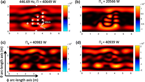
Figure 3. Image of the non-negative intensity using the power operator over the spherical plane ,
at the Dirichlet eigenvalue frequency 171.5 Hz. (a) Exact intensity, non-negative intensity, (b)
, (c)
, and (d)
.

Figure 4. Image of the non-negative intensity using the power operator over the spherical plane ,
at the Dirichlet eigenvalue frequency 446.69 Hz. (a) Exact intensity, non-negative intensity, (b)
, (c)
, and (d)
.
3.1. Dirichlet eigenvalues
We use the conditions of air, with sound speed and density
. The 12 monopoles, used to generate the data, are distributed over a sphere of radius 0.9 m with
locations shown in Figure (a). Between the monopoles, the minimal arc-length distance over the
directions is 60 cm and over the
direction is 40 cm. In addition there is one monopole located at the north pole and one at the south pole.
Table 1. Results from non-negative intensity calculation for Dirichlet eigenvalues.
We apply the proposed numerical supersonic decompositions in (Equation46(46)
(46) ) for frequencies that correspond to
(Dirichlet eigenvalues). As stated in Corollary 2.9 this means that the operator
contains zero eigenvalues and this potentially could affect the accuracy of the intensity
. Table shows the total power
at
numerically calculated from the exact pressure
and normal velocity
as in (Equation41
(41)
(41) ). We denote as
the power that results from the proposed non-negative intensity
, and similarly
,
are the resultant power from the non-negative intensity
,
. The parenthesis in Table show the corresponding relative error between the non-negative intensity and exact power. Notice as expected the non-negative intensity
can underestimate the exact power for some of these problematic frequencies.
Figure (a) shows the exact intensity and Figure (b)–(d) shows the resultant non-negative intensities ,
,
over the spherical plane
,
at 171.5 Hz, and Figure shows these intensities at 446.69 Hz. The resolution of the proposed non-negative intensity images corresponds to half-wavelength resolution (1 and 38 cm respectively). Both the non-negative intensities
and
estimates the correct power but fail to localize sources in 446.69 Hz. Interestingly the images in Figures (b) and (b) shows that the intensity
, even that fails to estimate the correct power, tends to localize the noise sources.
3.2. Neumann eigenvalues
We utilize the same fluid conditions of the previous subsection. We produce data using only 10 monopoles, distributed over a sphere of radius 0.9 m with locations shown in Figure (a). The spacing of monopoles are similar to the previous subsection, without the north pole and one at the south pole positions. We apply the proposed numerical supersonic decomposition in (Equation46
(46)
(46) ) for frequencies that correspond to
(Neumann eigenvalues). As stated in Corollary 2.9 this means that the operator
contains zero eigenvalues and this potentially could affect the accuracy of the intensity
. As in Tables and shows the exact power
and
,
,
are the resultant power from the non-negative intensity
,
,
. Notice that the non-negative intensity
from the double layer representation in (Equation7
(7)
(7) ), can underestimate the exact power for some of these frequencies.
Table 2. Results from non-negative intensity calculation for Neumann eigenvalues.
Figure 5. Image of the non-negative intensity using the power operator over the spherical plane ,
at the Neumann eigenvalue frequency 245.3 Hz. (a) Exact intensity, non-negative intensity, (b)
, (c)
, and (d)
.
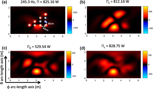
Figure 6. Image of the non-negative intensity using the power operator over the spherical plane ,
at the Neumann eigenvalue frequency 308.25 Hz. (a) Exact intensity, non-negative intensity, (b)
, (c)
, and (d)
.
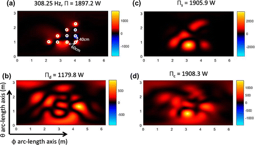
Figure 7. Plot of the multi-frequency acoustical response that results from the proposed point forces. The lower part of the pictures shows the spherical plane ,
view of the acoustical pressure measurement hologram at the surface
for different frequencies.
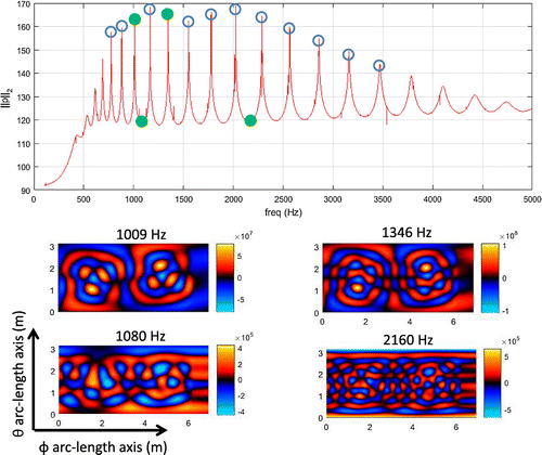
Figure (a) shows the exact intensity and Figure (b)–(d) resultant non-negative intensities ,
,
over the spherical plane
,
at 245.3 Hz, and Figure shows these intensities at 308.25 Hz. The resolution of the proposed non-negative intensity images corresponds to half-wavelength resolution (70 and 56 cm respectively). The non-negative intensity
estimates the correct power and correctly localizes sources (as we found in the numerical experiments of [Citation11]). The intensity images of
and
have a problem localizing the noise sources.
4. Physical experiments
To simulate realistic conditions of a complex structural vibration experiment, we utilize the spherical shell model described in Appendix 1. The resultant field produced by this model have been proven to be realistic for scattering experiments [Citation28,Citation29]. We assume the conditions of underwater thin hollow spherical steel shell, i.e. exterior water medium, interior air medium with steel shell. The dimensions under this conditions are given by the parameters (see Appendix 1) m,
m,
,
,
,
,
and
,
. We set 6 point forces to produce the radiating field. The point forces are located at the north and south pole, and around 4 locations in the
plane shown in Figure (a). Two point forces are separated over the azymuth direction by 60 cm and two are separated over 1 m over the elevation direction.
Figure 8. Elastic shell data. Image of the non-negative intensity using the power operator over the spherical plane ,
at the resonant frequency 1009 Hz. (a) Exact intensity, non-negative intensity, (b)
, (c)
, and (d)
.
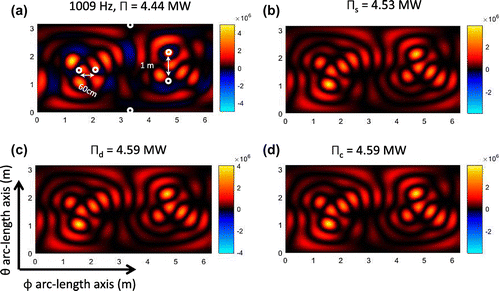
Figure 9. Elastic shell data. Image of the non-negative intensity using the power operator over the spherical plane ,
at the resonant frequency 1346 Hz. (a) Exact intensity, non-negative intensity, (b)
, (c)
, and (d)
.
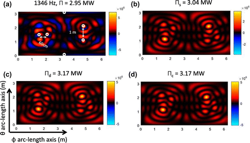
Figure 10. Elastic shell data. Image of the non-negative intensity using the power operator over the spherical plane ,
at the non-resonant frequency 1080 Hz. (a) Exact intensity, non-negative intensity, (b)
, (c)
, and (d)
.
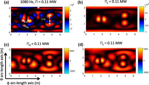
Figure 11. Elastic shell data. Image of the non-negative intensity using the power operator over the spherical plane ,
at the non-resonant frequency 2160 Hz. (a) Exact intensity, non-negative intensity, (b)
, (c)
, and (d)
.
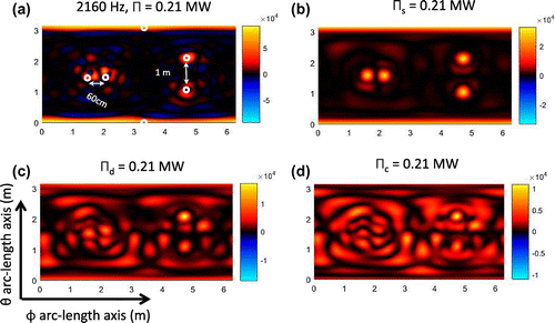
We utilize the same point distribution in the sphere surfaces ,
that we use in the Sections 3.1 and 3.2. This distribution allow us to apply the proposed numerical non-negative intensity methodology up to 4 kHz without violating the wavelength sampling. In Figure we show a typical multi-frequency structural acoustic analysis, where we compute the total pressure response
at each frequency. This allow the noise engineer to identify the resultant acoustic ‘resonances’ which are the frequencies were the structure produces the maximum vibration (peaks of the total pressure response). For our analysis we will process the non-negative intensity reconstructions at the resonance frequencies and analyze two non-resonant frequencies and a frequency that corresponds to the Dirichlet eigenvalue. The lower part of Figure shows the resultant pressure hologram at the surface
for four frequencies. Notice that is hard to identify the location of the point forces just by visual inspection.
Table 3. Results from proposed non-negative intensity calculation for the elastic sphere experiment.
In Table we show the power numerically calculated from the exact pressure
and normal velocity
as in (Equation41
(41)
(41) ), and the corresponding power
that results from the proposed non-negative intensities
,
. The parenthesis in Table show the corresponding relative error between the non-negative intensity power and exact total power. An important result from this table is the fact that all non-negative intensity methods accurately estimate the exact power at all frequencies. Is interesting to point out that even at a problematic frequency 740.5 Hz, like wavenumber
that correspond to a Dirichlet eigenvalue,
correctly estimates the power.
Figures and shows the resultant non-negative intensities ,
,
over the spherical plane
,
at the resonant frequencies 1009 and 1346 Hz. All the non-negative intensities
,
and
estimates the correct power but fail to localize sources at both frequencies. We argue that at resonant frequencies the complete sphere structure is vibrating, so a localization of the sources cannot estimate the total power.
Figures and shows the resultant non-negative intensities ,
,
over the spherical plane
,
at the non-resonant frequencies 1080 and 2160 Hz. As the previous results, all the non-negative intensities estimates the correct power. But at these frequencies the intensity
localize the noise sources better than
,
.
5. Conclusion
Sections 2 and 3 extended the theoretical results of [Citation10,Citation11]. We have shown explicit non-negative intensity formulae from power operators that corresponds to different layer representations. The resultant intensity images ,
,
from numerically generated data demonstrate that the proposed non-negative intensity can be effectively used to estimate the total power in realistic situations. In addition, the non-negative intensity
localizes better the radiation regions for arbitrary surfaces.
Although not discussed in this paper, we can combine all of the previous approaches to identify correctly the radiation regions of the structure. The non-negative intensity provides localized information of the sources, while
can effectively alert the analyst of possible resonant behavior. Also there are still questions about the computation of the non-negative intensity for lower frequencies in which the acoustic half-wavelength is larger than the vibrator surface. Here it is possible to consider the inverse source for single frequencies which has been extensively studied by other authors (see [Citation30–Citation32]).
Additional information
Funding
Notes
No potential conflict of interest was reported by the author.
References
- Williams EG. Fourier acoustics: sound radiation and nearfield acoustical holography. London: Academic Press; 1999.
- Williams EG. Supersonic acoustic intensity. J Acoust Soc Am. 1995 Jan;97(1):121–127.
- Williams EG. Supersonic acoustic intensity on planar sources. J Acoust Soc Am. 1998 Nov;104(5):2845–2850.
- Fernandez-Grande E, Jacobsen F, Leclère Q. Direct formulation of the supersonic acoustic intensity in space domain. J Acoust Soc Am. 2012 Jan;131(1):186–193.
- Williams EG. Convolution formulations for non-negative intensity. J Acoust Soc Am. 2013;134(2):1055–1066.
- Magalhâes M, Tenenbaum R. Supersonic acoustic intensity for arbitrarily shaped sources. Acta Acustica. 2006;92:189–201.
- Tenenbaum R, Magalhâes M. A new technique to identify arbitrarily shaped noise sources. Shock Vibr. 2006;13:219–232.
- Correa C, Tenenbaum R. Useful intensity: a technique to identify radiating regions on arbitrarily shaped surfaces. J Sound Vibr. 2013;332:1567–1584.
- Marburg S, Lösche E, Herwig P, et al. Surface contributions to radiated sound power. J Acoust Soc Am. 2013 Jun;133(6):3700–3705.
- Valdivia NP, Williams EG, Herdic PC. Equivalent sources method for supersonic intensity of arbitrarily shaped geometries. J Sound Vibr. 2015;347:46–62.
- Valdivia NP. Integral formulas for supersonic reconstruction of the acoustic field. Inverse Prob Sci Eng. Fourthcoming 2017. doi:10.1080/17415977.2017.1309399
- Morse PM, Ingard K. Theoretical acoustics. New York (NY): McGraw-Hill Book Company; 1968.
- Colton D, Kress R. Inverse acoustic and electromagnetic scattering theory. 3rd ed., Berlin: Springer; 2013. (Applied mathematical sciences; vol. 93).
- DeLillo TK, Isakov V, Valdivia N, et al. The detection of the source of acoustical noise in two dimensions. SIAM J Appl Math. 2001;61(6):2104–2121.
- DeLillo TK, Isakov V, Valdivia N, et al. The detection of surface vibrations from interior acoustical pressure. Inverse Prob. 2003;19(3):507–524.
- Valdivia N, Williams EG. Implicit methods of solution to integral formulations in boundary element methods based near-field acoustic holography. J Acoust Soc Am. 2004 Sep;116(3):1559–1572.
- Vlahopoulos N, Raveerdra ST. Formulation, implementation and validation of multiple connection and free edge constraints in a indriect boundary element formulation. J Sound Vibr. 1998;201:137–152.
- Schuhmacher A, Hald J, Rasmussen KB, et al. Sound source reconstruction using inverse boundary element calculations. J Acoust Soc Am. 2003;113(1):114–126.
- Burton A, Miller G. The application of integral equation methods to the numerical solution of some exterior boundary-value problems. Proc Roy Soc London Ser A, Math Phys Sci. 1971;323:201–210.
- Fahy F, Gardonio P. Sound and structural vibration: radiation, transmision and response. New York (NY): Elsevier/Academic; 2007.
- Isakov V, Wu SF. On theory and application of the helmholtz equation least squares method in inverse acoustics. Inverse Prob. 2002;18:1147–1159.
- Williams EG, Maynard JD. Holographic imaging without the wavelength resolution limit. Phys Rev Lett. 1980;45:554–557.
- Colton D, Kress R. Integral equation methods in scattering theory. New York (NY): Wiley-Interscience Publication; 1983.
- McLean W. Strongly elliptic systems and boundary integral equations. New York (NY): Cambridge University Press; 2000.
- Stratton JA. Electromagnetic theory. New York (NY): Wiley; 1941. (IEEE press series on electromagnetic wave theory).
- Valdivia N, Williams EG. Krylov subspace iterative methods for boundary element method based near-field acoustic holography. J Acoust Soc Am. 2005 Feb;117(2):711–724.
- Valdivia NP. Numerical methods for near-field acoustic holography over arbitrarily shaped surfaces. In: Monroy FA, editor. Holography: different field of application. Rijeka, Croatia: InTech; 2011.
- Hickling R. Analysis of echoes from solid elastic sphere in water. J Acoust Soc Am. 1962 Oct;34(10):1582–1592.
- Hickling R. Analysis of echoes fwater hollow metallic sphere in water. J Acoust Soc Am. 1964 Jun;36(6):1582–1592.
- Ammari H, Garnier J, Jing W, et al. Mathematical and statistical methods for multistatic imaging. 1st ed., Vol. 2098. Basel: Springer International Publishing; 2013.
- Devaney A, Marengo E, Li M. Inverse source problem in nonhomogeneous background media. SIAM J Appl Math. 2007;67(5):1353–1378.
- Badia AE, Nara T. An inverse source problem for helmholtz’s equation from the cauchy data with a single wave number. Inverse Prob. 2011 Oct;27(10):105001.
- Faran JJ. Sound scattering by solid cylinders and spheres. J Acoust Soc Am. 1951 Jul;23(4):405–418.
- Hampton L, McKinney C. Experimental study of the scattering of acoustic energy from solid metal spheres in water. J Acoust Soc Am. 1961;33(5):664–673.
- Goodman RR, Stern R. Reflection and transmission of sound by elastic spherical shells. J Acoust Soc Am. 1962 Mar;34(3):338–344.
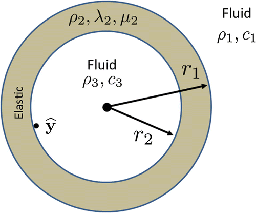
Appendix 1
Spherical shell
We describe the harmonic model of a spherical elastic shell excited by a point force. The analytical formulae of the scattering response correspond to a classical acoustical problem that can be found in [Citation33–Citation35]. It is also important to mention that this formulae has been successfully validated with experimental data [Citation28,Citation29]. The numerical model that we will describe in this section is a generalization of previous works and includes the model of the interaction between a point force and the elastic medium suggested in [Citation1].
Let be a ball centered at the origin with radius
, and the corresponding boundary is denoted as
. We define the shell structure using radius
as in Figure . Outside
we have that the acoustic pressure
solves (Equation1
(1)
(1) ) and the harmonic representation is given by
(A1)
(A1)
where is the spherical Hankel function of the first kind and
. At the shell
we have that the displacements
solve the isotropic elastic medium equation
where are the Lame’s elastic parameters and
the density of the elastic medium. The harmonic representation is given by
(A2)
(A2)
where(A3)
(A3)
Here ,
are respectively the spherical bessel and Neumann functions, and
,
. At the fluid inside
we have
(A4)
(A4)
where is the pressure corresponding to a point force and
the resultant scattered wave
(A5)
(A5)
Here and
represents the force (N).
Figure A1. Elastic Shell model. Interior and Exterior domain are homogeneous acoustic mediums and shell contains elastic properties.
The interaction between acoustic pressure in a fluid and the displacement
in an elastic medium is given by the boundary conditions at
(A6)
(A6)
where
At we encounter the boundary condition
(A7)
(A7)
that models the application of a point force in .
Using boundary conditions (EquationA6(A6)
(A6) ) in
and (EquationA7
(A7)
(A7) ) in
we obtain the matrix systems
(A8)
(A8)
and(A9)
(A9)
where
and
The resultant coefficients of the scattering wave (EquationA1(A1)
(A1) ) are found from the solution of the matrix Equation (EquationA8
(A8)
(A8) ) for each n, m. This normally is done numerically, but a few analytical approximations can be found in [Citation33].