 ?Mathematical formulae have been encoded as MathML and are displayed in this HTML version using MathJax in order to improve their display. Uncheck the box to turn MathJax off. This feature requires Javascript. Click on a formula to zoom.
ABSTRACT
In the slider–crank mechanism whereby output piston force is produced against an input force at crank pin centre, the output force varies rapidly when the crank changes its position. For the applications that require a constant piston pushing force as in feeder mechanisms, a method is needed for identifying the parameters to keep output force at a constant value for any crank angle position. Hence in this study, two methods are shown for a slider–crank mechanism operating in horizontal plane. In the first one, a manual control process to generate a constant piston force and the resulting errors are demonstrated. In the second one, identifying the parameters of a mechanical controller for a readily available slider–crank mechanism in an open force control process and the associated error state are shown. Then, an approach to optimize the results of open force control is explained. Finally, the developed methods are generalized for any orientation of the whole slider–crank mechanism. A user friendly interface is developed to transform all the processes into a computer programme. The effectiveness of the methods are numerically illustrated on examples. The results of these examples show that ±4% deviation from the required output force can be obtained pending on the user’s ability while the optimized open force control process provides a maximum error of ±0.4% without any user intervention during operation.
AMS SUBJECT CLASSIFICATION CODES:
1. Introduction
Slider–crank mechanisms have a wide variety of application areas [Citation1–3]. The best known ones are internal combustion engines in which translational motion is converted into rotational motion, and water pumps and compressors by which rotational motion is transformed into translational motion. Another specific application of this mechanism is feeder systems where stock material is pushed towards processing machine. Hence, the feeder slider–crank mechanism should provide a constant pushing force to overcome opposing machine forces. The simplest and most economical solution to this application is to provide an external input force to the pin of crank–connecting rod joint. However, the piston force (i.e. output force) changes significantly with respect to crank angle when the input force applied is kept constant. Hence, a method is required for developing constant force output irrespective of crank angle.
In the literature, there are studies on the control of various quantities for slider–crank mechanisms. In those studies, position, velocity and force control are presented. For example, different control methods are applied in position control of a slider–crank mechanism as in the case of applications of: Proportional Integral Derivative (PID) control in [Citation4]; fuzzy neural network in [Citation5,6]; fuzzy PID in [Citation7]; genetic algorithms in [Citation8]; and adaptive computed torque technique in [Citation9]. Since there are difficulties in defining PID parameters, Chuang et al. [Citation10] have considered using the experiences of expert engineers in PID control of position of a slider–crank mechanism. In addition to these studies, Lin et al. [Citation11] have made comparison between sliding–mode control and fuzzy neural network methods in position control.
From studies based on velocity control of a slider–crank mechanism, Yan and Chen [Citation12] have developed an inverse algorithm for controlling crank velocity such that a slider–crank mechanism can follow a particular speed trajectory. Method has been applied to deep drawing press at constant speed. Inversely determining the design parameters of slider–crank mechanism for control of both position and velocity in slider–crank mechanism is shown by Akcali and Arioglu [Citation13]. Slider–crank mechanisms are also approached from the stand point of control over the coupler points which are supposed to follow a required curve. In another study [Citation14], the same idea is applied to four–link mechanisms. Control of the motion of two links with respect to a given function is approached from pure kinematic point of view in [Citation15,16].
There are also studies in which dynamic effects together with elastic deflections are considered. For example, Liu [Citation17] has presented the analysis and synthesis of a cam-actuated flexible slider–crank mechanism to obtain a desired output motion at a given design speed and damping ratio. Fung and Shue [Citation18] have shown how to suppress vibration and at the same time control the position of a flexible slider–crank mechanism. Saito et al. [Citation19] have demonstrated how to control the angular speed of a crank using self-tuning control method. Komaito and Furuta [Citation20] have exhibited a work in which they have applied projection method for the control of angular speed of crank by controlling energy. Kao et al. [Citation21] have implemented particle swarm optimization technique together with self-tuning PID method to slider–crank control problem.
Force control studies on slider–crank mechanisms generally focus upon dynamic effects. For example, Fung and Chang [Citation22] have used sliding mode control method for path generation of a slider–crank mechanism under the conditions of predefined resistance forces to estimate controlling torque input values. In the available literature, there is no study providing an affective and economical solution developed for obtaining a constant pushing force on the piston of slider–crank mechanism under static conditions, irrespective of crank angle.
In this study, two methods are presented for identifying the mechanical and operational parameters in the control of the piston output force for a readily available slider–crank mechanism used as a feeder system in the horizontal plane. Firstly, an easy-to-apply manual control process and the resulting error state have been shown. Secondly, identification of a spring coefficient (that can be considered as a mechanical controller) through synthesis to make the force independent of crank positions is explained and the related error state is displayed. Application of the methods are generalized for any orientation of the whole slider–crank mechanism. A computer programme involving the design of the mechanical controller is prepared to facilitate the use of the control method. The methods are illustrated on numerical examples. The validation of the methods are carried out in SolidWorks simulations.
2. Method
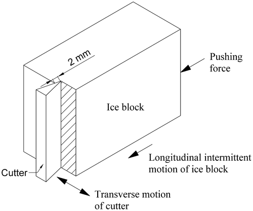
In this paper, ice feeder in an ice cutting machine developed at the Department of Mechanical Engineering in Çukurova University [Citation1] has been considered. The ice cutter blade moves transversely (Figure ) and feeder keeps the ice block under static equilibrium such that during cutting process the ice block and feeder do not move for obtaining the same level of shredded ice particles. Hence, the ice block and the piston of the feeder has an intermittent motion (i.e. 2 mm [Citation1]) in between each cutting phase. Since the motion distance is so small and the feeder mechanism with ice block do not move during the cutting process, the investigation of pushing forces in feeder slider–crank mechanism can be considered under static conditions.
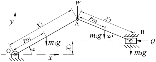
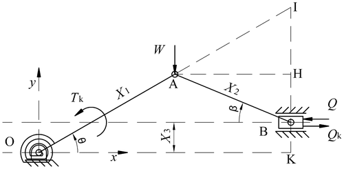
The feeder slider–crank mechanism under consideration is shown in Figure . In this system, stock material placed in front of the piston is fed to production system but, a reaction force Q is developed against the stock material by the production system. Hence, feeding system should push the stock material with sufficient force to overcome the reaction force (Q). The dimensions of the mechanism of interest are crank and connecting rod lengths (X 1 and X 2, respectively) and eccentricity between the crank centre and piston line of action (X 3). The centres of gravity of crank and connecting rod are away from points O and A by r G1 and r G2, respectively. The masses of crank, connecting rod and piston are represented by m 1, m 2 and m 3, respectively. The variables are crank angle θ and connecting rod angle β, with corresponding sign conventions (Figure ).
The requirement for the generation of a pushing feeding force Q can be simply met by applying an external input force W to the crank–connecting rod joint (point A). However, the problem is that pushing force Q changes rapidly under the effect of W, by the position (θ) of crank. In order to see this situation, Virtual Work Method will be applied to get the relationship between Q and W. To apply this method, link weights and the trajectories for the corresponding centre of gravity points have been taken into account, as well.
It is always advantageous to transform a continuous system into a lumped mass problem in the direction of reducing the number of terms by taking into account fewer geometric constraints in applying Virtual Work method. Thus, in order to account for gravitational effects of several masses these effects are reduced to two points: one point moving on a circular path and the other point moving on a recti-linear path. However, the centre of gravity of the connecting rod depends very much on the dimensions of the mechanism and this is not a constant geometric constraint. On the other hand, while applying Virtual Work method on the slider–crank mechanism the fact that displacements of crank and slider are non-linearly correlated makes it necessary to apply the Virtual Work method instantly by simply transforming it into a Virtual Power method.
The weight lumping process can be achieved by finding the statically equivalent mass systems [Citation23] both for crank and connecting rod. The crank mass (m
1) can be replaced by a statically equivalent system lumped at points A () and O (
). The effect of crank weight at points A and O can be expressed as:
(1)
(1)
(2)
(2)
Similarly, the connecting rod mass (m
2) can be replaced by a statically equivalent system lumped at points A () and B (
). Hence, the effect of connecting rod weight at points A and B can be expressed by means of the following relationships:
(3)
(3)
(4)
(4)
Resultantly, the masses can be considered as lumped at points A and B in the system as follows:(5)
(5)
(6)
(6)
whereas the lumped mass at point O (m
O) is defined by Equation (Equation2(2)
(2) ).
The virtual work (ΔW) in the slider–crank mechanism resulting from relevant incremental displacements and forces as well as weight effects of the lumped masses become the following by noting that the displacement at the crank centre (Δs
O) is zero and, accordingly, if Δs
A and Δs
B represent small displacements at the crank (A) and piston (B) points, respectively:(7)
(7)
In Equation (Equation7(7)
(7) ), the last two terms reduce to zero since the first one has zero displacement and the second one has perpendicular components to each other. Dividing the remaining terms in ΔW work by Δt time and taking the limit of it as Δt goes to zero lead to the following scalar equation:
(8)
(8)
(9)
(9)
In Equation (Equation8(8)
(8) ), V
A
and V
B
represent instantaneous velocities of points A and B, respectively, corresponding to angular crank position θ.
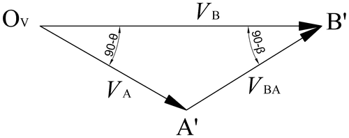
On the other hand, from velocity diagram in Figure , the following can be written by applying Sine Law:(10)
(10)
If Equation (Equation10(10)
(10) ) is substituted into Equation (Equation8
(8)
(8) ) and some algebraic operation is done the following results:
(11)
(11)
where angle β (Figure ) is calculated from the following:(12)
(12)
It is understood from the above equations that piston pushing force Q under the effect of external force W′ changes very rapidly with respect to crank angle θ. Based on kinematics and force relationships, two approaches can be considered in the most economical way for identifying input parameters to hold the piston pushing force at a desired value with an acceptable error no matter what the crank position might be.
2.1. FIRST approach: manual control
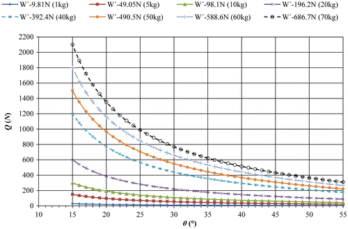
Manual control method is the most suitable solution to this problem since feeding is realized under static conditions. The main question to be asked in the development of this method is that for any crank position θ what external input force value W should be applied to the joint of crank–connecting rod such that a particular desired constant value of output piston pushing force Q in the crank operation interval can be obtained. For that purpose, variation of pushing force Q vs. crank angle θ should be analysed in response to constant input force W′ (i.e. external force and lumped mass effect) applied at point A in the system of Figure . This relationship can be obtained from Equation (Equation11(11)
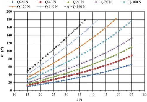
(11) ). If this relationship is drawn graphically (Figure ) it will be seen that as angle θ gets smaller the output pushing force Q to feed stock material to the system becomes larger. In Figure , variation of pushing force Q with respect to angle θ is shown for several constant input force values from 9.81 N (1 kg) to 686.7 N (70 kg). It is evident from these graphs that manual control can be applied for obtaining a constant pushing force Q by decreasing input force W′ as crank angle θ decreases. In order to present this explicitly, variation of W′ with respect to angle θ is also shown (Figure ) for different constant pushing force values from 20 to 160 N. It is clearly seen from the figure that in order to obtain a constant pushing force Q value selected on Figure , input force W′ has to be lowered as crank rotates in the clockwise direction. Therefore, based on the W′–Q–θ relationships on the figure, input W forces can be identified for obtaining any desired piston pushing force Q with respect to the corresponding crank positions. It will later be shown on a numerical example under what error level the indicated problem is solved. It is clear that solution has been found by simply reversing the roles of input–output forces.
2.2. Second approach: mechanical controller design
The manual control method requires a person to work continuously on the machine. At the same time, with a reasonable amount of effort exercised by the human operator, it is not possible to obtain sufficiently accurate piston pushing force. For these basic reasons, cost of production is highered and standard of quality is lowered. Hence, other feasible control methods, in this context an economical mechanical controller design, are required to regulate the pushing force on the piston of slider–crank feeding mechanism with more precision.
The most economical solution that can be proposed to satisfy that condition is to develop a controller that simply consists of a spring. By this way, an increasing opposite force on the piston can be obtained as the spring deviates from the neutral position. Three different points (points O, A and B) on the system (Figure ) have been considered for that purpose. However, the analysis carried out has shown that the only feasible solution is obtained if spiral or a rotational spring is assembled at point O. On the schematically shown system in Figure , a constant net pushing force is developed by balancing the increasing pushing force caused by constant input force W′. There are two forces shown on the piston: force Q represents the pushing force resisting to the constant input force W′, whereas force Q k represents the force resisting to the spring.
The relation between the input force W′ applied at point A and the pushing force Q developed on piston was found out as in Equation (Equation11(11)
(11) ). Torque T
k
generated on crank due to the spring placed at point O can be calculated by the following:
(13)
(13)
In this equation, k, and θ represent spring constant, angle of spring neutral position and instantaneous crank angle, respectively.
The relation between torque due to spring and reaction force on piston (Figure ) can be defined as in Equation (Equation14(14)
(14) ) by applying Virtual Work Method.
(14)
(14)
In this equation, Δθ
2 and Δs
B
represent incremental angular and linear displacements of crank and piston, respectively. If Equation (Equation14(14)
(14) ) is divided by Δt and limit is taken as Δt goes to zero, the reaction force on piston caused by spring can be calculated as shown below:
(15)
(15)
In Equation (Equation15(15)
(15) ), w
2 represents angular velocity of crank. The ratio of w
2/V
B
in Equation (Equation15
(15)
(15) ) can be calculated from the relation of the instantaneous rotation centre I of connecting rod (Figure ), as given below:
(16)
(16)
The reaction force on piston caused by spring can be found by substituting Equation (Equation16(16)
(16) ) in Equation (Equation15
(15)
(15) ):
(17)
(17)
The net force on piston can be calculated by superposing the pushing force caused by applied input force W′ and the reaction force caused by spring, as shown below:(18)
(18)
(19)
(19)
Three equations are needed to estimate the values of three parameters, which are spring constant (k), angle of spring neutral position () and net force on piston (Q
net) in Equation (Equation19
(19)
(19) ). Hence, three crank angles (θ
0, θ
1, θ
2) are selected corresponding to error–free Q
net value (
) in the operation interval of interest. Net piston pushing forces (
, i = 0, 1, 2) against input force W′ are written at the selected crank position angles (θ
i
, i = 0, 1, 2):
(20)
(20)
The conditions for which pushing force deviates with zero error from the desired value () at three positions can be expressed as follows:
(21)
(21)
(22)
(22)
Equations (Equation21(21)
(21) ) and (Equation22
(22)
(22) ) can be simplified as:
(23)
(23)
Here;(24)
(24)
(25)
(25)
(26)
(26)
(27)
(27)
If Equation set of (23) is solved for and k, which are the inverse design parameters of the controller, the following results are found:
(28)
(28)
(29)
(29)
Pushing force corresponding to any input force W′ can be found out by substituting k and
calculated by Equation (Equation28
(28)
(28) ) and (Equation29
(29)
(29) ) into either Equation (21) or (22).
Open control system is finalized with block diagram drawn in Figure in connection with the controller design explained above, where the dashed lines signify the controller and (θ) represents disturbance.
3. Equal error distribution method
A method referred to as ‘equal error distribution method’ will be shown to optimize the results of the control process presented in Section 2.2. In order to achieve optimization, error per cent is defined first as follows:(30)
(30)
Here, Q
net and symbolize actual and desirable constant piston pushing forces, respectively.
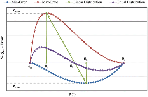
If optimization is desired to be carried out in an interval whose end points are well-defined it can be assumed that θ 2 and θ 0 (i.e. the relevant crank positions where error is supposed to be zero) are set equal to the beginning and end values of the interval, respectively. The intermediate angle θ 1 has a direct effect on the variation of Q net value. As shown in Figure , if θ 1 is selected very close to θ 2 the change in Q net will have the absolute maximum error above the horizontal axis on the graph named as ‘maximum error curve’. On the other hand, if θ 1 is selected very close to θ 0 the change in Q net will have the absolute maximum error below the horizontal axis on the graph named as ‘minimum error curve’. Therefore, a method for selection of angle θ 1 is required for users to limit Q net in ± equal error value through the operation interval of crank arm. For this purpose, the subsequent steps are followed in the calculation procedure to lead to the method called equal error distribution method, which is supposed to yield Q net error curve in the relevant working interval in which absolute maximum and minimum deviations are almost equal.
| (1) | Set θ 2 and θ 0 to beginning and end of operation interval and then select θ 1 as (θ 2 – 0.1°). | ||||
| (2) | Apply the open control procedure as explained above in ‘maximum error curve’. | ||||
| (3) | Determine e max value and the corresponding crank angle θ a from the ‘maximum error curve’. | ||||
| (4) | Now, select θ 1 as (θ 0 + 0.1°). | ||||
| (5) | Apply the open control procedure as explained above in ‘minimum error curve’. | ||||
| (6) | Determine e min value and the corresponding crank angle θ b from the ‘minimum error curve’. | ||||
| (7) | Calculate the new value of the intermediate angle θ 1 with the following formula: | ||||
(31)
(31)
| (8) | Calculate Q net values as a function of crank angle and plot it. | ||||
The plot is supposed to look like the one shown in Figure .
4. Calculation of input force W for desired pushing force Q net on piston
Control process explained in Section 2.2 is based on open control process which does not have any instability issues and generates the most economical solutions. In these types of systems, there is an input value corresponding to a desired output value. Since in control processes, input is the desired output by definition, this process results in an effective input–output calibration. Therefore, the control method explained above is equivalent to per se finding a suitable calibration constant. In that case, the following steps can be followed for finding input force W required to be applied to the slider–crank joint in order to obtain desired force Q net on the piston of a slider–crank mechanism.
| (1) | Dimensions of slider–crank mechanism (X 1, X 2, X 3) are entered. | ||||
| (2) | The mass properties (m 1, m 2, m 3, r G1, r G2) of links are entered. | ||||
| (3) | θ 0, θ 1, θ 2 in the operation interval of crank and a dummy input force W are selected. | ||||
| (4) | β
i
, i = 0,1,2 is calculated for each θ
i
, i = 0,1,2 by Equation (Equation12 | ||||
| (5) | a
0i
, b
0i
, C
0i
, W
0i
, i = 1,2 are calculated by substituting the results from the 4th step into Equations (Equation24 | ||||
| (6) | Firstly, k and | ||||
| (7) | Calibration constants | ||||
| (8) | Required effective input force to be applied ( | ||||
(32)
(32)
(33)
(33)
| (9) | Then, the exact input force (W) can be calculated by Equation (Equation9 | ||||
5. Implications and generalizations of the application
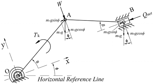
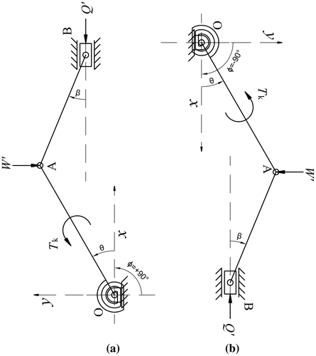
The techniques discussed so far in this paper have focused upon a slider–crank mechanism with piston moving horizontally. In this case, gravitational effects due to weights of the moving links are easily combined with the external input forces (W′) and output piston force (Q net), which are always perpendicular to each other. However, it is possible to generalize the problem to a case in which the piston moves at an angle φ with respect to the horizontal axis as shown in Figure .
In the system of Figure , externally applied constant input force at point A is perpendicular to the piston motion axis. Hence, the gravity effects of the lumped masses at points A and B can be decomposed into two components that are perpendicular and parallel to the piston motion axis. The relation between the net piston pushing force and all other acting forces can be defined by applying Virtual Work Method as follows:(34)
(34)
By defining W″ and as shown below and carrying out algebraic manipulations on Equation (Equation34
(34)
(34) ) the following will be obtained:
(35)
(35)
(36)
(36)
(37)
(37)
It should be noted that Q
net in Equation (Equation36(36)
(36) ) is the net resistive force applied externally on the piston. Then,
can be solved from Equation (Equation37
(37)
(37) ) as follows:
(38)
(38)
Equation (Equation38(38)
(38) ) can now be simplified by defining new terms such as
and W
A
, as given below:
(39)
(39)
(40)
(40)
(41)
(41)
Since the structures of Equations (Equation41(41)
(41) ) and (Equation20
(20)
(20) ) are similar, the same solution procedure is applicable to estimate the values of three parameters, which are spring constant (k), angle of spring neutral position (
) and net force on piston (
) in Equation (Equation41
(41)
(41) ). To that end, constant force conditions of discrete crank angles (θ
i
, i = 0, 1, 2) are written as follows:
(42)
(42)
(43)
(43)
(44)
(44)
Identification of inverse design parameters (k, and
) can be determined from the following equations:
(45)
(45)
(46)
(46)
(47)
(47)
(48)
(48)
The error of in the operation interval of crank can be equally distributed by following the same procedure given in Section 3 – ‘The Equal Error Distribution Method’. If input force
to be applied to the slider–crank joint has to be calculated such that a desired force
on the piston of a slider–crank mechanism is obtained, the same procedure can be followed as shown in Section 4 – ‘Calculation of Input Force W for Desired Pushing Force Q
net on Piston’. Instead of Equations (Equation32
(32)
(32) ) and (Equation33
(33)
(33) ), the following two equations are utilized for calculating the required input force
and k
desired:
(49)
(49)
(50)
(50)
In Equation (Equation49(49)
(49) ),
should be calculated for the desired output piston pushing force by Equation (Equation36
(36)
(36) ). Then, the exact input force (W) can be calculated by Equations (Equation35
(35)
(35) ), (Equation39
(39)
(39) ) and (Equation40
(40)
(40) ).
6. Development of user interface
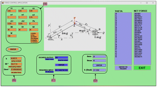
Performing effective computations is made possible by computer programs, which are commensurate with the idea of optimization. A user interface, in the background of which the explained algorithms are transformed into suitable computer programs written in the Visual Basic language, is developed and shown in Figure .
The developed user interface is very helpful for using a readily available slider–crank mechanism as a feeder. Using the interface, the parameters such as spring constant, spring neutral position and external input force required for obtaining a particular output piston pushing force can be easily and directly calculated, instead of designing and manufacturing a new slider–crank mechanism based on the requirements.
In order to utilize the user interface, dimensions and mass properties of slider–crank mechanism (X
1, X
2, X
3, m
1, m
2, m
3, r
G1 and r
G2) as well as required parameters of crank angle (θ
0, θ
1, θ
2) and a dummy input force W value are entered into the section shown by box (A) in the figure. By clicking ‘ENTER’ button, corresponding k, and
values are calculated automatically and displayed in box (B). The desired output force value (Q
net) that resists to the piston externally is entered into the related section in box (C) followed by ‘ENTER’ button again. The required input force W to be applied at point A is calculated and shown directly in ‘REQUIRED INPUT’ box. Following the determination of θ
min and θ
max values (the smallest and largest crank angle) for the calculation of Q
net values, they are entered in box (D) and ‘ENTER’ button is clicked. The new spring constant (k) calculated for the desired output force is shown as ‘k (final)’. Q
net values are calculated for each 1° increment in crank angle and listed on the right hand side under the titles ‘THETA’ (θ) and ‘NET FORCE’ (Q
net). If it is desired to be written in a ‘text’ file ‘ENTER TO FOLDER’ button should be clicked. The related data are recorded in two separate files. For comparison purposes, it is also possible to obtain the change in Q
net value corresponding to the external weight force, without any spring, for the defined crank angle interval which can be achieved by simply entering ‘0’ for k in box (B) and, clicking ‘ENTER’ button.
7. Numerical examples
In this section, the effectiveness of the developed methods is shown on a slider–crank feeder mechanism for which crank angle operates from 45° to 20° with the following dimensions (X
1 = 0.45 m, X
2 = 0.45 m and X
3 = 0.09 m) and masses (m
1 = m
2 = 1 kg and m
3 = 0.76 kg) to generate 300 N piston force. All components are assumed as homogeneous and constant cross-section such that centre of gravity is coincident with centre of symmetry for each component. Using Equations (Equation1(1)
(1) ), (Equation3
(3)
(3) ) and (Equation5
(5)
(5) ), lumped mass at point A can be calculated as 1 kg. In a similar fashion, the lumped mass at point B can be calculated as 1.26 kg.
7.1. Case of manual control
The application of external input force W for the system of Figure can be provided by the weight of constant mass blocks since it is readily available and economical. The required input weight values for each crank angle position as the crank rotates from 45° to 20° are calculated by Equation (Equation11(11)
(11) ) in units of kg and listed in Table . The smallest unit mass value is selected as 0.5 kg for practical applications. Hence, each calculated weight (i.e. mass) value is rounded to the next higher interval unit and the rounded values are shown in the last column (W′–input) of Table . It should be also reminded that W′–input values in Table includes 1 kg lumped mass at point A. Hence, the required input mass for each crank angle is 1 kg less than the tabulated data.
Table 1. W–input values for manual control process.
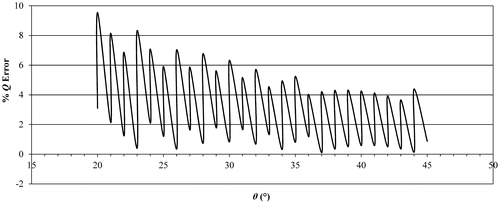
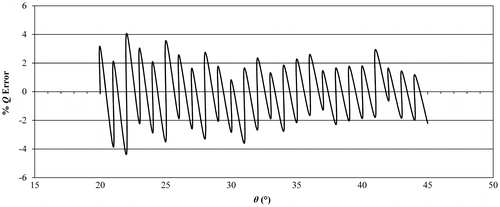
The mass reduction required for crank rotation in clockwise direction from any particular angle to the next small one would easily be obtained from Table . The deviation of the piston force from 300 N vs. crank angle is shown by the plot associated with the error percentage (Q Error %) in Figure . From Figure , it is seen that the variation of the pushing force (maximum – minimum) is less than 10%. Even though this error can be viewed as allowable variation within ±%5 limiting values, the average value of Q net has been offset to 310 N. Hence, it should be better to choose input force W′ to generate ±%5 of Q net values for obtaining desired pushing force values on average. Therefore, the previous calculations are re-performed to keep Q net above 285 N. The resulting new error percentage (Q Error %) graph for this case presented in Figure proves that the average Q net value is centred at the desired value and that distribution of error is also improved. It should be also noted that the better results are achievable by either reducing the unit mass size or crank angle increment value, or both.
7.2. Case with controller design
A spring is utilized as a controller as discussed in Section 2.2. Within this context, an arbitrary weight W of 100 N is assumed as the load to be applied at the crank-connecting rod joint. For angle θ 1, five different values are selected as 25°; 30°; 32.5°; 35° and 40°. These crank angle values are shown in Table . The values of W, θ 0 and θ 2 are to be kept same for the example under consideration and the only parameter subject to change is angle θ 1. Thus, naming of the parameter set will be based on θ 1 value in Table .
Table 2. The parameters used in the application of a controller.
The parameters in each row in Table are entered into the user interface (Figure – Box A) so that input design parameters of spring constant (k), angle of spring neutral position () and net error-free pushing force (
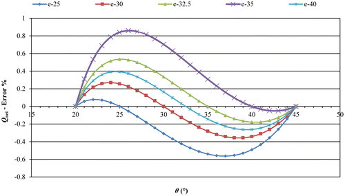
) for each set are determined (Figure – Box B) and collected in Table . The plot of net pushing forces on the piston vs. crank angle for five different conditions are displayed in Figure . Variation of per cent error in the net pushing force with crank angle for selected five different springs is also given in Figure . As is evident from these plots, if angle θ
1 is selected closer to start position (θ
2 = 45°) the maximum error value is less than +1%. If angle θ
1 is selected closer to end position (θ
0 = 20°) the absolute maximum error value below x–axis is around 0.6%. However, if angle θ
1 is selected around mid-point of operation interval the maximum error value stays around less than 0.4% as well as in an evenly distributed form.
Table 3. The parameters calculated in control application.
Figure 13. Variation of net pushing forces developed by a constant 100 N load and five different springs in the operation interval.
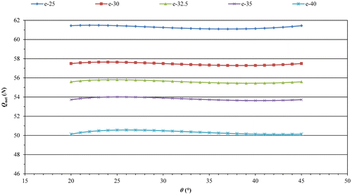
Figure 14. Variation of per cent error in the net pushing force developed by a constant 100 N load and five different springs in the operation interval.
Even though the application of a spring controller has fixed the net piston pushing force over the operating interval, the obtained force values range approximately from 50 to 58 N. However, the desired pushing force on the piston is 300 N. Hence, the input force to be applied to the joint of crank arm and connecting rod has to be found out. Based on ‘e–30’ parameters in Table , the values determined for an arbitrary load of 100 N are adopted to yield the desirable pushing force of 300 N in accordance with the algorithm in Section 4. Then, the required load (W) and spring constant (k desired) obtained as 563.14 and 337.40 N.m/rad, respectively from the user interface (Figure ).
In the next step, ‘Equal Error Distribution Method’ should be applied to calculate the value of θ
1 such that the error on piston pushing force deviating from 300 N desired value is evenly distributed. In the optimization phase of this design (e–30), e
max and e
min curves are obtained by choosing θ
1 values as listed in Table . From these curves (θ
a, e
max) and (θ
b, e
min) parameters are collected in Table . By substituting these values into Equation (Equation31(31)
(31) ), optimized θ
1 value is calculated as 32.51°. Q
net values are re-calculated in the operation interval for this new case and all three curves are shown in Figure . It is evident from the figure that error is constrained in ±0.4% band using Equal Error Distribution Method.
Table 4. The equal error parameters.
Figure 15. Angle θ 1 calculated using Equal Error Distribution Method and the resulted Q net values.
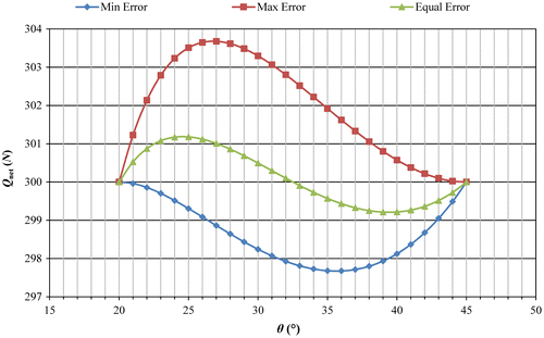
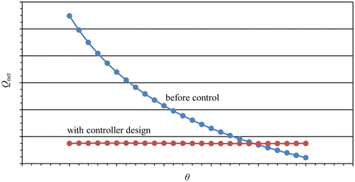
If the results of the piston force before and after the application of the optimum controller design are compared, as generated in Figure , it will be seen that the effect produced by the controller over the control of the pushing force is predominant.
7.3. Case with inclination and controller design
In order to show the general case, two different cases are considered where the slider–crank mechanism is rotated +90° and −90° with respect to the horizontal axis as shown in Figure , respectively. All the dimensions, operating parameters and mass values are the same with the previous cases. For the controller design, e – 30 parameters are chosen from Table . It should be noted that when the inclination angle is selected as 0° the same values are obtained as in Table . By following the procedures discussed in Section 5 – ‘Implications and Generalizations of The Application’ the spring constant (k), spring neutral position () and net force with zero error (
) would be found from the user interface as listed in Table for both cases. Since the desired output piston force is 300 N, W
required and k
desired values are calculated by Equations (Equation49
(49)
(49) ) and (Equation50
(50)
(50) ) as tabulated in Table .
Table 5. Calculated values for the general case applications.
8. Validation and simulation
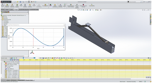
The developed methods are validated in SolidWorks simulation tool. Hence, a slider crank mechanism is modelled (Figure ) with the specifications given in Section 7 – ‘Numerical Examples’. Then the static mode is used for recording the piston pushing forces with the given specifications for e–30 set listed in Table and Table . The external input force W is applied to the pin of the crank – connecting rod. Firstly, crank angle is set to the operation angle and a fixed stop is placed in front of the piston. Then, a moment is applied to the crank calculated from the spring specifications. Once W is applied to the pin of the crank – connecting rod, the reaction force on the piston or the fixed stop is recorded. This process is repeated for every crank angle starting from 45° to 20°. The results of this approach and the user interface are compared in Figure .
Figure 19. Comparison of Q net values obtained by SolidWorks simulations and the developed user interface.
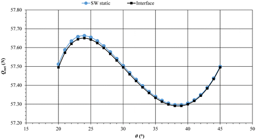
From Figure , it can be seen that the results of SolidWorks static simulation and the developed interface are always coincident which validates the developed method. Very small and insignificant differences of Q net values (0.03% error) at around 20° crank angle are mainly due to number of significant digits used in SolidWorks and the developed interface.
9. Conclusion
In this study, two different solutions that are easy to apply and economical are presented for identifying input parameters of a slider–crank mechanism, which is used as a feeder under static conditions, such that the piston pushing force can be held at a desired constant value. Open control systems, which are free of instability problems, have been preferred. Solutions that deviate from desired values with the least error are presented based on manual control and on the use of optimum controller. Instead of traditional control approach mostly founded on design by analysis, design by synthesis approach is followed for the development of controller. Potential effects for decreasing error percentages in significant amounts are shown with suitable strategies in the presented methods. The method shown here can be implemented to any machine containing slider–crank as the basic mechanism in any orientation, supposed to produce not only uniform slider forces but also uniform speeds in intervals of interest.
Disclosure statement
No potential conflict of interest was reported by the authors.
References
- Erdil, AH . Ice grating machine. MSc Thesis, Çukurova University, Institute of Natural and Applied Sciences, Adana; 1998.
- Vinogradov O . Fundamentals of kinematics and dynamics of machines and mechanisms. 1st ed. Boca Raton (FL): CRC Press; 2000.10.1201/9781420042337
- Myszka D . Machines and mechanisms, applied kinematic analysis. 4th ed. Upper Saddle River (NJ): Prentice Hall; 2012.
- Ahmad F , Hitam AL , Hudha K , Jamaluddin H . Position tracking of slider crank mechanism using PID controller optimized by Ziegler Nichol’s method. J Mech Eng Technol. 2011;3:27–41.
- Lin FJ , Wai RJ . Sliding–mode–controlled slider–crank mechanism with fuzzy neural network. IEEE Trans Ind Electron. 2001;48:60–70. doi:10.1109/41.904553.
- Lin FJ , Fung RF , Lin HH , et al . A supervisory fuzzy neural network controller for slider–crank mechanism. Proc 1999 IEEE Int Conf Control Appl. 1999;2:1710–1715. doi: 10.1109/CCA.1999.801229
- Lee CD , Chuang CW , Kao CC . Apply fuzzy PID rule to PDA based control of position control of slider crank mechanisms. IEEE Conference on Cybernetics and Intelligent Systems; 2004 Dec 1–3; Singapore. 2004. 1, p. 508–513. doi: 10.1109/ICCIS.2004.1460467
- Faraji H , Farzadpour F . Intelligent position control of slider–crank mechanism in the ship’s propeller. 3rd Joint Conference of AI & Robotics and 5th RoboCup Iran Open International Symposium (RIOS); 2013 Apr 8; Qazvin, Iran. p. 1–7. doi:10.1109/RIOS.2013.6595307.
- Lin FJ , Lin YS , Chiu SL . Slider–crank mechanism control using adaptive computed torque technique. IEE Proc – Control Theory Appl. 1998;145:364–376. doi: 10.1049/ip–cta:19982051
- Chuang CW , Lee CD , Huang CL . Applying experienced self–tuning PID control to position control of slider crank mechanisms. International Symposium on Power Electronics, Electrical Drives, Automation and Motion, SPEEDAM; Taormina, Italy; 2006. p. 652–657. doi:10.1109/SPEEDAM.2006.1649851.
- Lin FJ , Fung RF , Wai RJ . Comparison of sliding–mode and fuzzy neural network control for motor–toggle servomechanism. IEEE/ASME Trans Mechatron. 1998;3:302–318. doi:10.1109/3516.736164.
- Yan HS , Chen WR . On the output motion characteristics of variable input speed servo–controlled slider–crank mechanisms. Mech Mach Theory. 2000;35:541–561. doi:10.1016/S0094-114X(99),00023-3.
- Akçalı İD , Arıoğlu MA . Geometric design of slider–crank mechanisms for desirable slider positions and velocities. Forsch Ingenieurwes. 2011;75:61–71. doi:10.1007/s10010-011-0134-7.
- Buśkiewicz J . A method for optimal path synthesis of four–link planar mechanisms. Inverse Prob Sci Eng. 2015;23:818–850. doi:10.1080/17415977.2014.939654.
- Mehar K , Singh S , Mehar R . Optimal synthesis of four–bar mechanism for function generation with five accuracy points. Inverse Prob Sci Eng. 2015;23:1222–1236. doi:10.1080/17415977.2014.993982.
- Shiakolas PS , Koladiya D , Kebrle J . On the optimum synthesis of four-bar linkages using differential evolution and the geometric centroid of precision positions. Inverse Prob Eng. 2002;10:485–502. doi:10.1080/1068276021000054594.
- Liu JHT . Synthesis and steady-state analysis of high-speed elastic cam-actuated linkages with fluctuated speeds by a finite element method. J Mech Des. 1997;119:395–402.10.1115/1.2826361
- Fung RF , Shue LC . Regulation of flexible slider–crank mechanism by Lyapunov’s direct method. Mechatronics. 2002;12:503–509. doi:10.1016/S0957-4158(01),00011-3.
- Saito H , Ishikawa J , Kamamichi N , et al . Self–turning control for rotational speed of slider–crank mechanism. ICROS–SICE International Joint Conference; 2009 Aug 18–21; Fukuoka, Japan. p. 29–33.
- Komaito Y , Furuta K . Energy control of slider–crank mechanism. SICE Annual Conference; Aug 20–22; Tokyo, Japan. 2008. p. 2399–2403.
- Kao CC , Chuang CW , Fung RF . The self–tuning PID control in a slider–crank mechanism system by applying particle swarm optimization approach. Mechatronics. 2006;16:513–522. doi:10.1016/j.mechatronics.2006.03.007.
- Fung RF , Chang CF . Force/motion sliding mode control of three typical mechanisms. Asian J Control. 2009;11:196–210. doi:10.1002/asjc.96.
- Hirschhorn J . Kinematics and Dynamics of Plane Mechanisms. 1st ed. New York (NY): McGraw-Hill; 1962.

