 ?Mathematical formulae have been encoded as MathML and are displayed in this HTML version using MathJax in order to improve their display. Uncheck the box to turn MathJax off. This feature requires Javascript. Click on a formula to zoom.
Abstract
The aim of this study is to develop a practical method of direct mapping of an inverse conical panorama with computer aid. The panoramic image is a central projection onto a conical surface from the centres dispersed on a circular or straight path located outside the projection surface. The proposed method is a nonlinear projection in which the resulting image is treated as a sequence of stitched pictures of zero width taken from a moving view point. Geometric data and relations between the projected points are utilised to formulate algorithms for drawing of inverse panoramic images of straight lines, which further enables drawing of wire frame models of represented forms. Images are drawn as plots of a function in the Mathcad software. However, in order to make drawing more efficient and convenient, as well as for the practical applications of them, the algorithms can be implemented in any graphical package.
1. Introduction
Inverse perspective, also called reverse perspective, diverge perspective or Byzantine perspective is a technique of perspective drawing where the further the objects are, the larger they are drawn [Citation1,2]. That is due to the fact that the straight lines diverge against the horizon, unlike in a typical linear perspective, in which straight lines converge at the horizon. Technically, vanishing points of lines are placed outside the perspective image which gives the illusion that they are in front of it. The name Byzantine perspective comes from the use of this perspective in earlier Byzantine and Russian Orthodox painting of icons [Citation2].The intention of using this form of perspective was to bring the viewer into the picture plane frame as a window into projected space. This aimed at including him/she in the action depicted as well as evening out the lack of discernment of detail of peripheral objects [Citation3–5].
Reverse perspective approach was applied in painting throughout the history and it still works as a means of inducing depth. The inverse projection of the space is presented in all thematic areas of Cezanne’s paintings. The deep analyses in terms of constructive geometry, geometrical optics and optical-physiological perspective of his work is given in [Citation6]. Inverse perspective was also typical for Cubistic painting and it was widely used in it [Citation7]. Such painting was characterised by fragmentation of object within a similarly treated context. Such an effect could be achieved not only by the application of inverse perspective but also by the use of multiple points of view in establishing the format, the angle of view as well as the placement of the subject. The multiple points of view were determined by artists either in reality or in their imagination. Reverse perspective of both forms: single view and multiple view still has powerful compositional uses today. Scott Grodesky, an artist who works in Long Island City, Queens, New York and exhibits regularly since 1992, overturns conventional and rational perspective as a method of mapping the visible word. He uses reverse perspective instead [Citation8]. Similarly, Patrick Hughes who exhibits in Angela Flowers Gallery (now Flowers Gallery) since 1970 investigates inverse perspective as well as the impossible spaces by his creations [Citation9]. Much work has been done in the field of analysing various examples of artists’ works of reverse perspective made in the past and in the present [Citation2–4,6]. However, the known examples of artistic creations employing inverse perspective projection are realised mostly on a flat projection surface. We have not found examples of the reverse perspective projection onto a conical projection surface. There is still little research on this field.
However, conical perspective as a concept for displaying the real word has been introduced by different research in various ways depending on what the research is related to. In cartography, conical projection, that is a central projection onto a conical surface, is a commonly used map projection method which deals with projecting the Earth’s surface on a conical surface and next unrolling it to a flat plane [Citation10]. Various mathematical and descriptive methods for drawing the round Earth’s surface on a flat surface have been proposed so far [Citation10,Citation11]. Although none of them is perfectly accurate, the central projections onto a conical surface are relatively simple to generate the Earth’s maps with good accuracy, particularly in mid to high latitude regions [Citation12].
The terms ‘wide conical perspective’ and ‘conical panorama’ were introduced with development of digital virtual reality photography (VR photography) and digital panorama creation methods. VR photography is the art of capturing or creating a complete scene as a single panoramic image, as viewed when rotating about a single central position. Scanners and special rotating or moving digital cameras produce sequences of images taken in a multi-row 360-degree rotation. They are next stitched to form panorama and give a horizontally unlimited image [Citation13]. Panorama creation methods, embracing picture taking, stitching of separate scenes and the image alignment techniques are open research problems. Some research proposes various adaptive inverse perspective mapping algorithms to obtain accurate bird’s-eye view images from the sequential images of forward looking cameras [Citation14]. Inverse perspective mapping technique of bird-view images of a road based on robust estimation of vanishing points is proposed in [Citation15]. On the other hand, an extension of the geometrical transformation of inverse perspective mapping to the processing of stereo images is presented in [Citation16]. Recently, we can notice a great interest in not only indoor and outdoor panoramas created by cameras rotating around a vertical axis but also in outdoor panoramas created by moving cameras [Citation17]. The newest and exciting field is forming of the so called inverse/object panorama which can be created by the motion of a camera around an object or by the object rotation while the camera stays in a fixed position [Citation18]. VR photography can also be used for displaying object panorama which commonly is known as 360 Object VR, 360 product photography and 360 product views created during one full object revolution. One can find some examples of reverse/inverse panoramas on the Internet as well as the research on this technique has started to extend too. Most of the research deals with improvement in panorama creation accuracy and limitations [Citation17]. The capability of taking high-resolution images continuously over the full horizon generates an efficient means for 3D object reconstruction as well. Therefore, there are also some interesting examples of the application of object panoramas, especially in 3D modelling of cultural heritage [Citation19].
Recently, we can also notice the interest in panorama creation from pictures taken by a camera being tilted down. In this method, the camera although tilted down keeps the axis of rotation vertical, so the image is created on a virtual conical surface and a horizon line effectively maintains level. This approach provided the framework to present a stereo conical imaging system used in different reconstruction methods [Citation20]. It also has been an inspiration for discussing in the paper the creation of an inverse panorama on a conical projection surface.
The paper is a sequel to our previous considerations dealing with direct construction of an inverse cylindrical panorama as well as a classical panorama onto a conical projection surface [Citation21,22]. Contrary to the known methods proposed for inverse panorama creation as well as conical perspective construction we propose a geometrical approach to these issues. That is due to the fact that every object presented in the inverse panorama can be defined by a collection of 3D space information being mostly a set of geometric properties and dependencies, as well as the fact that panorama representation itself is a kind of geometric representation. Considering panorama as a central projection onto a conical surface we develop an idea of panorama creation from the centre moving on a circular or a straight path. The application of a changeable centre of projection aims at achieving panoramic images close to human perception. The proposed method of representation is a nonlinear projection in which each projection ray is contained in a plane perpendicular to the projection surface. In this way, the inverse panoramic image is treated as a sequence of images of zero width. This approach is similar to slit photography technique of capturing two-dimensional image as a sequence of one-dimensional images over time.
Recently, it has been noticed big development of structured illumination methods. They are imaging techniques consisting in projecting a fringe system onto a 3D object from various defined space points [Citation23]. It gives a pattern that depends on the characteristic of spatially structured illumination light, as well as illuminated object’s morphology. Structured illumination utilises specific patterns of light in order to determine the geometric shape and depth of objects. However, the aim of our method is to create a panoramic view of the form whose geometry is known. We can project both physical and digital models. In our method we do not use light, although the image of each point is created in theoretical way as an intersection point of the light ray with a projection surface. The projection is created theoretically in geometric way on the curved conical surface. However, practically we achieve the image on the unrolled flat projection surface with computer aid. It is an important and main aspect of our panorama creation.
The inverse conical panorama prepared in a convenient way on a flat unrolled surface can be applied in various artistic presentations. Similar approach in the case of the inverse cylindrical panorama construction is presented in [Citation21].
2. Geometrical assumptions of an inverse conical panoramic projection
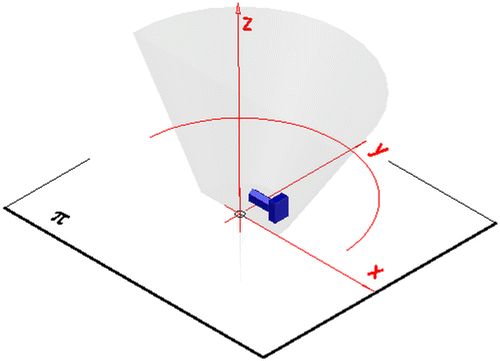
The projection apparatus of an inverse conical panoramic projection is defined similarly to the projection apparatus of the inverse cylindrical panoramic projection presented in [Citation21]. However, in the case of the inverse conical panoramic representation, the projection surface τ is a rotational conical surface or a fragment of this surface. Due to this fact, the projection apparatus of the inverse conical panoramic representation is composed of the rotational conical surface τ (or the part of it), a base plane π perpendicular to the surface’s axis l and a view point S X. A changeable view point moves on a circular or a straight path which are located outside the projection surface and are included in a horizontal plane χ parallel to the base plane π. The centre of the circle of viewpoints is located on the axis l, Figure .
Figure 1. Projection apparatus of a conical panorama. (a) Panorama from a point SX moving on a straight line. (b) Panorama from a point SX moving on a circular path.

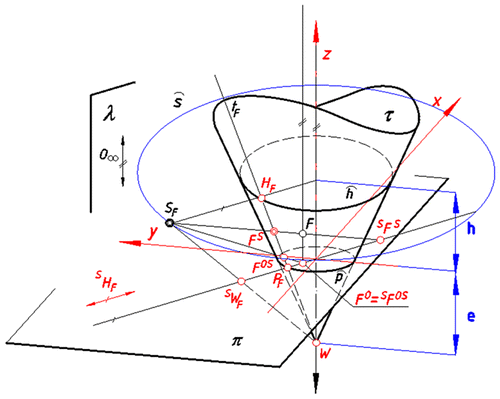
Depending on the location of the surface’s vertex W towards the base plane π we can distinguished two variants of the projection apparatus: above – variant A, below-variant B, Figure . A changeable centre S F of perspective projection is establish for the given real point F by cutting the circle s/the line s by a half-plane λ determined by the edge l and the point F, Figure .
Figure 2. Representation of a point F in conical panorama. (a) A view point S F located on a circular path. (b) A view point S F located on a straight path.
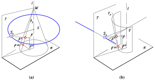
The image of any point F in inverse perspective onto a conical projection surface is received in the same way as the image of any perspective representation, that is as a piercing point of a projection ray with the projection surface τ. The projection ray joins the changeable centre of projection S F with the given point F. For the restitution purpose, similarly as in the case of vertical perspective onto a flat projection plane, we additionally project the point F O. The point F O is the orthogonal projection of a given point F received on the base plane π. Due to this fact, the image of any point F in inverse conical panorama is a pair of two projections (F S, F OS); a main one and an auxiliary one. The main projection F S is the central projection onto a rotational conical surface τ (or a part of it) from the moving centre S F. The auxiliary projection F OS is a main projection of F O onto τ, where F O is an orthogonal projection of F onto π, Figure . Both projections are contained in a ruling t F of the surface τ. This ruling is a main projection of a vertical line t going through a point F.
3. Materials and methods
For the graphical mapping of a panoramic image of a point F on a flat unrolled surface τ R, it is necessary to transform the panoramic image (F S, F OS) of this point contained in the surface τ to its counterpart included in an unrolled surface τ R. It can be realised by the projection of a ruling t F containing (F S, F OS) from a centre S F onto a base plane π, and next establishing projective relations between the points of the ruling S t F (received during projection) and their counterparts included in an unrolled surfaceτ. Similar approach was presented in the case of an inverse panorama projection onto a cylindrical projection surface as well as in the case of a classical panorama onto a conical surface and a panorama on a polyhedral projection surface [Citation21,22,24].
3.1. Establishing equations displaying geometrical relation occurring during projection from the centres dispersed on a circle
3.1.1. Inverse conical perspective of version A
Let us consider a ruling t F , which is attributed to the given point F during projection onto τ and which contains projections (F S, F OS) of F. We distinguish four characteristic points included in the ruling t F ; P F , H F , W F , F O,S, where a point P F is included in a base circle p, a point H F is included in a horizon circle h and a point W F = W is a vertex of the surfaceτ, Figure .
Figure 3. Central projection S t F of a generatrix line t F from S F onto π in order to realise the transformation.
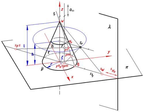
After the projection of the ruling t
F
from a centre S
F onto a base plane π we respectively receive points: S
P
F
, S
H
F
, S
W, S
F
O,S included in S
t
F.
During this projection, a cross ratio of the quadruple of these points is preserved, what can be shown by the equation below:(1)
(1)
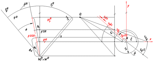
Also the range of points: S P F , S H F , S W F , S F O,S on the ruling S t F and the proper range of points: P F R , H F R , W F R , F O,SR on a ruling t F R included in the unrolled surface τ R are related by the projective transformation, see Figure .
Figure 4. Graphical connection between the range of points on the line S t F and a proper range of points on the line t F R included in the unrolled conical surface τ R.
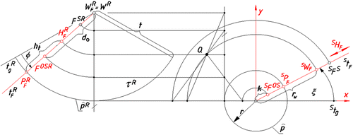
Due to this fact the cross ratio of the quadruple of these points is preserved during transformation, which can be expressed by the equation below:(2)
(2)
Determining, Figure :
| • | the radius of base circle by r | ||||
| • | the distance of the point S W F from the centre of the base circle p by r w | ||||
| • | the distance of the point S F O,S = F O from the centre of the base circle p by k, | ||||
| • | the distance of the point F O,SR from the point W F R by d o , | ||||
| • | the distance of the point H F R from the point P F R by h t , | ||||
| • | the distance of the point P F R from the point W F R by t | ||||
| • | and according to Figure Equation (Equation2 | ||||
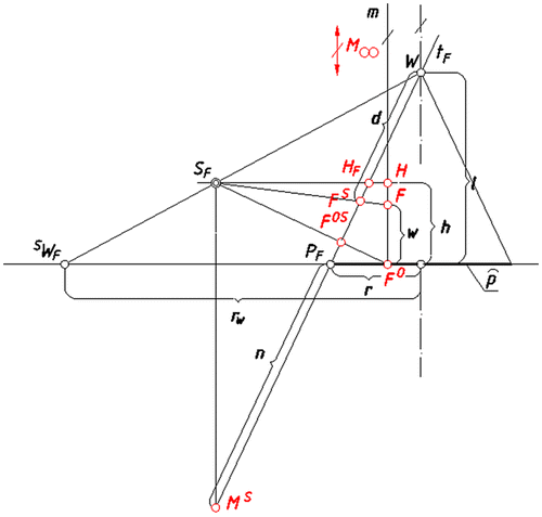
Figure 5. Graphical relation between points:M ∞, H, F, F O included in a vertical line m and their projections: M ∞, H F , F S , F OS ontoτ.
(3)
(3)
Let us further consider a vertical straight line m going through point F with a series of characteristic points M ∞, H, F, F O included in it, Figure .
According to Figure we can state that this range of points: M
∞, H, F, F
O
contained in m is homologous with an appropriate range of points M
∞, H
F
, F
S
, F
OS
included in the ruling t
F
and received after projection of m onto τ. This relation can be expressed in a following way:(4)
(4)
Determining, Figure :
| • | the height of horizon by h | ||||
| • | the distance of the point F O from the point F by w | ||||
| • | the radius of the circle of viewpoints by r S | ||||
| • | the distance of the point F S from the point W by d, | ||||
| • | the distance of the point P F from the point W by t, | ||||
| • | the distance of the point N F from the point P F by n, | ||||
| • | and according to Figure Equation (Equation4 | ||||
(5)
(5)
The parameters do and d describe the location of the main and auxiliary projections (F SR, F OSR) on the generatrix t F R in the unrolled surface τ R.
3.1.2. Inverse conical perspective of version B
Analogously to the case of conical perspective of version A, we project a ruling t F from a centre S F onto a base plane π and establish a geometrical relation between the proper points of this ruling during projection and their counterparts on an unrolled conical surface τ R, Figure .
Figure 6. Central projection S t F of a generatrix line t F from S F onto π in order to realise the transformation.
Due to the fact that cross ratio of the quadruple of the collinear points: P
F
, H
F
, W, F
O,S is invariant during projection, the Equation (Equation1(1)
(1) ) can be applied in this case too. Similarly to the case of version A of the projection apparatus, the points: S
P
F
, S
H
F
, S
W
F
, S
F
O,S on the ruling S
t
F
and the points: P
F
R
, H
F
R
, W
F
R
, F
O,SR
on the ruling t
F
R on the developed surface τ
R are related by the projective transformation, see Figure .
Figure 7. Graphical connection between the range of points on the line S t F and a proper range of points on the line t F R included in the unrolled conical surface τ R.
This relation is expressed by the equation below:(6)
(6)
Therefore, determining, Figure :
| • | the radius of base circle by r p | ||||
| • | the distance of the point S W F from the centre of the base circle p by r w | ||||
| • | the distance of the point S F O,S = F O from the centre of the base circle p by k, | ||||
| • | the distance of the point F O,SR from the point W F R by d 0 , | ||||
| • | the distance of the point H F R from the point P F R by h t , | ||||
| • | the distance of the point W F R from the point P F R by e t , | ||||
the Equation (Equation6(6)
(6) ) looks as follows:
(7)
(7)
In turn, perspective relations between the series of points on the vertical line m and appropriate points on the ruling t
F
received by projection of m onto τ (similarly as in the case of the projection apparatus of version A- Section 3.1.1) permit derivation of the following equation, Figure :(8)
(8)
Figure 8. Graphical relation between points: M ∞, H, F, F O included in the vertical line m and their projections: M ∞, H F , F S , F OS ontoτ.
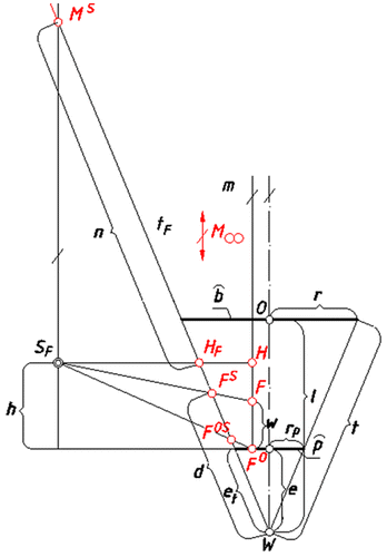
In the above equation n it is the distance of the point M S from the point H F,Figure .
3.2. Establishing equations displaying geometrical relation occurring during projection from the centres dispersed on a straight line
The inverse projection from a view point S F moving on a straight path s can be treated as the inverse projection from a centre S F moving on a circular path with a changeable radius r s. The way of the determination of the value of the changeable radius r S is the same as in the case of an inverse cylindrical panorama presented in [Citation21].
In order to determine it, we place a Cartesian coordinate system of axes x, y, z in such a way that x and y are included in a base plane π and x is parallel to a line s
0, which is an orthogonal projection of the line s onto π, Figure . According to it, we can state that r
s is a function of an angle ξ, which can be expressed as follows:(9)
(9)
Figure 9. The scheme displaying a relationship between the distance rs (between SF and the origin of the system of axis x, y) and the angle ξ..
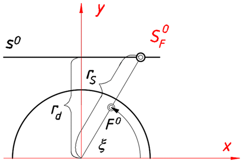
In the above equation r d is the distance of a line s 0 (orthogonal projection of s onto π) from the origin of the coordinate system x, y, z, Figure .
It is worth noting that in the case of the conical projection from the centre moving on a straight path according to representation definition only a half panorama can be achieved.
4. Results
4.1. Developing algorithms for drawing inverse conical perspective of a line
The hereby considered panoramic representation onto a conical projection surface is a nonlinear projection. Due to this fact, it cannot be expressed by any linear transformation [Citation25–27], however, Equations (Equation3(3)
(3) ), (Equation5
(5)
(5) ), (Equation7
(7)
(7) ) and (Equation8
(8)
(8) ) define the position of the image (F
SR, F
OSR) of any point F on the unrolled surface τ
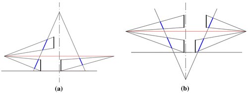
R. In turn, it enables developing algorithms for drawing an inverse panoramic projection of any straight line with computer aid like in [Citation21,22,24]. Basically, the perspective projection onto a conical surface of any straight line depends on its location towards the projection apparatus. According to our previous considerations we can state that the image of a vertical segment of a straight line is a segment of a line included in the surface’s ruling. The length of this segment is determined by distances d and do defined by Equations Equation3
(3)
(3) , Equation5
(5)
(5) , Equation7
(7)
(7) and Equation8
(8)
(8) and it is always equal d-do. However, this value depends on the height of the segment itself, its location towards axis l, as well as the definition of the projection apparatus, Figure . The closer the vertical segment is located to the axis l the shorter the length of its image.
Figure 10. Images of segments of vertical straight lines. (a) Projection of version A. (b) Projection of version B.
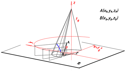
Panoramic images of lines being not vertical are always curved lines. In order to develop algorithms for drawing images of such lines, we place Cartesian coordinate system of axis x, y, z in such a way that x and y are included in the base plane π and z overlaps with the axis l, Figure .
Next, using the equations derived in Section 3.1.1, 3.1.2, 3.2 we can develop analytical algorithms for drawing a panoramic image of a line AB passing through two different points A(x a, y a, z a) and B(x b, y b, z b) defined by their spatial coordinates in the system x, y, z. For that reason let us consider the straight line AB determined by points A(x a, y a, z a) and B(x b, y b, z b).
For any straight line AB included in the plane being not perpendicular to the axis x is as follows:(10)
(10)
where k is the distance of the point F
O
from the centre of the base circle p as it was established previously in point 2.1.1 and 2.1.2. When the straight line AB is perpendicular to the axis x and is not vertical, the formulas look as follows:(11)
(11)
Equations (Equation10(10)
(10) ) and (Equation11
(11)
(11) ) enable to establish changeable parameters k and w, which are next applied in (5) and (8).
For the straight line AB included in the plane being not perpendicular to the axis x is as follows:(12)
(12)
where:
(13)
(13)
For the straight line AB perpendicular to axis x:(14)
(14)
where:(15)
(15)
and ξ is the angle between S t g and S t F measured on π (see Figures ).
The panoramic image of the line is created directly on the unrolled conical surface τ R. It is drawn as a plot of function d(Φ) in the polar coordinate system of axis. The variable Φ occurring in the function d(Φ) is dependent on ξ.
The relationship between ξ and Φ is as follows:(16)
(16)
(17)
(17)
For a given point F ∈ AB, an angular coordinate Φ is the angle between the border generatrix t g R and the generatrix t F R containing a panoramic image F SR on the unrolled projection surface, Figures and . The vertex W R contained in the unrolled surface is chosen as a pole, whereas the border ruling t g R is taken as a polar axis. In both cases A and B of panoramic projection onto a conical surface, it is convenient to establish as a border ruling the ruling t g, which projection S t g onto π is included in the axis x (see Figures , and ).
The capability of drawing lines in an inverse conical perspective projection enables drawing wire frame models of spatial objects. They are created as a set of images of line segments being the edges of the represented objects.
4.1. Drawing inverse conical panorama with computer aid- some examples of the algorithms’ applications
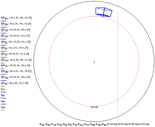
The starting point for inverse conical panorama construction with computer aid is establishing base assumptions of the representation, that is the base elements of the representation apparatus, as well as the represented object location. The base elements of the projection apparatus are: a radius of a base circle r, the horizon height h, a radius of the circle of viewpoints r s, as well as the location of the surface’s vertex W towards the base plane π (distance l in the case of projection of version A and B, as well as distance e in the case of projection of version B), see Figures . As far as the object location is concerned, it should be located within the projection surface in the case of the full panorama or behind the projection surface in the case of the part panorama construction. Moreover, the represented object should be located in a cone of good vision in order to receive natural, not much deformed view. Let us show some examples of the application of the algorithms for drawing inverse conical panoramic images of the simple architectural object. As the first example it is shown inverse conical perspective of version A. The bottom of the building is a rectangle ABCD located in the base plane x y. The dimensions of the rectangle are as follows: AB = 22.63 m, BC = 19.8 m. The height of the walls equal 23 m and the height of the hip roof equals 5 m. The object location is given by its vertices’ coordinates in the system of axes: x, y, z, with the unit applied on each axis of 1 m, Figure . The coordinates of the object’s vertices are as follows: A(−40,−12,0), B(−56,4,0), C(−42,18,0), D(−26,2,0), E(−40,−12,−23), F(−56,4,23), G(−42,18,23), H(−41,3,28).
Figure 12. The occasion of the object towards the projection apparatus. (a) Axonometric view. (b) Orthographic view.
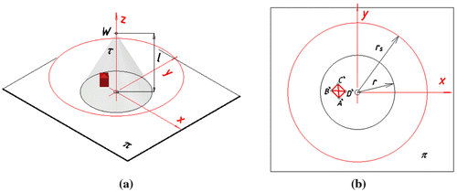
Mapping of the inverse conical panorama is realised directly on an unrolled projection surface as a set of plots of functions, which are the panoramic projections of the particular object’s edges. The plot of function for any edge depends on the coordinates of vertices belonging to this edge, Figure . The considered object is represented with the horizon height of 40 m. The horizon line is displayed in the image as a red dashed line. The radius r of the base circle equals 80 m, the radius r s of the circle of viewpoints equals 150 m and the distance l of the surface’s vertex W from the base plane π is equal 160 m.
In the Figure all visible lines during projection are marked in blue whereas not visible edges are marked with black dashed lines. Due to the object’s location the images of its two vertical edges overlap.
The next figures present panoramic images of the same building, however with horizon height of 100 m and with various radii of the circles of viewpoints, Figures . In the Figure we can see projections with the radius of the viewpoints circle of 150 and 120 m, whereas in the Figure panoramic projections with the radius of 90 and 70 m are presented.
Figure 14. Mapping of the multicentre inverse panorama with the horizon height of 100 m. (a) The radius of the circle of viewpoints equals 150 m. (b) The radius of the circle of viewpoints equals 120 m.

Figure 15. Mapping of the multicentre inverse panorama with the horizon height of 90 m. (a) The radius of the circle of viewpoints equals 90 m. (b) The radius of the circle of viewpoints equals 70 m.

As it is shown in the Figures and , if the radius of the circle of viewpoints equals 70 m, the curvature of the received lines’ images is bigger than in the case when the radius equals 150, 120 or 90 m. Due to this fact the panoramic projections from the farther distances seem to be more realistic. On the other hand, due to the inclination of the surface’s rulings, the closer the observer to the surface the more details of the object’s roof are visible.
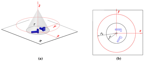
Figure 16. The location of the object towards the projection apparatus. (a) Axonometric view. (b) Orthographic view.
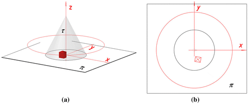
Another example shows a panoramic projection of the same building, however after its slight displacement. The location of the building is determined by coordinates of its vertices which are as follows: A(23.7,−48,0), B(1,−44.5,0), C(4.7,−25.1,0), D(26.9,−28.9,0), E(23.7,−48.3,24), F(1,−44.5,24), G(4.7,−25.1,24), H(26.9,−28.9,24), I(14.1,−36.7,30), Figure .
In this case of projection no lines which are projections of object’s edges overlap, Figure .
Figure 17. Multicentre inverse panorama with the horizon height of 20 m and with the radius r s of 150 m.
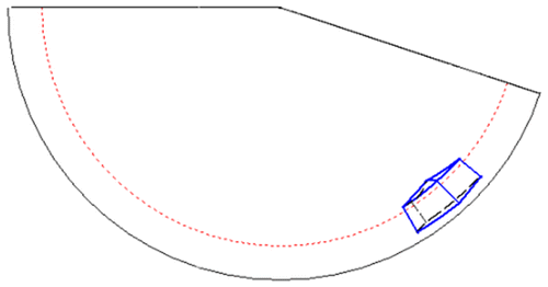
It is worth noting that, due to the way of the vertical edges convergence as well as the viewing direction perpendicular to the projection surface, it is recommended to apply a projection surface of version A for bird’s eye view and a projection surface of version B for frog’s eye view. Moreover, the represented object should be located in a cone of good vision during its rotation around the surface’s axis l, in order to receive a natural and not much deformed view, Figure .
Figure 18. The location of the circle of viewpoints in order to achieve natural view. (a) Bird’s eye view. (b) Frog’s eye view.

Another picture shows an inverse conical panoramic image of the object with the same vertices’ coordinates as in the Figure , however in the case of the projection apparatus of version B, Figure . Characteristics of the projection apparatus is as follows: the radius r s of a circle of viewpoints equals 150 m, the radius r of the base circle is 140 m, the distance e of W from π equals 70 m and the horizon height h equals 10 or 40 m, Figures and .
Figure 19. The location of the object towards the projection apparatus. (a) Axonometric view. (b) Orthographic view.
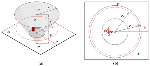
Figure 20. Mapping inverse panorama of version B (a) The horizon height of 10 m. (b) The horizon height of 40 m.
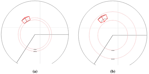
According to the results presented in Figure , as well as due to the slope of the surface’s rulings, and the fact that the object’s height is equal 28 m, it is recommended to apply horizon height less than 28 m to achieve realistic frog’s eye view of the represented building.
Comparing our method of perspective representation with inverse perspective of Byzantine times where straight lines diverge against the horizon, here the curves which are panoramic images of straight lines converge at the horizon. However, like in the case of Byzantine perspective onto flat projection plane, dependently on the object’s location towards the projection surface, its panoramic image can show more than its two sides. Such a case of the conical panorama from the centres dispersed on a circle is presented in the Figure . The characteristics of the projection apparatus is the same as in the previous examples, whereas the coordinates of the object’s vertices are as follows: A(−10,24,0), B(−10,34,0), C(30,34,0), D(30,24,0), E(−10,24,10), F(−10,34,0), G(30,34,10), H(30,24,10), I(−10,29,14), J(30,29,14), K(30,14,0), L(40,14,0), M(40,34,0), N(30,14,26), O(40,34,26), P(30,34,26), R(30,34,26).
Figure 21. Mapping of a conical panorama of version A with a specific object location so as three of its sides are visible in the projection. (a) The object’s location towards the projection apparatus. (b) Mapping of the panorama as a Mathcad plot.
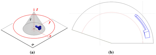
Byzantine perspective displaying the object from three sides onto a flat projection surface can seem to be not realistic. In our representation a panoramic image is a realistic view. That is due to the fact, that it should be observed not on a flat but curved surface during the observer’s movement, as well as due to the fact that the observer’s direction of vision is perpendicular to the projection surface. In such a way only two sides of the building can be visible in the same time during viewer’s movement on a circular path. It is worth noting that in the view presented in Figure (b) only visible lines have been expressed by solid lines. Invisible lines usually expressed by dashed lines are omitted.
In our method of projection we took into consideration only the points whose distances from the projection surface are less than the radius of the base circle. Due to this fact and according to the projection’s definition presented in point 1, the panoramic image of the buildings’ layout presented in Figure looks as it is shown in Figure . Considered layout of buildings was achieved by the location of another similar building in such a way that the coordinates of the vertices of its bottom included in π are as follows : A 1(11.9,−70.5,0), B 1(3.1,−65.6,0), C 1(22.5,−30.9,0), D 1(31.3,−35.8,0), K 1(40,−40.7,0), L 1(44.9,−32,0), M 1(27.4,−22.2,0).
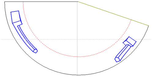
In order to represent a single building it is recommended to apply a half panorama. As the example of a half panorama projection we present the half panoramas of the same building, however with the projection apparatus of version B, Figure . The base elements of the projection apparatus are as follows: r = 160 m, r s = 150 m, l = 160 m, h = 20 m, e = 70 m.
The half panorama image depends on the object’s location. Below two half panoramas are presented with different object’s location, Figures and . The vertices’ coordinates of the building presented in the Figure are as follows: A(−10,24,0), B(−10,34,0), C(30,34,0), D(30,24,0), E(−10,24,10), F(−10,34,0), G(30,34,10), H(30,24,10), I(−10,29,14), J(30,29,14), K(30,14,0), L(40,14,0), M(40,34,0), N(30,14,26), O(40,34,26), P(30,34,26), R(30,34,26).
Figure 25. The half panorama of version B (a) The object’s location towards the projection apparatus. (b) Mapping of the panorama as a Mathcad plot.
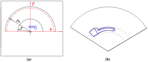
Figure 26. The half panorama of version B (a) The object’s location towards the projection apparatus. (b) Mapping of the panorama as a Mathcad plot.
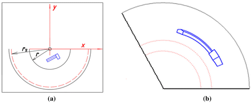
However, vertices’ coordinates of the building presented in the Figure are as follows: A(−8.6,−50.9,0), B(−13.5,−42.1,0), C(21.4,−23,0), D(26,−31.8,0), E(−8.6,−50.9,10), F(−13.5,−42.1,10), G(21.4,−23,10), H(26,−31.8,10), I(−11,−46.5,14), J(23.9,−27.4,14), K(31,−40.7,0), L(39.8,−35.9,0), M(30.1,−18.3,0), N(31,−40.7, 26), O(30.1,−18.3, 26), P(39.8,−35.9,26), R(21.4,−23,26).
In general, the image of any object in inverse conical panoramic projection depends on the structure of a projection apparatus, as well as the object’s location towards it. As far as the structure of the apparatus is concerned, it can be composed of a projection surface, being a full surface or a part of a surface. Additionally, the moving centres of projection, can be dispersed on a circular or on a straight line path. In the case of the full panoramic projection of the object which has common points with the axis l of the projection surface so-called object panorama can be achieved.
If we consider the conical inverse representation from the centres dispersed on a straight line s, only a part panorama can be achieved. Such a kind of the representation is shown in the Figures and . Both figures present the same building whose dimensions, as well as the location towards the system of axes is defined by its vertices’ coordinates: A(8,4,0), B(11.20,14.03,0), C(−6.67,20,0), D(−10,10,0), E(8,4,15), F(11.20,14.03,15), G(−6.67,20,15), H(−10,10,15), I(4.67,10.67,20), J(−3.33,13.33,20). In the first case we apply the type A of the projection apparatus with the following characteristics: r = 40 m, r d = 70 m, h = 30 m, l = 85 m, Figure .
Figure 27. Mapping of the inverse panoramic projection from a line s of version A: The object’s location; (b) Panoramic image of the object- Mathcad plot.
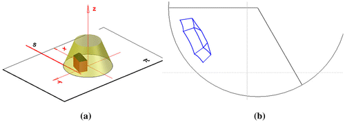
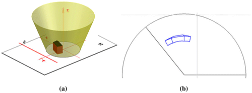
Figure 28. Mapping of the inverse panoramic projection from a line s of version B. The object’s location. (b) Panoramic image of the object- Mathcad plot.
According to the previous findings we have applied projection from high horizon to receive bird’s eye view, Figure (b).
However, in the Figure it is presented a panoramic projection onto projection surface of version B with following characteristics of the projection apparatus: r = 55 m, r d = 70 m, h = 15 m, l = 85 m, e = 77.5 m. In this case of projection frog’s eye view have been received, Figure (b).
5. Discussion
We presented a geometric approach to the construction of an inverse conical panorama projection from the centres dispersed on a circular or a straight path. The proposed method is a nonlinear projection in which each projection ray is contained in a plane perpendicular to the projection surface. In this way, the image of any object can be treated as a sequence of stitched pictures of zero width taken from a moving single view point. In the considered projection, the image of any architectural form depends on the structure of the representation apparatus, as well as on the object’s location. As far as the structure is concerned we distinguished two versions of the apparatus; A and B depending on the projection surface vertex’s location towards the base plane. Furthermore, we applied two variants of the view point location: a curved and a straight path.
In our method of projection we took into consideration only the points which distance from the projection surface is less than the radius of the base circle. It is possible to determine similar representation from dispersed centres for the points which are situated further from the surface than the length of the surface’s radius. In that case, however, a reverse image of the represented figures can be achieved. Therefore, it was omitted in our consideration.
The main aim of the proposed panorama creation was to draw a panoramic image directly on an unrolled projection surface with computer aid. Projective relation between points on each projection surface’s ruling and their counterparts on the unrolled surface enabled to develop algorithms for drawing panoramic images of straight lines. Curved lines, in order to be represented, should be approximated by some segments of straight lines. Owing to the application in our algorithms of the changeable base elements of perspective such as: the radius of the base circle r, the radius of the circle of viewpoints r S , the height of horizon h, we can achieve inverse conical panoramic images from a variety of viewing positions, as well as on a conical projection surface determined by different metric characteristics. Thanks to it our method appears universal and practical. Furthermore, the use of the moving viewpoint implies much more dynamic experience, which is closer to our actual experience of life than perspective from a vantage station point. Due to the fact that the panoramic projection has been described accurately by analytical equations, the accuracy of the method depends on the accuracy of the graphical package in which the equations are applied. In our case Mathcad Professional software calculates points’ coordinates with accuracy of three decimal places so we can say that the method is very accurate.
6. Conclusions
The elaborated algorithms for perspective drawing formulated and tested in Mathcad software work well, however, in order to make drawing more efficient and convenient as well as for the practical applications, they can be implemented in AutoCAD or any graphical package. It will be the aim of the author’s future work.
We presented geometrical approach to inverse conical panorama perception and its construction. We hope that this work will motivate further discussion on an inverse conical panorama from various angles. We also hope that our approach will mark a step towards the extension of potentially existing projection methods as well as it will motivate further discussion on new types of computer generated presentations of architectural forms.
Disclosure statement
No potential conflict of interest was reported by the author.
References
- Deregowski J , Parker D , et al . The perception of spatial structure with oblique viewing: an explanation for byzantine perspective? Perception. 1994;23:5–13. DOI:10.1068/p230005.
- Howard I . Drawing with divergent perspective, ancient and modern. Perception. 2010;40:1017–1033.
- Antonova C . On the problem of reverse perspective : definitions east and west. Leonardo. 2010;464–469. DOI:10.1162/LEON_a_00039.
- Amheim R . Inverted perspective in art: display and expression. Leonardo. 1972;5:125–135.
- Groncharov O. , Tiapovkin N . Interrelation between perspective constructions and constancy of magnitude perception. J Russ East Eur Psychology 2012:50. DOI 10.2753/RP01061-0405500502
- Marcikić I , Paunović M . Inverse perspective in Cézanne's art. FME Trans. 2017;45:301–306. DOI:10.5937/fmet1702301 M.
- Gibbons T . Cubism and ‘The fourth dimension’ in the context of the late nineteenth-century and early twentieth-century revival of occult idealism. J Warburg Courtauld Inst. 1981;44:130–147.10.2307/751055
- http://teverinafineart.com/artists/scott-grodesky.html. 2017 Aug 10.
- Available at http://www.patrickhughes.co.uk. 2017 Aug 10.
- Snyder JP . Flattering the earth: two thousand years of map projections. 1st ed. USA University of Chicago Press; 1993. p. 20–150. ISBN 9780226767475.
- Kennedy M , Kopp S . Understanding map projections. 1st ed. USA; 2001. p. 20–98. ISBN 13 978-1589480032.
- Lakhmi J , Favorskaya NM , Novikov D . Panorama construction from multi-view cameras in outdoor scenes. Comput Vis Control Syst. 2015;2:71–108.
- Meneghetti G , Danelljan M , Felsberg M , et al . Image alignment for panorama stitching in sparsely structured environments, image alignment for Panorama stitching in sparsely structured environments Panorama 19th Scandinavian Conference, SCIA2015; 2015 June 15–17; Copenhagen, Denmark. Lecture Notes in Computer Science. 2015. p. 428–439.
- Jeong J . Kim A . Adaptive inverse perspective mapping for lane map generation with SLAM. International Conference on Ubiquitous and Ambient Intelligence; 2016 Aug 19–22. IEE; China. p. 38–41.
- Nieto M , Salgado L , Jaureguizar F . Stabilization of inverse perspective mapping images based on robust vanishing point estimation. 200 vehicles symposium. Vols 1–3; 2007 July 13–15. IEE; Turkey. p. 862–867.
- Bertozzi M , Broggi A , Fascioli A . Stereo inverse perspective mapping: theory and applications. Image Vis Comput. 1998;16:585–590. DOI:10.1016/S0262-8856997000093-0.
- Lakhmi C , Favorskaya MN , Novikov D . Panorama construction from Multi-view cameras in outdoor scenes. Comput Vision Control Syst. 2015;2:71–108. DOI:10.1007/978-3-319-11430-9_4.
- Zhang Q , Jung J , Won J , Cho J . Object panorama creation based on a general photographing environment. Proceedings of the 5th International Conference on Ubiquitous Information Management and Communication ICUIMC; 2011 Feb 21–23; Seoul, Republic of Korea.
- Jong-Gil H , Kyoung-Wook P , Kyeong-Jin BK Eung-Kon . Cultural heritage sites visualization system based on outdoor augmented reality. AASRI Procedia. 2013;4:64–71. DOI:10.1016/j.aasri.2013.10.011.
- Firoozfam P , Negahdaripour S , Barufaldi C , A conical panoramic stereo imaging system for 3-D scene reconstruction OCEANS 2003 proceedings 2003; San Diego; Vol 4; p. 2303–2308. DOI:10.1109/OCEANS.2003.178268.
- Dzwierzynska J . Direct construction of an inverse panorama from a moving view point. Procedia Eng. 2016;161:1445–1451. DOI:10.1016/j.proeng.2016.08.634.
- Dzwierzynska J . A conical perspective image of an architectural object close to human perception . IOP Conf Ser: Mater Sci Eng. 2017;245:1–16. DOI:10.1088/1757-899X/245/5/052099.
- Cortizoab E , Moreno Yerasc A , Leporead JR , Garavagliaae M . Application of the structured illumination method to study the topography of the sole of the foot during a walk. Opt Lasers Eng. 2003;40:117–132. DOI:10.1016/S0143-8166(02)00056-8.
- Dzwierzynska J . Computer-aided panoramic images enriched by shadow construction on a prism and pyramid polyhedral surface. Symmetry. 2017;9(10):214. DOI:10.3390/sym9100214.
- Pottman H , Asperl A , Hofer M , Kilian A . Architectural geometry. 1st ed. Exton, PA, USA: Bentley Institute Press; 2007. 35–194. ISBN 978-1-934493-04-5.
- Haglund L , Fleet, DJ . Stable estimation of image orientation. Proceedings of 1st International Conference on Image Processing; 1994 Nov 13–16; Austin, TX, USA. p. 68–72.
- Salomon D . Perspective projection. In Transformations and projections in computer graphics ; Springer-Verlag: London, UK, 2006; p. 71–144, ISBN 978-1-84628-620-9

