
 ?Mathematical formulae have been encoded as MathML and are displayed in this HTML version using MathJax in order to improve their display. Uncheck the box to turn MathJax off. This feature requires Javascript. Click on a formula to zoom.
ABSTRACT
Possibilities of the coherent scanning tomography with negative-index metamaterial lens are studied. Such lens (a slab of negative refractive index material) has the power to focus the source field into a sounded media with dielectric inhomogeneities. The proposed solution of the corresponding inverse scattering problem, i.e. the retrieval of 3D distributions of the complex permittivity in the inhomogeneous region, is based on the 3D integral equation for the scattered field that is reduced to the one-dimensional Fredholm integral equation of the 1-st kind relative to the depth profile of lateral spectrum of inhomogeneities. After the solution of this equation for each pair of spectral components, the inverse Fourier transform leads to the desired solution. For solid targets, it appeared possible to retrieve the shape of their surface with the computing holography algorithm. This approach can be very suitable for diagnostics of media with a plane or flexible surface, in particular, in the biomedical diagnostics. The feasibility of this tomography for low-contrast targets is demonstrated in numerical simulation.
Introduction
As it was shown in [Citation1], a slab with negative permeability (μ) and permittivity (ε) has a negative refractive index and, hence, has a property to focus all the field components of the source transversal spectrum (including evanescent part of the spectrum) – that leads to the perfect resolution of 2D images of objects in the focal plane [Citation2]. Various methods to realize such left-handed metamaterials have been proposed; typically, they include arrayed metallic wires or electric resonators together with magnetic resonators [Citation3]. It appeared easier to realize left-hand metamaterials in the microwave range, as it was demonstrated experimentally in [Citation4]. In [Citation5], a tuneable left-handed transmission has been demonstrated experimentally in a ferromagnetic/ferroelectric composite metamaterial consisting of an array of yttrium iron garnet rods combined with barium strontium titanate rods, where both measured phase velocity and the refractive index of the CMM are shown to be negative at the relevant frequency range. Various metamaterials in microwave range have been developed and tested (see e.g. in [Citation6–12]). Also, approaches to metamaterials (including tuneable and metasurfaces) working at terahertz and optical frequencies have been developed [Citation13–25]. Quite compresence review of possible applications of metamaterials can be found in [Citation26].
This progress in the development of left-handed metamaterials stimulated studies of their applications to the left-handed lens subsurface diagnostics including those considered in this paper. Unlike previous studies, where possibilities of the scattered signal imaging have been considered, the proposed diagnostics includes the full quantitative analysis – determination of 3D distributions of complex permittivity of distributed subsurface inhomogeneities or the shape of solid targets (computing holography).
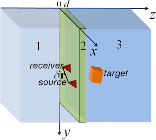
The focus of plane left-handed lenses can penetrate far into the studied region that opens a new possibility of the subwavelength scanning tomography. Propagating and evanescent wave components meet in the outer focus at zf = 2d − zs as if the source at z = zs were transferred to this point (see below in Figure , where transceiver system is scanning in the medium 1 through the lens 2). Varying the source z-position, this focus can be moved into the studied region 3 inside the interval d < zf < 2d. All components of the field scattered from any element of inhomogeneities are focused before the lens and form the target image with a subwavelength resolution [Citation2]. This possibility of a perfect lens imaging has been considered and simulated in [Citation27–31]. Moreover, as it was demonstrated in [Citation31], it is possible to develop a perfect lens tomography of 3D low-contrast inhomogeneities based on the solution of the inverse scattering problem by data of 2D lateral scanning at several levels behind the lens with the source–receiver system that changes the position of the focus throughout the studied region. The general scheme of multilevel scanning tomography, developed in [Citation31], has been applied to this inverse problem and studied in numerical simulation, where the subwavelength resolution has been realized.
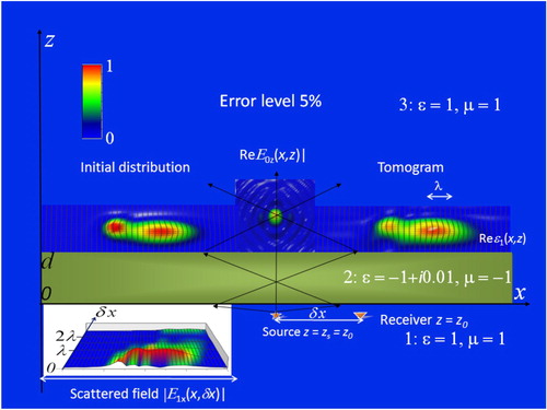
Figure 1. Scheme of bistatic left-handed lens tomography.
However, even a very small absorption in left-handed materials restricts drastically the range of subwavelength focusing [Citation32]. As a result, this range can’t noticeably exceed sizes of the near-field zone. To overcome this difficulty methods of losses compensation based on active media [Citation33–37] or the effect electromagnetically-induced transparency have been proposed [Citation38]. However, other factors, such as the limited size of perfect lenses and their mismatch with media, lead to similar restrictions of the achievable resolution.
Nevertheless, the possibility to use the property of plane left-handed lenses to focus the probing field into a studied region remains very attractive for applications in the subsurface tomography. Methods of such a tomography with non-perfect metamaterial lenses are proposed and studied here – including conditions of their mismatch with surrounding media. These methods are based on the solution of corresponding inverse scattering problems in frameworks of the general approach of scanning tomography proposed in [Citation39] – the solution of corresponding 3D integral equations in the schemes when they appear to be convolution equations over lateral co-ordinates – that enables to reduce they to one-dimensional equations. Here we study schemes of bistatic 2D scanning measurements based on multilevel and multi-base measurements with the fixed emitter-receiver distance (base). The multilevel scheme of 2D scanning at the condition of the fixed emitter-receiver distance has been invented in [Citation40]. This scheme has been successfully applied by us in the microwave near-field scanning subsurface tomography in [Citation40,Citation41]. The proposed here multi-base scheme uses data of multiple 2D scanning at the fixed distance z of transceiver system from the lens with variable values of parameters of the base vector
(see in Figure ). In both schemes, the 2D Fourier transform (plane wave decomposition) reduces 3D integral equations for the scattered field to the one-dimensional Fredholm integral equation of the 1-st kind relative to the depth profile of lateral spectrum of permittivity inhomogeneities. The solution begins with the Born approximation; corrections can be obtained in the iterative process [Citation31,Citation40].
This study develops a new approach in methods of noninvasive subsurface electromagnetic diagnostics that can be applied in a wide range of biomedical diagnostics, nondestructive testing and subsurface radar sounding. Besides the above-mention papers, it is worth mentioning other old available approaches to the subsurface diagnostics: methods of geomagnetic diagnostics of the Earth’s crust [Citation42–49], method of total-internal-reflection tomography [Citation50,Citation51], globally convergent approach [Citation52,Citation53], method of dual regularization in the diagnostics of one-dimensional subsurface inhomogeneities [Citation54], microwave pulse subsurface tomography and holography [Citation55], and method of subsurface acoustics tomography [Citation56]. Also, there are interesting studies related to diagnostics of the permittivity of dielectric obstacles and layered structures in waveguides [Citation57–59].
Inverse problem of scattering
Let us consider the inverse problem of scattering in proposed schemes of the metamaterial lens tomography (see in Figure ). The source and receiver are placed in the layer 1; the layer 2 is the metamaterial lens; the studied 3D inhomogeneous region ϵ1(r) is imbedded in the layer 3. In the presence of the scattering region, the electric field is determined as the sum of the probing and the scattered fields :
(1)
(1)
The probing field
is determined by the proper Green tensor
(that includes near-field components):
(2)
(2)
where
is the current distribution in the source. Using the plane wave decomposition of (2) over lateral co-ordinates, it is possible to obtain Green functions
in any layered medium [Citation31]. The solution of the inverse scattering problem is based on the corresponding 3D non-linear integral equation for the scattered field that can be solved iteratively, beginning with the Born approximation [Citation31, Citation40]:
(3)
(3)
It is a very complicated problem, but methods are proposed in [Citation31,Citation39,Citation40] to reduce this equation to a convolution equation over lateral co-ordinates. In this paper, the method [Citation31] is in use, where data of 2D scanning are collected in the bistatic scheme of measurements at the condition of the fixed the source–receiver spacing
. At this condition, the sounding field structure will be invariable relative to the receiver position that leads to the significant improvement of the accuracy of measurements because all observed variations are related only to studied inhomogeneities. This representation makes it possible to reduce the 3D integral equation to 1D integral equation relative to the depth profile of the lateral spectrum of
, using 2D Fourier transform over transverse co-ordinates [Citation31]:
(4)
(4)
where
,
are components the lateral 2D Fourier transform of Green functions
in (1)–(3) that determine the contribution of jth component of the source to ith component of the field at the receiver position in the kth layer and the position of the sounded region in the lth layer. Components of Green function
in Cartesian co-ordinates are expressed simply as 2D inverse Fourier transforms of
,
. These Green functions and transfer coefficients
for TM and TE polarizations are presented in [Citation6] for arbitrary multilayer media.
Then some corrections to results obtained in the Born approximation from (4) can be obtainted in frameworks of iterative algorithm proposed in [Citation31]:
(5)
(5)
where the second term in (5) is a correction to the scattered field.
In the compact notation of (4), (5), corresponding one-dimensional Fredholm integral equations of the 1-st kind can be written as
(6)
(6)
that should be solved relative to the vertical profile of permittivity for each pair of transversal spectral components. Then, inverse Fourier transform gives us the desired solution of the tomography problem:
(7)
(7)
To solve this equation, it is possible to use dependence of the kernel of (5) on the vertical position of the receiver z that determines the focus position in the sounded medium (multilayer method). This method has been proposed and studied in the numerical simulation in [Citation31] for the case of perfect left-handed lenses. Here we study this method for non-perfect lenses and absorbing non-matched media. In cases, when the multilayer scanning is unsuitable, it is proposed here a new multi-base method – to use the dependence of the kernel on components of the vector
, making the scanning with the fixed altitude and at several base parameters.
To retrieve complex-value profiles from the one-dimensional Fredholm integral equation of the 1-st kind (5), the mathematically consistent algorithm has been applied that is based on the Tikhonov’s principal of generalized discrepancy developed for complex-value functions in the
Hilbert space (Sobolev’s space) [Citation31]. The regularization parameter is determined by the integral error of lateral spectrum of the scattered field. This spectrum error can be derived from the known integral error of the measured signal using the Plansherel’s theorem. Finally, the desired 3D structure of permittivity is obtained by 2D inverse Fourier transform of the retrieved profiles of lateral spectrum components. It is also possible to take into account the transfer function of the receiver taking into account that the received signal is determined by the convolution of field and apparatus function components in the same way as in [Citation40,Citation41].
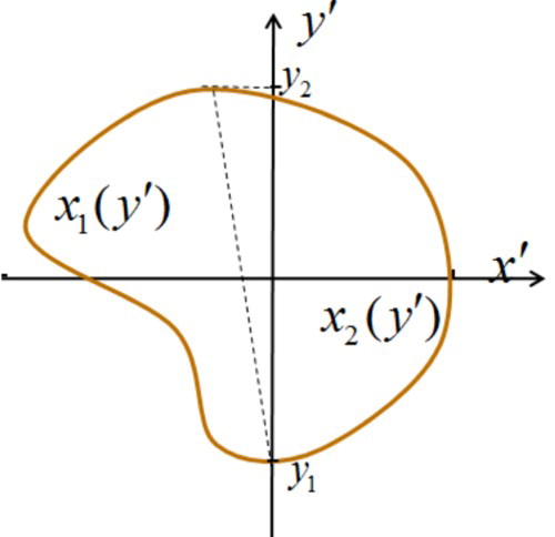
For rather typical cases of solid, internally homogeneous targets, it is enough to solve the problem of their shape retrieval, i.e. the problem of computing holography. This method has been proposed and applied in microwave multifrequency holography [Citation40,Citation41], where the solution of (5) in k-space has been in use assuming that we deal with a target with . Then, expressing the target shape of a singly connected target as two functions
(see in Figure ), obtain the complex-valued transcendent equation for the Fourier transform of
over one of spectral components ky,
(8)
(8)
The solution of (8) as the equivalent system of two real-valued equations for two unknown variables x1 и x2 gives us the desired target shape.
Figure 2. The boundary of a solid target section .
The equation (5) is overdetermined, so there is the possibility of optimization. Based on results of numerical simulations, it was found that better results are obtained at the choice , where L is the estimation of the typical size of a target that can be derived from the visualized image of the scattered signal.
Numerical simulation
Multilayer method
In this method, the integral Equation (6) can be written as
(9)
(9)
By scanning with the transceiver system at several levels z, we can change the depth of the field focus in a sounded medium, find inhomogeneities, and receive the scattered signal for tomography diagnostics.
The scheme of the numerical simulation includes: (a) calculation of 2D distribution of the scattered field for given inhomogeneities in the range of analysis; (b) adding of random normally distributed ‘measurement errors’ with the assumed level in the L2 metric; (c) solving of the inverse scattering problem; (d) comparison of initial and retrieved distributions of inhomogeneity parameters.
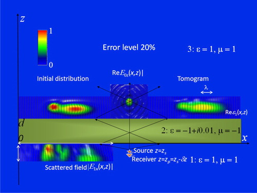
In Figures and , results of the numerical simulation of the proposed multilevel scanning tomography for the case of absorbing metamaterial lenses are shown for the real part of simulated inhomogeneous permittivity for the lens with permittivity at two different depth positions of inhomogeneities at the 5% level of simulated random errors. To retrieve the simulated distribution of 3D complex permittivity ϵ(r), the z-component of the scattered field
‘measured’ in x–y plane at the vertical distance δz = –0.1λ from z-component point source of the probing field j(r″–r–δr) = jzδ (r″–r–δz)z0 at six levels z = zi beyond the lens (in the range marked with arrows) has been used in analysis. The studied inhomogeneity above the metamaterial lens was simulated by the sum of two gauss asymmetry distributions that are the same for real and imaginary parts of permittivity. Their sizes are somewhat larger than wavelength λ (marked with arrow). Field amplitude distributions are given in relative (to their maximal values) units.
Figure 3. Metamaterial lens tomography (vertical section). Layer 1: (left) received scattered field in the range of scanning (marked with red arrows); (centre) source–receiver system. Layer 2: lens. Layer 3: (left) initial distribution of inhomogeneities; (centre) z-component of the probing field; (right) retrieved distribution of inhomogeneities (tomogram).
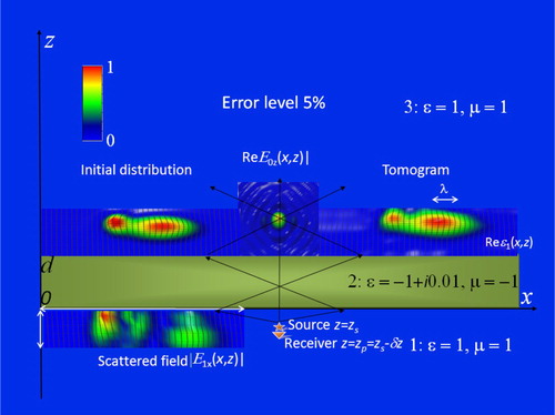
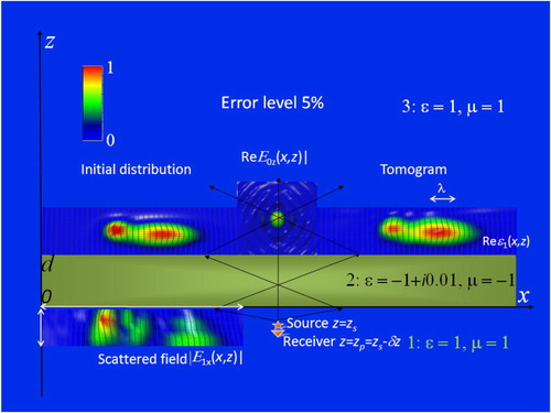
Figure 4. The same notation as in Figure .
Results demonstrate a high-quality retrieval of the initial distributions throughout the region of focusing. The quality and accuracy of positioning obtained for real and imaginary parts of the permittivity of retrieved inhomogeneities are about the same.
In Figure results are given for the same case as in Figure , but retrieved at 20% error’s level. One can see that the retrieved image is rather smoothed; however, its common shape and position are reproduced quite correct.
Figure 5. The same inhomogeneity and notation as in Figure , but at 20% error level.
More considerable mismatches between media and lens lead to reflection on interfaces and multiple focusing, as it is possible to see in Figures and , where tomography results for real and imaginary parts of complex permittivity are given for the case, where media are mismatched with each other and with the lens. In this case, for sounding in the medium with , it appears possible to retrieve smaller inhomogeneities than those in Figures –.
Figure 6. the same notation as in Figures –.
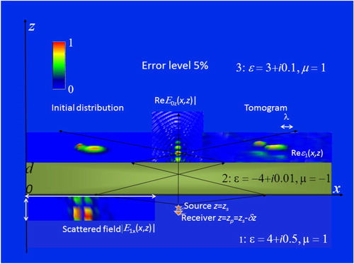
Figure 7. The same notation as in Figure , but tomography results are given for imaginary part of permittivity.
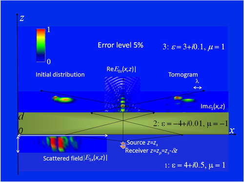
Because of reflection on boundaries of mismatched media, one can see the multiple focusing in Figures and ; however, the main details of the inhomogeneous structure are reproduced in retrieved distributions rather correct. In Figure , it is possible to see artefacts related to the secondary scattering below the retrieved image of the real part of permittivity. These artefacts are absent in images of the imaginary part of permittivity shown in Figure .
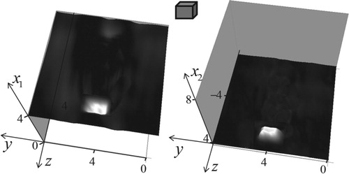
Results of tomography and holography analysis for the solid parallelepiped target with sizes 2.5 × 3.2 × 1.5 (given in wavelengths in the medium) are demonstrated in Figures –. The solution of the tomography problem in k-space based on solving (9) for this target is shown in Figure for the parameters of media and lens shown in Figures and . In Figures and , results of tomography analysis in Cartesian co-ordinates are demonstrated for this target.
Figure 8. Solution of inverse scattering problem in k-space for the parallelepiped target shown in Figure at the depth of its centre section. Left, calculated distribution; right, result of retrieval at the data error 5%.
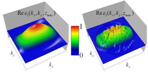
Figure 9. The same notation as in Figure .
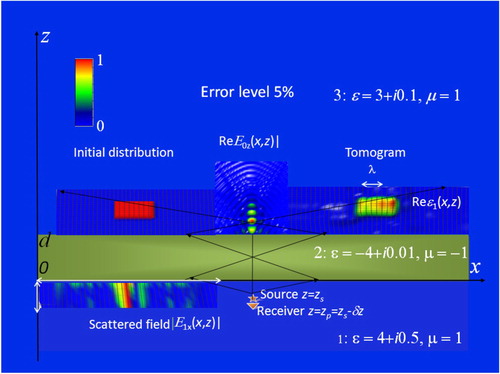
Figure 10. The same notation as in Figure .
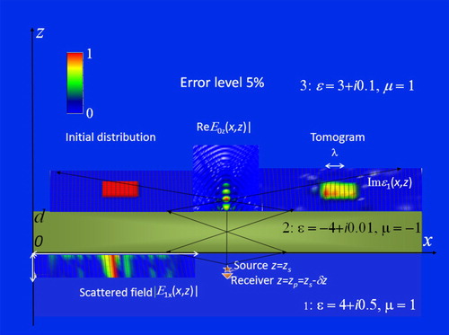
Figure 11. Visualization of holography analysis as two functions (see in Figure ) based on the solution of (8) for the rectangular target (insertion). Sizes are given in wavelengths.
One can see that the shape and positions of permittivity distributions are retrieved quite correct; however, sharp edges are quite smoothed.
If it is known a priori, that we deal with solid targets, it is possible to apply in analysis the holography algorithm based on the solution of (8) with the use of the k-space solution of (9) shown in Figure . In Figure , the results of this holography analysis are demonstrated.
As it is seen in Figure , holography images of two halves of the target surface are retrieved quite correct, and they are free from artefacts. It is possible to note here, that, unlike well-known optical holography, where some part of targets remains invisible, this method gives the shape of the whole target surface.
Multi-base method
The multi-base method can be more suitable in applications than the multilevel method, for example, in biomedical diagnostics. In such cases, the integral Equation (6) can be written as
(10)
(10)
Measurements should be carried out at the fixed distance from the lens surface (or in contact with) in dependence on parameters
of the base vector
. At every choice of the variable parameter, the information is related to the depth sensitivity to variations of the kernel of (10) at changes of chosen base parameter. So, there are various possibilities to realize this method by the choice of the variable parameter. If one chooses to use
as the variable parameter, there are also various possibilities to collect data of scanning: scanning at the multilevel position of the source (at various
), or that at various positions of the receiver
. In both cases, there is a freedom to choose z-level of the receiver or source respectively. If one chooses to fix z-position of the source, the integral equation (10) can be written as
(11)
(11)
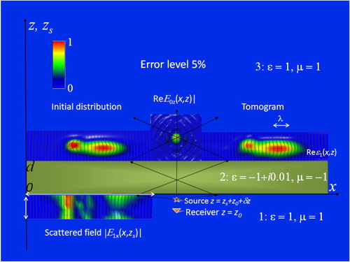
This kind of the multi-base method can be, in fact, considered as a version of the multilevel method because one has the multilevel scanning with respect to the variable z-position of the source. And really, in the numerical simulation results appeared to be very similar. In the numerical simulation of this multi-base method of scanning tomography shown in Figure , results are obtained for the same lens and same inhomogeneities as in the case shown in Figure . To retrieve the simulated distribution of 3D complex permittivity ϵ(r), the 2D distribution of the scattered field component beyond the lens has been calculated at the fixed vertical receiver position z0 = −1.0λ at 6 z-positions of the source zs = zi of the probing field j(r″–r–δr) = jzδ (r″–r–δzi)z0 (in the range marked with white arrows in Figures and ).
Figure 12. Metamaterial lens tomography (vertical section). Layer 1: (left) received scattered field in the range of scanning (marked with white arrows); (center) source–receiver system with fixed z-position of the receiver and variable z-position of the source. Layer 2: lens. Layer 3: (left) initial distribution of inhomogeneities; (center) z-component of the probing field; (right) retrieved distribution of inhomogeneities (tomogram).
In some cases, it can be not suitable to scan the scattered field at several distanced from the lens. At that, one can choose (or
) as the variable parameter and collect data at the fixed z-position of the source and receiver. The integral equation (10) can be written in this case as
(12)
(12)
Results of the numerical simulation of this kind of the multi-base method shown in Figure are obtained for the same lens and same inhomogeneities as in the case shown in Figures and . To retrieve the simulated distribution of 3D complex permittivity ε(r), the 2D transversal distribution of the scattered field component
beyond the lens has been calculated at the same source and receiver z-positions z0 = zs = –1.0λ at six values of the source–receiver offset
in the region 0–2.5λ so that j(r″–r–δr) = jzδ (r″–r–δxi)z0.
Figure 13. Metamaterial lens tomography (vertical section). Layer 1: (left) received scattered field in the range of scanning (marked with red arrows) at various base parameters ; (centre) source–receiver system with the same z-positions of the receiver and the source. Layer 2: lens. Layer 3: (left) initial distribution of inhomogeneities; (centre) z-component of the probing field; (right) retrieved distribution of inhomogeneities (tomogram).
It is possible to note that in the distribution of the scattered field appeared the most sensitive to inhomogeneities at the base parameter in the chosen scheme (see in insertion in layer 1). As it is seen in Figure , simulated inhomogeneities are retrieved quite correct; however, retrieved images are somewhat smoothed when compared to results shown in Figures and . In this connection, it is worth mentioning that this simulation demonstrates only some of of possible realizations of this method.
Conclusion
The studies of applications of left-handed lens for the subsurface diagnostics considered in this paper were stimulated by the recent progress in the development of left-handed metamaterials. Unlike previous works, where imaging methods based on the scattered signal visualization has been proposed, the considered here diagnostics gives full quantitative information about 3D distribution of distributed subsurface inhomogeneities of complex permittivity (holography method) or the shape of solid targets (tomography method) from the solution of corresponding inverse scattering problems by data of bistatic measurements of complex amplitudes of the scattered signal in 2D region above the media with subsurface inhomogeneities. Multilevel and multi-base schemes of input data formation have been studied in developed algorithms. At that, measurements should be carried out at fixed base parameters of transceiver system during each scanning that enables to reduce the initial 3D inverse problem to the multiple solution of the one-dimensional integral equation and, hence, realize much better resolution. The feasibility of the proposed methods of scanning tomography and holography has been demonstrated in the numerical simulation. These methods can be especially useful in diagnostics of media with planar or elastic boundaries, for example, in the biomedical diagnostics or defectoscopy.
The progress in the construction of tuneable metamaterial lenses opens the possibility to develop also the multifrequency left-handed tomography. The corresponding multifrequency inverse scattering problem has been successfully applied in the multifrequency microwave tomography of underground dielectric targets in [Citation39-41]. Developed methods can be also realized with metasurfaces planar left-handed lenses (see e.g. in [Citation60–63]) that are simpler in production and can be more suitable in use than bulky lenses.
Disclosure statement
No potential conflict of interest was reported by the author.
Additional information
Funding
References
- Veselago VG. The electrodynamics of substances with simultaneously negative values of and μ. Sov Phys Uspekhi. 1968;10:509–514. (in Russian). doi: 10.1070/PU1968v010n04ABEH003699
- Pendry JB. Negative refraction makes a perfect lens. Phys Rev Lett. 2000;85:3966–3969. doi: 10.1103/PhysRevLett.85.3966
- Smith DR, Padilla WJ, Vier DC, et al. Composite medium with simultaneously negative permeability and permittivity. Phys Rev Lett. 2000;84(18):4184–4187. doi: 10.1103/PhysRevLett.84.4184
- Shelby RA, Smith DR, Schultz S. Experimental verification of a negative index of refraction. Science. 2001;292:77–79. doi: 10.1126/science.1058847
- Ziolkowski RW. Design, fabrication, and testing of double negative metamaterials. IEEE Trans Antennas Propag. 2003;51:1516–1529. doi: 10.1109/TAP.2003.813622
- Zhao H, Kang L, Zhou J, et al. Experimental demonstration of tunable negative phase velocity and negative refraction in a ferromagnetic/ferroelectric composite metamaterial. Appl Phys Lett. 2007;93:201106-1–201106-3.
- Turkmen O, Ekmekci E, Turhan-Sayan G. Nested U-ring resonators: a novel multi-band metamaterial design in microwave region. IET Microwaves Antennas Propag. 2012;6(10):1102–1108. doi: 10.1049/iet-map.2012.0037
- Islam SS, Faruque MRI, Islam MT. The design and analysis of a novel split-h-shaped metamaterial for multi-band microwave applications. Materials (Basel). 2014;7:4994–5011. doi: 10.3390/ma7074994
- Liu Y, Zhou X, Song K, et al. Quasi-phase-matching of the dual-band nonlinear left-handed metamaterial. Appl Phys Lett. 2014;105(20):201911-1–101911-4.
- Hasan MM, Faruque MRI, Islam SS, et al. A new compact double-negative miniaturized metamaterial for wideband operation. Materials (Basel). 2016;9:830. doi: 10.3390/ma9100830
- Zhou H, Wang C, Peng H. A novel double-incidence and multi-band left-handed metamaterials composed of double Z-shaped structure. J Mater Sci: Mater Electron. 2016;27(3):2534–2544.
- Li S, Elsherbeni AZ, Yu W, et al. A novel tunable dual-band left-handed metamaterial. J Magn. 2017;22(4):610–616. doi: 10.4283/JMAG.2017.22.4.610
- Khoo C, Werner DH, Liang X, et al. Nanosphere dispersed liquid crystals for tunable negative–zero–positive index of refraction in the optical and terahertz regimes. Opt Lett 2006;31:2592–2594. doi: 10.1364/OL.31.002592
- Shadrivov IV, Morrison SK, Kivshar YS. Tunable split-ring resonators for nonlinear negative-index metamaterials. Opt Exp. 2006;14:9344–9349. doi: 10.1364/OE.14.009344
- Kang L, Zhao Q, Li B, et al. Experimental verification of a tunable optical negative refraction in nematic liquid crystals. Appl Phys Lett. 2007;90:181931-1–181931-3.
- Xiong YI, Liu ZH, Durant S, et al. Tuning the far-field superlens: from UV to visible. Opt Exp. 2007;15(12):7095–7102. doi: 10.1364/OE.15.007095
- Lapine M, Powell D, Gorkunov M, et al. Structural tunability in metamaterials. Appl Phys Lett. 2009;95:084105-1–084105-3. doi: 10.1063/1.3211920
- Minovich A, Neshev DN, Powell DA, et al. Tunable fishnet metamaterials infiltrated by liquid crystals. Appl Phys Lett. 2010;96:193103-1–193103-3. doi: 10.1063/1.3427429
- Ekmekci E, Strikwerda AC, Fan K, et al. Frequency tunable terahertz metamaterials using broadside coupled split-ring resonators. Phys Rev B. 2011;83:193103-1–193103-3. doi: 10.1103/PhysRevB.83.193103
- Xu H-X, Wang G-M, Zhang C-X, et al. Multi-band left-handed metamaterial inspired by tree-shaped fractal geometry. Photon Nanostruct – Fundam Appl. 2013;11(1):15–28. doi: 10.1016/j.photonics.2012.06.011
- Dolling G, Wegener M, Soukoulis CM, et al. Negative-index metamaterial at 780 nm wavelength. Appl Phys Lett. 2007;91:191103-1–191103-3.
- Boltasseva A, Atwater HA. Low-loss plasmonic metamaterials. Science. 2011;331:290–291. doi: 10.1126/science.1198258
- Khorasaninejad M, Chen WT, Devlin RC, et al. Diffraction-limited focusing and subwavelength resolution imaging. Science. 2016;352(6290):1190–1194. doi: 10.1126/science.aaf6644
- Ishii X, Kildishev AV, Shalaev VM. Ultra-thin, planar, Babinet-inverted plasmonic metalenses. Light Sci Appl Nano Lett. 2012;13:159–163.
- Glybovski SB, Tretyakov SA, Belov PA, et al. Metasurfaces: from microwaves to visible. Phys Rep. 2016;634:1–72. doi: 10.1016/j.physrep.2016.04.004
- Zheludev NI, Kivshar YS. From metamaterials to metadevices. Nat Mater. 2012;11:917–924. doi: 10.1038/nmat3431
- Zhao L, Cui TJ. Super-resolution imaging of dielectric objects using a slab of left-handed material. Appl Phys Lett. 2006;89:141904-1–141904-3.
- Jacob Z, Alekseyev LV, Narimanov E. Optical hyperlens: far-field imaging beyond the diffraction limit. Opt Exp. 2006;14:8247–8256. doi: 10.1364/OE.14.008247
- Salandrino A, Engheta N. Far-field subdiffraction optical microscopy using metamaterial crystals: theory and simulations. Phys Rev B. 2006;74:075103-1–075103-5. doi: 10.1103/PhysRevB.74.075103
- Aydin K, Ozbay E. Left-handed metamaterial based superlens for subwavelength imaging of electromagnetic waves. Appl Phys A. 2007;87:137–141. doi: 10.1007/s00339-006-3817-4
- Gaikovich KP, Gaikovich PK. Inverse problem of near-field scattering in multilayer media. Inverse Probl. 2010;26(12):125013-1–125013(17). doi: 10.1088/0266-5611/26/12/125013
- Podolskiy VA, Narimanov EE. Near-sighted superlens. Opt Lett. 2005;30:75–77. doi: 10.1364/OL.30.000075
- Chang D, Ran L, Xin H. Microwave gain medium with negative refractive index. Nat Commun. 2014;5:5841-1–5841-7.
- Govyadinov AA, Podolskiy VA, Noginov MA. Active metamaterials: sign of refractive index and gain-assisted dispersion management. Appl Phys Lett. 2007;91:191103-1–191103-3. doi: 10.1063/1.2800309
- Monzon C, Forester DW. Negative refraction and focusing of circularly polarized waves in optically active media. Phys Rev Lett. 2005;95:123904-1–123904-4. doi: 10.1103/PhysRevLett.95.123904
- Soukoulis CM, Wegener M. Optical metamaterials – more bulky and less lossy. Science. 2010;330:1633–1634. doi: 10.1126/science.1198858
- Xao SM, Drachev VP, Kildishev AV, et al. Loss-free and active optical negative-index metamaterials. Nature. 2010;466:735–738. doi: 10.1038/nature09278
- Kastel Ju, Fleischhauer M, Yelin SF, et al. Tunable negative refraction without absorption via electromagnetically induced chirality. Phys Rev Lett. 2007;99(7):073602-1–073602-4. doi: 10.1103/PhysRevLett.99.073602
- Gaikovich KP. Subsurface near-field scanning tomography. Phys Rev Lett. 2007;98:183902-1–183902-4.
- Gaikovich KP, Gaikovich PK, Maksimovitch Y, et al. Pseudopulse near-field subsurface tomography. Phys Rev Lett. 2012;108:163902-1–163902-5. doi: 10.1103/PhysRevLett.108.163902
- Gaikovich KP, Gaikovich PK, Maksimovitch Y, et al. Subsurface near-field microwave holography. IEEE J Selected Topics Appl Earth Observ Remote Sens. 2016;9(1):74–82. doi: 10.1109/JSTARS.2015.2443035
- Tikhonov AN. Determination of the electrical properties of deep layers of the Earth’s crust. Dokl Acad Nauk SSSR. 1950;73:295–297.
- Cagniard L. Basic theory of the magnetotelluric method of geophysical prospecting. Geophysics. 1953;18:605–635. doi: 10.1190/1.1437915
- Wait JR. On the relation between telluric currents and the earth's magnetic field. Geophysics. 1954;19:281–289. doi: 10.1190/1.1437994
- Yungul SH. Magnetotelluric sounding three-layer interpretation curves. Geophysics. 1961;26:465–473. doi: 10.1190/1.1438897
- Marquardt DW. An algorithm for least-square estimation of non linear parameters. J SIMA. 1963;11:431–441.
- Rodi W, Mackie RL. Nonlinear conjugate gradients algorithm for 2-D magnetotelluric inversions. Geophysics. 2001;11:174–187. doi: 10.1190/1.1444893
- Zhdanov MS, Tolstaya E. Minimum support nonlinear parameterization in the solution of 3-D magnetotelluric inverse problem. Inverse Probl. 2004;20:937–952. doi: 10.1088/0266-5611/20/3/017
- Zhdanov MS, Keller G. The geoelectrical methods in geophysical exploration. Amsterdam: Elsevier; 1994.
- Carney PS, Markel VA, Schotland JC. Near-field tomography without phase retrieval. Phys. Rev. Lett. 2001;86:5874–5877. doi: 10.1103/PhysRevLett.86.5874
- Carney PS, Frazin RA, Bozhevolnyi SI, et al. Computational lens for the near field. Phys. Rev. Lett. 2004;92:163903-1–163903-4. doi: 10.1103/PhysRevLett.92.163903
- Beilina L, Thanhb NT, Klibanov MV, et al. Globally convergent and adaptive finite element methods in imaging of buried objects from experimental backscattering radar measurements. J Comput Appl Math. 2015;289:371–391. doi: 10.1016/j.cam.2014.11.055
- Beilina L, Thành NT, Klibanov MV, et al. Reconstruction of shapes and refractive indices from backscattering experimental data using the adaptivity. Inverse Probl. 2014;30:105007-1–105007-24.
- Gaikovich KP, Gaikovich PK, Maksimovitch Y, et al. Dual regularization in non-linear inverse scattering problems. Inverse Probl Sci Eng. 2016;24(7):1215–1239. doi: 10.1080/17415977.2016.1160389
- Gaikovich KP, Maksimovitch Y, Sumin MI. Inverse scattering problems of near-field subsurface pulse diagnostics. Inverse Probl Sci Eng. 2018;26(11):1590–1611. doi: 10.1080/17415977.2017.1417405
- Gaikovich KP, Gaikovich PK, Khilko AI. Multifrequency near-field acoustic tomography and holography of 3D subbottom inhomogeneities. Inverse Probl Sci Eng. 2017;25(12):1697–1718. doi: 10.1080/17415977.2017.1281269
- Shestopalov YU, Smirnov YU. Existence and uniqueness of a solution to the inverse problem of the complex permittivity reconstruction of a dielectric body in a waveguide. Inverse Probl. 2010;26(10):105002-1–105002-14. doi: 10.1088/0266-5611/26/10/105002
- Shestopalov YU, Smirnov YU. Determination of permittvtu of an inhomogeneous dielectric body in a waveguide. Inverse Probl. 2011;27:09510.
- Shestopalov Y, Smirnov Y, Derevyanchuk E. Inverse problem method for complex permittivity reconstruction of layered media in a rectangular waveguide. Phys Status Solidi. 2014;C11(5-6):969–974.
- Ho JS, Qiu B, Tanabe Yeh YJ, et al. Planar immersion lens with metasurfaces. Phys Rev B. 2015;91:125145-1–125145-8.
- Zhang L, Mei S, Huang K, et al. Advances in full control of electromagnetic waves with metasurfaces. Adv Optic Mater. 2016;4:818–833. doi: 10.1002/adom.201500690
- Veysi M, Guclu C, Boyraz O, et al. Thin anisotropic metasurfaces for simultaneous light focusing and polarization manipulation. J Opt Soc Am B. 2015;32(2):318–323. doi: 10.1364/JOSAB.32.000318
- Li H-P, Wang G-M, Gao X-J, et al. An X/Ku-band focusing anisotropic metasurface for low cross-polarization lens antenna application. Prog Electromagn Res. 2017;159:79–91. doi: 10.2528/PIER17032807