
 ?Mathematical formulae have been encoded as MathML and are displayed in this HTML version using MathJax in order to improve their display. Uncheck the box to turn MathJax off. This feature requires Javascript. Click on a formula to zoom.
ABSTRACT
In this study, the inverse kinematics solution of a 7-DOF redundant robot manipulator was performed by using firefly algorithm that is a swarm optimization technique. In order to show the power of this technique, a redundant robotic arm which is inadequate inverse kinematic solution by conventional methods has been chosen. Both speed and accuracy are two important factors in robotic studies. For this reason, the comparison of the method used in this study in terms of speed and accuracy has been carried out in depth. The scenario used is as follows: Firstly, the position equations of this manipulator are derived with the DH parameters. Afterward, the position of the end effector is obtained in the work space according to the forward kinematic calculation. Finally, the joint angles that will be directed to the calculated position values with the least error are obtained by the firefly algorithm and the obtained result is compared with other swarm algorithms such as particle swarm optimization and artificial bee colony.
1. Introduction
Nowadays, swarm algorithms, which called meta-heuristic algorithms, have the most preferred intelligent optimization techniques for difficult problems [Citation1,Citation2]. These algorithms were developed by inspiration from the movements and social behaviours of animals in the nature. For example, particle swarm optimization (PSO) samples the movement of birds [Citation3,Citation4], ABC is similar to the food search behaviour of honey bees [Citation5,Citation6], ACO refers to the food search behaviour of ants [Citation7,Citation8]. Furthermore, they have been used extensively by researchers, because these algorithms have obtained effective results in complex problems with a very high degree of difficulty [Citation9–12]. Even though the individuals of the swarms are actually non-sophisticated, they have the ability to collaborate, even over the most complex problems [Citation13]. The most important feature of the swarm is that the individuals in the flock must be in perfect harmony with each other. Swarm intelligence emerges in this way. The firefly algorithm, which was first proposed by Xin-She Yang in 2008 and is based on the idea that fireflies in tropical regions use their lights to communicate with each other [Citation14], works this way too and it can be applied for solving NP-hard problems [Citation15]. Swarm intelligent optimization techniques have been used extensively by researchers in the robotics [Citation16] field as well as in almost every field such as commerce, science and engineering [Citation17,Citation18]. Inverse kinematics [Citation19,Citation20], trajectory planning [Citation21,Citation22], intelligent robot control [Citation23,Citation24] and the energy efficiency aspect of robot movements [Citation25] are just a few of them. These techniques are often preferred to obtain inverse kinematic solutions, which is a fundamental problem especially in robotics and is an NP-hard problematic [Citation26].
Inverse kinematics [Citation27] is at the base of the robot control and its solution is important. There are many algebraic [Citation28] and numerical [Citation29] methods which were developed by researchers, for the inverse kinematic problem. But the robotic arms used in these developed methods seem to be simple in structure. On the contrary, the robots used today are extremely complicated. So the inverse kinematic equations used for present-day manipulators are also extremely complicated and have a non-linear characteristic that takes a long time to solve. Because there are also a number of solutions for the inverse kinematics problem of these manipulators, it is highly suitable to use intelligent optimization techniques in such problems [Citation30]. There are numerous studies published for the inverse kinematics solution of robot manipulators with the swarm intelligence algorithms. Çavdar et al. [Citation20] have taken a new approach with the change in the search for food sources in the artificial bee colonies and they have successfully obtained the inverse kinematic solution of a six-joint puma robot manipulator. Mahanta et al. [Citation31] have presented the application of soft computing techniques such as ABC, PSO and FA to obtain the inverse kinematics of Kawasaki RS06L 6-DOF robotic manipulator for a pick and place operation. Rokbani et al. [Citation32] proposed a new heuristic approach based on firefly algorithm for inverse kinematic solution of a three-jointed robot arm. El-Sherbini et al. [Citation33] have improved the parameters in the algorithm to increase the ability of the bees to find the best values in the search space. Ayyıldız et al. [Citation34] are comparatively computed for inverse kinematics solution of a four-jointed series robotic using the swarm (PSO, QPSO) and other heuristic (GA, GSA) algorithms. Dereli and Koker [Citation35] have calculated inverse kinematic solution of 7-joint serial manipulators first with the PSO, followed by changing the IW parameters and comparing the results.
In this study, firefly algorithm was examined in terms of accuracy and speed and the results were analysed. A new 7-dof redundant robot manipulator, previously unused in the literature, has been chosen to demonstrate the ability of the algorithm. In the second part of the study, the kinematics analysis of the robot manipulator has been derived, the fitness function has been introduced and the used method has been explained. In section 3, simulation results are analysed comparatively. It has been revealed that contribute to solving of the swarm number is in terms of speed and accuracy.
2. Materials and methods
2.1. Kinematic analysis of a 7-dof redundant robot
The robot arm that we give as the name SUNGUR 370 and is shown in , is used in this study is a redundant manipulator, which is composed of a set of links connected to each other by revolute seven joints. This newly designed robot arm has a complex structure besides its ability to work smoothly and avoid obstacles successfully [Citation36].
Figure 1. The structure of SUNGUR 370.
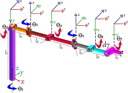
DH parameters [Citation37,Citation38] have been used for kinematic analysis of 7-jointed robot arm.
In , i shows the joint sequence. The lengths are given in metres and the angles are given in degree.
(1)
(1)
(2)
(2)
where iTi+1 is the transfer matrix of link i. 0T7 matrix produces a Cartesian coordinate for any seven joint angles. In Equation (2), Px, Py, and Pz denote the elements of the position vector whereas nx, ny, nz, sx, sy, sz, ax, ay, az denote the rotational elements of the transformation matrix. In this study, only the position vector will be used to calculate the position error. The position vector equation is as follows (where s and c denote the sine and cosine functions):
(3)
(3)
(4)
(4)
(5)
(5)
Table 1. D-H parameters for robot manipulator.
2.2. Model of position error and fitness function
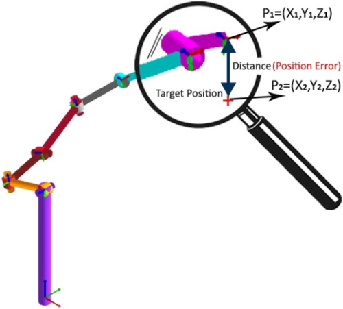
The aim of this study is to obtain the joint angles that will move the end effector to the nearest point to the predetermined position. The Euclid formula which given Equation (6), is used to find the position error that appears in . This equality is also a fitness function which will be used in this study.
(6)
(6)
In order to test the operation of the firefly algorithm, the robot arm is directed to a predetermined position.
Figure 2. Representing the position error.
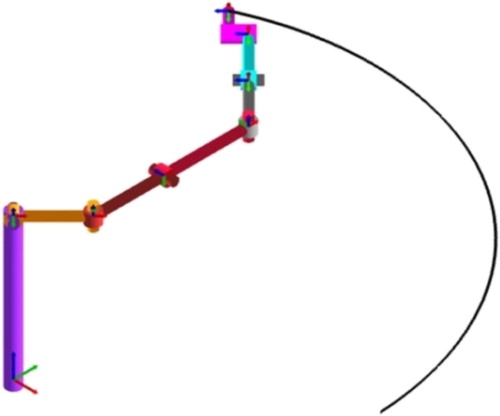
In this study, the defined joints are as follows: Θ1 = 45°, Θ2 = 0°, Θ3 = 45°, Θ4 = 0°, Θ5 = 45°, Θ6 = 0°, Θ7 = 0°. The position of the robot arm which should go through these joints is calculated by firefly algorithm. When the robot arm receives these joints, the end effector will point to a certain position (). The aim of this work is to find the new joints with firefly algorithm, which will position the end element in this determined position.
Figure 3. Determined position of the end effector for this study.
2.3. Firefly algorithm
Firefly Algorithm that was developed by Yang in 2008 [Citation39], is a meta-heuristic and swarm-based optimization method used today to solve the most difficult optimization problems in many areas [Citation40]. At the same time, the FA is part of the group of statistical algorithms since it randomly searches for the solution [Citation41,Citation42].
Firefly Algorithm is based on the social behaviour of fireflies in tropical climate regions. Fireflies produce rhythmic flashing lights to both raise fear on their enemies and to attract other fireflies regardless of their gender to them [Citation41,Citation42]. The less bright fireflies move toward the more brilliant fireflies. So, bright fireflies are always more attractive than others. Therefore, brightness and light intensity are two important variables in this algorithm [Citation43,Citation44]. However, the attractiveness varies according to the position of the firefly. This leads to another variant in the name of the light absorption coefficient [Citation45,Citation46]. To achieve optimal solutions in firefly algorithm: The fitness function of a given optimization problem is related to the intensity of the flashing light or light that helps to go to bright and more attractive places in the firefly's drive [Citation47,Citation48].
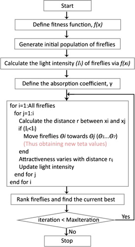
Flowchart of FA Algorithm is shown . The following equation is used for the light intensity which has a decreasing structure as the distance (r) increases (γ; light absorption coefficient, range of values 0.1 and 1):
(7)
(7)
The attractiveness of a firefly is proportional to the light intensity and is found in a formula similar to light intensity, as follow (range of values 0.1 and 1):
(8)
(8)
where β0 is the attractiveness at r = 0. The distance between any two fireflies (xi and xj) is expressed as the Euclidean relationship, as follows:
(9)
(9)
where d is the number of dimension. The movement of firefly i towards the more attractive firefly j is expressed in the following way:
(10)
(10)
Figure 4. Flowchart of firefly algorithm.
This Equation (10) consists of three terms. The first term is the current position of the firefly, the second term is the more attractive firefly, and the last term (α) is a series of varying randomly (α: range of values 0.1 and 1).
Firefly algorithm, which is among the intelligent optimization techniques that are known for producing effective solutions to NP type problems, is widely used in many areas.
3. Simulation results
The main subject of this study is that the optimal angle values of joints are found for the end effector of the robot arm to reach the desired point. The target position of the robot arm can be seen in . Simulations which are number of firefly, minimum position error, computation time and comparison with other techniques have been performed at the Matlab environment. The initial population of the algorithm has been randomly selected at the determined intervals of the joints. In addition, the algorithms have been run ten times and the minimum position error between these values has been considered the best solution. FA parameters are used as follows: α: 0.3, γ: 0.9 and β: 0.9.
Although one of the most important features of the swarm algorithms is the better solution as the number of particles increases, this solving time also increases. In this study, inverse kinematic calculations were performed with 30, 40, 50, 60, 70, 80 and 90 fireflies and the results are shown in .
Table 2. Particle number, computation time and position error simulation results.
As a result of the tests made, the joint angles appearing in indicate that the end effector of the robot manipulator reaches the desired point with minimum error. It is clear that the value of joints is different in all tests due to the infinite number of solutions of redundant manipulators.
Table 3. The angle of the joints obtained by the number of particles.
The obtained joint angles reach the end effector of the robot manipulator to a certain point in the work space. The x, y, z coordinates of this point are shown in .
Table 4. Positions of the end effector in work space.
According to swarm numbers, the position errors calculated using the joint angles obtained with the firefly technique is shown in . It is obvious that the increase in the number of firefly has helped the solution to be in the best condition.
Figure 5. Solving contribution of swarm numbers.
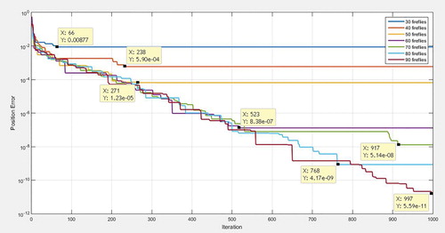
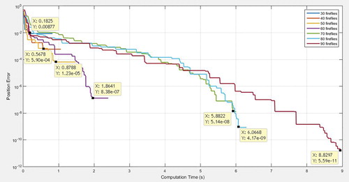
Although the algorithms were terminated at 1000 iterations, the solution could not be improved after a certain value. This value is considered to be the best solution for the algorithm and is also shown in Figures and . The increase in the number of swarm makes it possible to obtain a better solution, but it is moving up to the top of the computation time ().
Figure 6. The graphic of computation time and position error.
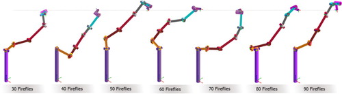
It has been emphasized earlier in this work that the inverse kinematic solution set of a 7-DOF redundant manipulator is an infinite number of elements. This situation is obvious in . Here, the final positions of the manipulator have been revealed in the RoboAnalyzer [Citation49] interface through the joint angles obtained with each firefly swarm. When the literature search is done in the inverse kinematic solution, it is used in artificial bee colony and particle swarm optimization as well as firefly algorithm.
Figure 7. Final position of the 7-DOF manipulator according to the number of firefly.
In this study, the joint angles obtained with these algorithms are shown in . Since the firefly algorithm works based on a swarm optimization technique, it is of course important to compare it with other swarm algorithms. The comparison was made according to the execution time and the number of iterations to reach the solution and it was illustrated in two different graphs. Each algorithm was run 10 times and the smallest position error was obtained as the best solution.
Table 5. Comparative results of other techniques.
shows the computation times of all three algorithms. ABC and PSO techniques completed 500 iterations around 0.7 and 0.9 s, but the best solution reached 0.45 s. However, the firefly algorithm has the longest run time in terms of completing both 500 iterations and reaching the best solution. These times are 11 and 0.9 s.
Figure 8. The graphic of computation time [Citation50].
![Figure 8. The graphic of computation time [Citation50].](/cms/asset/44b1a0bb-6375-46b8-88d8-9911e1516723/gipe_a_1602124_f0008_oc.jpg)
illustrates the position error comparisons of the algorithms. In terms of both the minimum position error value and the number of iterations that the solution reaches, the technique with the worst solution among these three algorithms is PSO. However, from this point of view, the best solution values were obtained by the firefly algorithm.
Figure 9. The graphic of position error (cm) and iteration [Citation50].
![Figure 9. The graphic of position error (cm) and iteration [Citation50].](/cms/asset/c7b0e800-1a38-4b06-a3ed-f126410c40b9/gipe_a_1602124_f0009_oc.jpg)
4. Conclusion
In this study, the inverse kinematics solution, that is the most difficult problem group, is calculated by using firefly algorithm which is one of the recent popular optimization techniques. Simulation results show that the firefly algorithm has been yield very successful data. As the size of the swarm grew, both the quality of the solution and the calculation time has increased. Therefore, it seems that swarm size is an important parameter in swarm-based optimization algorithms. So, this algorithm can be used in very sensitive work in which it is more important that the work is done rather than the importance of the solution time and it can also be used for tasks that need to be done in a short period of time. It is obvious that the firefly algorithm produces better solutions between 10 times and 10,000 times than other swarm algorithms in the tests made. When compared with other techniques in terms of computation time, it can be said that the solution is reached in relatively short time. As a result, the firefly algorithm which can produce effective results in the most complex problems has proved successful in the inverse kinematic solution of a redundant robot arm.
Disclosure statement
No potential conflict of interest was reported by the authors.
References
- Yang XS, He X. Firefly algorithm: recent advances and application. Int J Swarm Intell. 2013;1:36–50. doi: 10.1504/IJSI.2013.055801
- Dereli S, Köker R. In a research on how to use inverse kinematics solution of actual intelligent optimization method. In Proceeding of the International Symposium on Innovative Technologies in Engineering and Science, ISITES; 2016.
- Chyan GS, Ponnambalam SG. Obstacle avoidance control of redundant robots using variants of particle swarm optimization. Robot Comput Integr Manuf. 2012;28:147–153.
- Harrison KR, Engelbrecht AP, Ombuki-Berman BM. Inertia weight control strategies for particle swarm optimization. Swarm Intell. 2016;10:367–305. doi: 10.1007/s11721-016-0128-z
- Karaboğa D, Gorkemli B, Ozturk C, et al. A comprehensive survey: artificial bee colony (ABC) algorithm and applications. Artif Intell Rev. 2014;42:21–57. doi: 10.1007/s10462-012-9328-0
- Gao W, Liu S. Improved artificial bee colony algorithm for global optimization. Inf Process Lett. 2011;111:871–882. doi: 10.1016/j.ipl.2011.06.002
- Dorigo M, Stützle T. Ant colony optimization: Overview and recent advances. In: Handbook of metaheuristics. Cham: Springer; 2019. p. 311–351.
- Albinati J, Oliveira SEL, Otero FEB, et al. An ant colony-based semi-supervised approach for learning classification rules. Swarm Intell. 2015;9:315–341. doi: 10.1007/s11721-015-0116-8
- Karaboğa D, Akay B. A servey: algorithms simulating bee swarm intelligence. Artif Intell Rev. 2009;31:61–85. doi: 10.1007/s10462-009-9127-4
- Gao W, Liu S, Huang L. A global best artificial bee colony algorithm for global optimization. J Comput Appl Math. 2012;236:2741–2753. doi: 10.1016/j.cam.2012.01.013
- Das PK, Behera HS, Panigrahi BK. A hybridization of an improved particle swarm optimization and gravitational search algorithm for multi-robot path planning. Swarm Evol Comput. 2016;28:14–28. doi: 10.1016/j.swevo.2015.10.011
- Amador-Angulo L, Mendoza O, Castro JR, et al. Fuzzy sets in dynamic adaptation of parameters of a bee colony optimization for controlling the trajectory of an autonomous mobile robot. Sensors. 2016;16:1–27. doi: 10.3390/s16091458
- Reid CR, Latty T. Collective behaviour and swarm intelligence in slime moulds. FEMS Microbiol Rev. 2016;40:798–806. doi: 10.1093/femsre/fuw033
- Zhang L, Liu L, Yang XS, et al. A novel hybrid firefly algorithm for global optimization. Plos One. 2016;9:1–17.
- Yang XS. Nature-inspired metaheuristic algorithms, firefly algorithm. London: Luniver Press; 2010. p. 63–73.
- Chakraborty A, Kar AK. Swarm intelligence: a review of algorithms. Nature-inspired computing and optimization. Cham: Springer; 2017. p. 488–495.
- Mavrovouniotis M, Li C, Yang S. A server of swarm intelligence for dynamic optimization: algorithm and application. Swarm Evol Comput. 2017;33:1–17. doi: 10.1016/j.swevo.2016.12.005
- Blum C, Grob R. Swarm intelligence in optimization and robotics. Handbook of Computational intelligence. Berlin: Springer; 2015.
- Rokbani N, Alimi AM. Inverse kinematics using particle swarm optimization, a statistical analysis. In Proceeding of the International Conference on Design and Manufacturing; 2013. p. 1602–1611.
- Çavdar T, Mohammed M, Milani RA. A new heuristic approach for inverse kinematics of robot arms. Adv Sci Lett. 2013;19:329–333. doi: 10.1166/asl.2013.4700
- Savsani PV, Jhala RL. Optimal motion planning for a robot arm by using artificial bee colony (ABC) algorithm. Int J Mod Eng Res (IJMER). 2012;2:4434–4438.
- Masajedi P, Shirazi KH, Ghanbarzadeh A. Verification of bee algorithm based path planning for a 6-DOF manipulator using ADAMS. J Vibroeng. 2013;15:805–815.
- Kolling A, Walker P, Chakraborty N, et al. Human interaction with robot swarms: A survey. IEEE Trans Hum Mach Syst. 2016;46:9–26. doi: 10.1109/THMS.2015.2480801
- Ni J, Wu L, Fan X, et al. Bioinspired intelligent algorithm and its applications for mobile robot control: a survey. Comput Intell Neurosci. 2016;2016:1–16. doi: 10.1155/2016/3810903
- Kucuk S. Energy minimization for 3-RRR fully planar parallel manipulator using particle swarm optimization. Mech Mach Theory. 2013;62:129–149. doi: 10.1016/j.mechmachtheory.2012.11.010
- Parhi DR. Advancement in navigational path planning of robots using various artificial and computing techniques. Int Rob Auto J. 2018;4:133–136.
- Köker R, Çakar T. A neuro-genetic-simulated annealing approach to the inverse kinematics solution of robots: a simulation based study. Eng Comput. 2016;32:553–565. doi: 10.1007/s00366-015-0432-z
- Serrano ME, Godoy SA, Quintero L, et al. Interpolation based controller for trajectory tracking in mobile robots. J Intell Rob Syst. 2017;86:569–581. doi: 10.1007/s10846-016-0422-4
- Geisert M, Mansard N. Trajectory generation for quadrotor based systems using numerical optimal control. In 2016 IEEE International Conference on Robotics and Automation (ICRA); 2016. p. 2958–2964. IEEE.
- Zhang L, Xiao N. A novel artificial bee colony algorithm for inverse kinematics calculation of 7-DOF serial manipulators. Soft Comput. 2017:1–9. doi:10.1007/s00500-017-2975-y
- Mahanta GB, Deepak BBVL, Dileep M, et al. Prediction of inverse kinematics for a 6-DOF Industrial robot Arm using soft computing techniques. In: Soft computing for problem solving. Singapore: Springer; 2019. p. 519–530.
- Rokbani N, Casals A, Alimi AM. IK-FA, a new heuristic inverse kinematics Solver using firefly algorithm. Comput Intell Appl Model Control. 2015;575:369–395.
- El-Sherbiny A, El-Hosseini MA, Haikal AY. A new ABC variant for solving inverse kinematics problem in 5 DOF robot arm. Appl Soft Comput. 2018;73:24–38. doi: 10.1016/j.asoc.2018.08.028
- Ayyıldız M, Çetinkaya K. Comparison of four different heuristic optimization algorithms for the inverse kinematics solution of a real 4-DOF serial robot manipulator. Neural Comput Appl. 2016;27:825–836. doi: 10.1007/s00521-015-1898-8
- Dereli S, Köker R. Iw-PSO approach to the inverse linematics problem solution of a 7-DOF serial robot manipulator. Sigma. 2018;36:77–85.
- Ferrentino E, Chiacchio P. Topological analysis of global inverse kinematic solutions for redundant manipulators. In: ROMANSY 22–robot design, dynamics and control. Cham: Springer; 2019. p. 69–76.
- Iliukhin VN, Mitkovskii KB, Bizyanova DA, et al. The modeling of inverse kinematics for 5 DOF manipulator. Procedia Eng. 2017;176:498–505. doi: 10.1016/j.proeng.2017.02.349
- Serrezuela RR, Chavarro AFC, Cardozo MAT, et al. Kinematic modeling of a robotic arm manipulator using Matlab. ARPN J Eng Appl Sci. 2017;12:2037–2045.
- Yang XS. Firefly algorithm. Nature-inspired metaheuristic algorithm. Luniver Press; 2008. p. 79–90.
- Wang H, Wang W, Zhou X, et al. Firefly algorithm with neighborhood attraction. Inf Sci (Ny). 2017;382:374–387. doi: 10.1016/j.ins.2016.12.024
- Fister I, Yang XS, Brest J. A comprehensive review offirefly algorithms. Swarm Evol Comput. 2013;13:34–46. doi: 10.1016/j.swevo.2013.06.001
- Wang H, Cui Z, Sun H, et al. Randomly attracted firefly algorithm with neighborhood search and dynamic parameter adjustment mechanism. Soft Comput. 2017;21:5325–5339. doi: 10.1007/s00500-016-2116-z
- Patle BK, Pandey A, Jegadeesh A, et al. Path planning in uncertain environment by using firefly algorithm. Defence Technol. 2018;14:691–701. doi: 10.1016/j.dt.2018.06.004
- Wang H, Zhou X, Sun H, et al. Firefly algorithm with adaptive control parameters. Soft Comput. 2017;21:5091–5102. doi: 10.1007/s00500-016-2104-3
- Pal SK, Rai CS, Singh AP. Comparative study of firefly algorithm and particle swarm optimization for noisy non-linear optimization problems. Intell Syst Appl. 2012;10:50–57.
- Patle BK, Parhi DR, Jagadeesh A, et al. On firefly algorithm: optimization and application in mobile robot navigation. World J Eng. 2017;14:65–76. doi: 10.1108/WJE-11-2016-0133
- Wang H, Cui Z, Sun H, et al. Randomly attracted firefly algorithm with neighborhood search and dynamic parameter adjustment mechanism. Soft Comput. 2016;20:1–15. doi: 10.1007/s00500-015-1933-9
- Yang XS. Firefly Algorithm, Lévy Flights and Global Optimization. Research and Development in Intelligent Systems XXVI. London: Springer; 2010. p. 209–218.
- Gupta V, Chittawadigi RG, Saha SK. (2017, June). RoboAnalyzer: robot visualization software for robot technicians. In Proceedings of the Advances in Robotics (p. 26). ACM.
- Dereli S, Köker R. A meta-heuristic proposal for inverse kinematics solution of 7-DOF serial robotic manipulator: quantum behaved particle swarm algorithm. Artifi Intell Rev. 2019; 1–16. doi:10.1007/s10462-019-09683-x