
ABSTRACT
Introduction
Steering light is relevant to many medical applications that require tissue illumination, sensing, or modification. To control the propagation direction of light beams, a great variety of innovative fiber-optic medical devices have been designed.
Areas covered
This review provides a comprehensive overview of the patent literature on light beam control in fiber-optic medical devices. The Web of Science Derwent Innovation Index database was scanned, and 81 patents on fiber-optic devices published in the last 20 years (2001–2021) were retrieved and categorized based on the working principle to steer light (refraction/reflection, scattering, diffraction) and the design strategy that was employed (within fiber, at fiber end, outside fiber).
Expert opinion
Patents describing medical devices were found for all categories, except for generating diffraction at the fiber end surface. The insight in the different designs reveals that there are still several opportunities to design innovative devices that can collect light at an angle off-axis, reduce the angular distribution of light, or split light into multiple beams.
1. Introduction
1.1. Background
Optical fibers are commonly integrated into medical devices for remote light delivery and collection because of their high flexibility, low propagation loss, compatibility, and tolerance to electromagnetic interference [Citation1]. The usefulness of fiber-optic devices has been shown for various medical applications, such as temperature, pressure and shape sensing [Citation2–7], tissue illumination and modification [Citation8–10], and spectral tissue sensing [Citation8–10]. A conventional optical fiber is made up of a core that carries the light, a cladding, and a buffer coating. The refractive index of the cladding is slightly lower than the refractive index of the core. Because of this difference in refractive index, light incident on the core-cladding interface with an angle greater than a certain threshold, known as the critical angle, is reflected back into the core – a phenomenon known as total internal reflection. Thanks to total internal reflection, light can travel along the longitudinal axis of the optical fiber core to the distal end of a device.
When using fiber-optic medical devices for illumination, spectral tissue sensing, and cell modification, the light leaves the distal end of the device and interacts with the surrounding tissue. The optical characteristics and shape of the distal end determine how light is emitted to or collected from tissue [Citation9,Citation11]. A conventional distal end design is a flat polished fiber tip [Citation11]. As light leaves and enters the distal end of the device in axial direction, the utility of such a conventional fiber-optic device is limited.
Modified distal end designs for light beam control could have great potential to expand the range of possible applications, for example: emitting and collecting light at an angle off-axis allows for side-looking tissue spectroscopy, improved laser ablation and tissue welding; the angular distribution of light can be increased for uniform irradiation as required in photodynamic therapy or for photodisinfection or, on the contrary, decreased for beam focusing in laser surgery; finally, splitting light into multiple beams allows for multi-spot pattern generation as required in laser photocoagulation. For these applications, new fiber-optic devices are needed that can control the propagation direction of light beams and steer them as desired to meet various challenges:
emit light at an angle off-axis;
collect incident light at an angle off-axis;
increase the angular distribution of light;
decrease the angular distribution of light;
split light into multiple beams.
1.2. Goal and structure
This review provides a comprehensive overview of the patent literature on light beam control in medical devices. It investigates how various distal end designs can steer light in the desired direction and identifies new design challenges in this field of research. All selected patents are categorized based on the underlying working principle to steer light and the employed design strategy to incorporate this principle into the distal end of a fiber-optic medical device to provide insights into future technological directions for the identification of new design challenges for steering light. Section 2 reports the method of the patent search and the search results. Section 3 explains the categorization of the fiber-optic devices. Section 4 treats the different distal end designs found for devices employing refraction and reflection. Section 5 treats the different distal end designs found for devices employing scattering. Section 6 treats the different distal end designs found for devices employing diffraction. The types of distal end designs and their effect on the light beam propagation direction are discussed in relation to the temporal distribution of the categorized patents in Section 7. Finally, Section 8 provides the conclusion, and Section 9 presents our expert commentary on this topic.
2. Method
2.1. Patent search method
A patent search was conducted on distal end designs of fiber-optic medical devices for remote light delivery and collection, using the Web of Science Derwent Innovation Index (DII) patent database. The search query consisted of a logical conjunction (AND) of keywords in two categories: object (targeting devices including a light guide for remote light delivery and collection) and location (targeting patents describing specifically the distal end of fiber-optic devices). The patent search was not restricted to devices with one specific function; however, a combination of keywords within a third category, imaging applications (targeting imaging devices disposing of complex optical systems for light beam focusing), was added to the search query as a logical complement (NOT) to exclude patents irrelevant to this review. Moreover, the search query was limited within classification P3: Health and amusement, levels P31-P34. These levels of the DII classification system are comparable with classification A61: Medical or veterinary science; hygiene of the general cooperative patent classification (CPC). The search was restricted to patents linked to the World Intellectual Property Organization (WO*), the United States (US*), or Europe (EP*), published within the last 20 years. The entire search query was: TI = ((light* OR laser* OR optic*) AND (fiber* OR *guide OR probe OR needle OR delivery)) AND TI = (end OR distal OR tip OR exit OR aperture) AND DC = (P31 OR P32 OR P33 OR P34) AND PN = (WO* OR US* OR EP*) NOT TI = (imag* OR tomograph* OR scan* OR camera OR microscop*) Timespan: 2001–2021.
2.2. Eligibility criteria
The search was restricted to devices for use inside the body with direct light-tissue interaction for illumination, spectral tissue sensing, or cell modification via laser surgery or light-induced therapy. The following eligibility criteria were applied:
application domain: patent describes an optical fiber for remote light delivery or collection in the human body
function: light directly interacts with tissue for illumination, spectral tissue sensing, or cell modification
direction control: patent describes an optical feature at the distal end of the device that steers light in the desired direction
language: patent is available in English
2.3. Patent search results
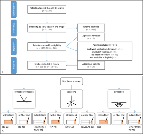
The patent search query returned 1197 patents from the DII database (last update 1 December 2021). The titles, abstracts, and figures of these patents were manually checked based on the eligibility criteria. All criteria need to be fulfilled for the patent to be included in the review. This selection resulted in 166 patents being potentially useful. All search results from the DII database included a link to the Espacenet database, which allows for users to access the complete text. The full text of the 166 potentially valuable patents was further examined by reading the patents’ claims and descriptions, and by in-depth analysis of the figures. After checking these patents, 15 duplicates were identified, and 84 patents were excluded. The final selection resulted in 67 relevant patents. For all relevant patents, the cited patents were scanned for new relevant information, resulting in 14 additional patents that met all of the criteria. Finally, 81 patents were included in this review, see .
Figure 1. a Schematic representation of the patent selection method. b Distal end designs of fiber-optic medical devices that can steer light in the desired direction, categorized based on the working principle to steer light (Level 1) and the design strategy that was employed (Level 2). References are given in brackets.
3. Categorization
There are four working principles for steering a light beam in the desired direction [Citation12]
refraction;
reflection;
scattering;
diffraction.
Refraction is defined as the change in direction of a transmitted light beam after it enters a second medium. Reflection is defined as the change in direction of a light beam at an interface that returns the light beam back to the original medium. The angle of incidence of the light beam on the surface and the material properties of the two media determine the intensity and direction of the refracted and reflected light beam. Another way to steer light is scattering: multiple changes in refractive index force the light beam to randomly change direction in a series of reflection events, resulting in diffuse light scattering. Lastly, a fundamentally different method to steer a light beam is diffraction. Diffraction is defined as the bending of light after encountering a small opening or obstacle. The light beam does not bend in one direction; instead, a diffraction pattern is generated by the interference of different wave fronts. Diffraction is predominant for apertures and obstacles with sizes in the range of the wavelength of the incident light.
For refraction and reflection, an interface between two media is required; for scattering, a volume causing many reflection events is required; for diffraction, a small aperture or obstruction is required. Within a fiber-optic medical device, these design requirements can be met by changing the geometry or material of the optical fiber core and cladding, resulting in a change in the total internal reflection pattern within the fiber itself. Another option is changing the shape and material properties of the optical fiber core end surface. Finally, a regular optical fiber can be used with an extra optical element added outside the fiber. In summary, there are three design strategies for steering a light beam in the desired direction:
modifying the total internal reflection pattern inside the optical fiber;
modifying the optical fiber core end surface;
adding an optical element outside the optical fiber.
Hence, all distal end designs of the fiber-optic medical devices included in this review are categorized based on the working principle to steer light (Level 1) and the design strategy that was employed (Level 2), see . Some patents describe various designs for achieving light beam steering using the same underlying working principle. Likewise, one device can include multiple optical features to steer the light in the desired direction using different underlying working principles. Therefore, a single patent can be assigned to multiple categories.
4. Refraction and reflection
4.1. Modifying the total internal reflection pattern inside the optical fiber
Ten patents describe devices with customized distal ends that use the existing interface between the core and the cladding within an optical fiber to steer light in the desired direction [Citation13–22]. Usually, the longitudinal axis of an optical fiber within a medical device is parallel to the longitudinal axis of the device itself. However, fiber-optic medical devices can have one or more optical fibers with a bent distal section inserted into a curved path within the housing of the device [Citation13–18]. The total internal reflection of light along the bent section enables light to leave or enter the optical fiber at an angle off the device’s longitudinal axis. In other words, the bent segment generates a fiber terminating tip that faces the side. The most basic designs use one optical fiber, which is curved away from the central axis to emit light to the side, see [Citation13–15]. Kern et al. [Citation16] describe a unique design where the fiber is first curved away from the central axis and then curved toward it to achieve a larger curve radius. Two other patented devices include distal end designs with numerous bent optical fibers, one or more of which emit light and one or more of which collect light [Citation17,Citation18].
Figure 2. Distal end designs of fiber-optic medical devices to steer a light beam toward the tissue with refraction and reflection. In the design sketches, blue lines delimitate the fiber core; dashed red lines indicate the center of the light beam within the fiber; red arrows indicate the light leaving the fiber. a Bent fiber with path curved away from the central axis of the device (adapted from [Citation14]). b Twisted fibers in six-around-one configuration (adapted from [Citation20]). c Fiber with removed fiber cladding (Orange) that forms a side-facing tip (adapted from [Citation21]). d Fiber tip with slanted core end surface with reflected (bright red) and refracted (dark red) light beam (adapted from [Citation24]). e Fiber tip with cone-shaped core end surface (adapted from [Citation40]). f Fiber tip with multiple slanted surfaces in axial direction (adapted from [Citation46]). g Fiber with micro-sphere coating (pink) at core end surface (adapted from [Citation48]). h Distal tip (green) with slanted surface (pink) (adapted from [Citation49]). i Distal tip (green) with varying bevel reflecting surface (pink) (adapted from [Citation55]). j Distal tip (green) with semi-spherical lens (pink) (adapted from [Citation49]). k Fiber with prism (pink) (adapted from [Citation66]).
![Figure 2. Distal end designs of fiber-optic medical devices to steer a light beam toward the tissue with refraction and reflection. In the design sketches, blue lines delimitate the fiber core; dashed red lines indicate the center of the light beam within the fiber; red arrows indicate the light leaving the fiber. a Bent fiber with path curved away from the central axis of the device (adapted from [Citation14]). b Twisted fibers in six-around-one configuration (adapted from [Citation20]). c Fiber with removed fiber cladding (Orange) that forms a side-facing tip (adapted from [Citation21]). d Fiber tip with slanted core end surface with reflected (bright red) and refracted (dark red) light beam (adapted from [Citation24]). e Fiber tip with cone-shaped core end surface (adapted from [Citation40]). f Fiber tip with multiple slanted surfaces in axial direction (adapted from [Citation46]). g Fiber with micro-sphere coating (pink) at core end surface (adapted from [Citation48]). h Distal tip (green) with slanted surface (pink) (adapted from [Citation49]). i Distal tip (green) with varying bevel reflecting surface (pink) (adapted from [Citation55]). j Distal tip (green) with semi-spherical lens (pink) (adapted from [Citation49]). k Fiber with prism (pink) (adapted from [Citation66]).](/cms/asset/82d93dc4-398b-46b3-b3a0-3ba407228524/ierd_a_2054334_f0002_oc.jpg)
It is also possible to twist several optical fibers around the central axis of the device [Citation19,Citation20]. As described by Farley [Citation19], several fibers can be twisted to form a helix, with the terminating tips of all optical fibers being angularly separated. This produces a multi-spot pattern of light on the target tissue. Cottrel and Foster [Citation20] describe a device that can both emit and collect light from the side using twisted optical fibers. This device includes seven optical fibers in a six-around-one configuration. The six outside fibers are twisted into side-fire fibers and arranged along the device’s longitudinal axis in a linear array. At least one of the optical fibers acts as a light source, while the other fibers collect the light after interaction with the tissue, see .
Instead of bending the optical fiber, it is also possible to remove the material of the cladding at the distal section of the fiber to generate a side-facing tip [Citation21,Citation22]. The slot within the cladding generates an interface where light does not reflect entirely, allowing it to exit the fiber in radial direction. Multiple slots in the optical fiber allow light to leave at multiple locations along the length of the fiber, see .
4.2. Modifying the optical fiber core end surface
Twenty-six patents describe devices with a modified optical fiber core end surface [Citation23–48]. The core end surface is the distal end of the core where the light beam leaves or enters the fiber. Different core end surface designs can cause different light propagation patterns.
Fifteen patents describe distal end designs including optical fibers with a slanted core end surface [Citation23–37]. When light reaches the fiber tip, it is redirected by the slanted core end surface, causing light to leave or enter the optical fiber at an angle relative to the device’s longitudinal axis. Depending on the angle and material properties of the slanted surface, which vary among devices, the light beam can be reflected or refracted, see . A standard design includes one optical fiber with a slanted core end surface. This surface creates an interface between optical fiberglass, typically silica, and a tissue region [Citation23,Citation24]. Because of the slanted fiber tip, light approaches the surface at an oblique angle to the surface normal and refracts into the tissue, leaving the device at a small angle to its longitudinal axis. A reflective coating can be applied to the surface to generate reflection, and thereby increase the emitting angle [Citation25–31]. A reflective coating can be a metal coating or a multilayer dielectric coating. Another method to generate a reflective surface at the slanted fiber tip is by adding a thin layer of air between a beveled tip of a light delivery fiber and a short stub fiber [Citation32]. Total internal reflection occurs at the interface between the fiber core and the air layer because the refractive index of air is significantly lower than that of the optical fiber core. More advanced designs include multiple optical fibers with slanted surfaces that can emit light toward the tissue and collect light from the tissue [Citation33–37]. The emitting and collecting fibers’ core end surfaces can be in the same cross-sectional plane [Citation33,Citation37] or separated in longitudinal direction to increase the distance between various core end surfaces [Citation34–37]. The device described by Huang et al. [Citation33] contains a slanted collecting fiber tip without a reflective coating. Therefore, light is collected from the tissue at a small angle to the device’s longitudinal axis. The other devices contain a reflective slanted surface to enable light delivery to and collection from tissue off-axis.
Another possible fiber core end design is a conical shape as described in seven patents [Citation23,Citation38–43]. The cone can be polished either positively [Citation23,Citation38–41] or negatively [Citation42,Citation43]. For a standard positively polished tip, the conical surface forms an interface between two media: fiberglass and tissue [Citation23,Citation38–40]. Most light rays that strike the cone wall for the first time reflect totally, as their incidence angle is greater than the critical angle. These reflected light rays then strike the opposing wall of the cone with an incident angle lower than the critical angle, causing radial refraction of the light beam into the tissue, see . The device of Scheller [Citation41] describes a unique positively polished cone-shaped fiber tip design with four slanted surfaces that split the light into four separate beams that travel in individual directions. Two devices include a design for a negatively polished tip [Citation42,Citation43]. This surface always contains a reflective coating that ensures that all light that strikes the cone is reflected into the tissue [Citation42,Citation43] or collected from the tissue [Citation43] in radial direction.
Four patents describe distal end designs with specifically shaped core end surfaces [Citation44–47] that enable light to leave the optical fiber in axial and radial direction. In these devices, the fiber core end includes a series of slanted or cone-shaped surfaces. The light incident on these surfaces is reflected or refracted into the tissue in radial direction, see .
Lastly, Auld [Citation48] describes a special fiber core end surface. In this device, the fiber tip is a conventional flat polished surface perpendicular to the fiber’s longitudinal axis. However, a coating with a monolayer of hollow glass microspheres is attached to the core end surface. These microspheres provide a significant change in refractive index by the glass-air-glass interface. The light beam entering these spheres refracts four times, resulting in light being emitted into the tissue with a wide angular distribution, see .
4.3. Adding an optical element outside the optical fiber
Twenty-three patents describe distal end designs that redirect light by an optical element outside the optical fiber [Citation26,Citation29,Citation33,Citation34,Citation39,Citation49–66]. In these devices, light exits the optical fiber in axial direction and propagates into an additional distal tip of the medical device (said to be coupled to the distal end of the optical fiber). For example, this can be done by affixing the distal tip to the distal end of the buffer layer of the optical fiber [Citation49] or to the stripped fiber core [Citation29]. The body of the distal tip can consist of various bio-compatible and transparent materials. The distal tip can include different optical elements.
Eleven patents describe designs including one or more reflective surfaces fixed within an additional distal tip [Citation29,Citation34,Citation39,Citation49–56]. In four of these devices, the distal tip has one single inclined reflective surface that is optically coupled to one optical fiber and redirects light off the fiber axis into the tissue [Citation29,Citation49–51], see . This surface can consist of various materials such as polymer, glass, metal, or ceramic. To decrease leakage of light in undesired directions, it can have a metal or dielectric coating, or it can be entirely made of a highly reflective metal such as gold or silver. Alternatively, it is possible to create a highly reflective surface by adding an air cavity behind an inclined surface made of glass [Citation51]. In three devices, the reflective surface coupled to one optical fiber can have a conical shape [Citation39,Citation52], directing light into the tissue in radial direction, or a curved shape [Citation53], converging or diverging the light rays. In two patents, one single reflective surface is coupled to multiple optical fibers [Citation54,Citation55], allowing for light delivery to and collection from tissue off-axis. After exiting an optical fiber, light is redirected off the fiber axis into the tissue by a reflecting surface, and the scattered light from the tissue is redirected back into another optical fiber by the same reflective surface. The reflective surface can be convex [Citation55], straight inclined [Citation54], or step-wise inclined [Citation55], see . In two more patents, multiple reflective surfaces are separately linked to individual optical fibers [Citation34,Citation56]. These devices are also used to emit and collect light at an angle off-axis.
Another optical component that can be added outside the optical fiber to steer a light beam is a lens, as described in twelve patents [Citation26,Citation33,Citation57–66]. A lens redirects a light beam due to refraction, changing its angular distribution. Lenses can be divided into converging and diverging lenses. In six devices, the distal tip includes a converging lens [Citation26,Citation33,Citation57–60]. These converging lenses can be semi-spherical [Citation57,Citation58] or convex lenses [Citation26,Citation33,Citation58–60]. In most standard designs, a converging lens focuses a light beam on a specific tissue area [Citation26,Citation33,Citation57–60], see . The same converging lens can also collect light from this specific tissue area to one or more collecting fibers [Citation33,Citation57]. Smith [Citation60] describes a special design including a converging lens and a faceted surface. The faceted surface receives light from the optical fiber and refracts it into different beam elements, which are then focused into multi-spots by a convex lens. In six devices, the distal tip includes a diverging lens [Citation61–66]. This can be a semi-spherical [Citation61–63], gradient-index [Citation64], or concave [Citation65] lens. Diverging lenses illuminate a wide area in the tissue. Nagale et al. [Citation66] describe a special type of diverging lens, which is a triangular prism. The distal tip of this device consists solely of a prism that is directly coupled to the optical fiber. A light beam entering the prism refracts at the first face and then refracts again at the second face. As a result, light is emitted radially with a wide angular distribution. The prism can also rotate, allowing light to be emitted into the tissue in a 360° range, see .
5. Scattering
5.1. Modifying the total internal reflection pattern inside the optical fiber
Devices that diffusely scatter light into the tissue by special features within the core or cladding of the fiber are described in seven patents [Citation67–73]. In all of these devices, light is redirected within an optical fiber through scattering events caused by multiple changes in the refractive index. The scattering causes light to strike the interface between the core and the cladding from various angles. The angle can be lower than the critical angle for total internal reflection, resulting in diffuse light exiting the optical fiber in radial direction along its length. In a simple design, a scattering region containing scattering particles [Citation67,Citation68] or nanovoids [Citation69] is incorporated into the distal section of the optical fiber core. Examples of scattering particles that can be embedded within the optical fiber core are titania or silica. Nanovoids are small bubbles that can be formed, for example, by focusing a high-power laser on an optical fiber. Because the refractive index of both particles and nanovoids is different from that of the host medium, they generate scattering events, see . Luloh et al. [Citation70] describe a device with an entire core made of translucent instead of transparent material. The changes in refractive index within the translucent material cause scattering events all along the core.
Figure 3. Distal end designs of fiber-optic medical devices to steer a light beam toward the tissue with scattering. In the design sketches, blue lines delimitate the fiber core; dashed red lines indicate the center of the light beam within the fiber; red arrows indicate the light leaving the fiber. a Fiber with scattering particles (black dots) within fiber core (adapted from [Citation69]). b Fiber with scattering particles (black dots) within cladding (Orange) (adapted from [Citation71]). c Fiber including distorted scattering regions (yellow) (adapted from [Citation73]). d Fiber tip with sphere-shaped core end surface (adapted from [Citation74]). e Fiber tip with rough, cone-shaped fiber core end surface (adapted from [Citation75]). f Diffuser tip with conical region (green) including scattering particles (black dots) (adapted from [Citation80]). g Diffuser tip (green) including scattering particles (black dots) and reflector surface (pink) (adapted from [Citation84]). h Diffuser tip with multiple reflective surfaces (green) (adapted from [Citation87]).
![Figure 3. Distal end designs of fiber-optic medical devices to steer a light beam toward the tissue with scattering. In the design sketches, blue lines delimitate the fiber core; dashed red lines indicate the center of the light beam within the fiber; red arrows indicate the light leaving the fiber. a Fiber with scattering particles (black dots) within fiber core (adapted from [Citation69]). b Fiber with scattering particles (black dots) within cladding (Orange) (adapted from [Citation71]). c Fiber including distorted scattering regions (yellow) (adapted from [Citation73]). d Fiber tip with sphere-shaped core end surface (adapted from [Citation74]). e Fiber tip with rough, cone-shaped fiber core end surface (adapted from [Citation75]). f Diffuser tip with conical region (green) including scattering particles (black dots) (adapted from [Citation80]). g Diffuser tip (green) including scattering particles (black dots) and reflector surface (pink) (adapted from [Citation84]). h Diffuser tip with multiple reflective surfaces (green) (adapted from [Citation87]).](/cms/asset/f8833c0c-0bc4-45a4-8522-d74a8674b842/ierd_a_2054334_f0003_oc.jpg)
A device can also have a scattering region within the optical fiber cladding, as described in two patents [Citation71,Citation72]. In the device of Skutnik [Citation71], a region of the cladding consists of a nanoporous structure including scattering particles, which can be diamond dust, titania, alumina, powdered sapphire, powdered zirconia, or powdered quartz, see . In the device of Mersch [Citation72], a region of the cladding consists of multiple rough surfaces.
Lastly, a distal end design can include a scattering region that is formed by distorting part of the optical fiber core and cladding [Citation73]. A deformation pattern is created in parts of the optical fiber by a series of controlled tension, heating, elongation and cooling cycles. This deformation pattern generates light scattering within the distorted regions, see .
5.2. Modifying the optical fiber core end surface
Three patents describe distal ends with a redesigned optical fiber core end surface that diffusely scatters light into the tissue [Citation70,Citation74,Citation75]. A transparent spherical portion can be formed at the fiber tip [Citation70,Citation74]. Before the light beam refracts into the tissue, the curved surface of the spherical portion evokes several reflection events through total internal reflection. Due to the many reflection events of separate light rays, light scatters in multiple directions, enabling wide dispersion of light into the tissue, see .
Another approach to diffuse light is to create a rough fiber core end surface: Hamada [Citation75] describes a cone-shaped fiber tip design with a rough surface finish that generates light scattering due to light interaction with the irregularities on the rough surface, see .
5.3. Adding an optical element outside the optical fiber
Sixteen patents describe devices that achieve light scattering by a separate diffuser tip joined to the distal end of an optical fiber [Citation67,Citation68,Citation76–89]. Light leaves the optical fiber core in axial direction and enters the diffuser tip.
Thirteen devices describe a diffuser tip that consists of a transparent host medium including scattering particles [Citation67,Citation68,Citation76–86]. The host medium can be composed of polymeric materials such as epoxy, polyurethane, or similar materials. Scattering particles used in diffuser tips are alumina, silica, or titania. The most basic design of a diffuser tip includes one region with scattering material [Citation67,Citation68,Citation76–80], see . When a light beam enters the scattering material and strikes a particle, scattering events occur that cause light to leave the diffuser tip diffusely. The region with scattering material can have a cylindrical [Citation67,Citation68,Citation76–78], semi-spherical [Citation79], or conical shape [Citation80], which will affect the illumination profile of the diffusely reflected light. A more advanced diffuser tip can also include several layers of scattering particles with different scattering properties [Citation81,Citation82]. These properties are chosen to ensure uniform emission of light along the length of the diffuser tip. The diffuser tip with scattering particles can also include an additional reflective surface [Citation84–86]. In such devices, the reflective surface acts as a shield to reflect the diffuse light exclusively in the desired direction. The reflective shield can be designed such that the light diffuses in axial direction with a wide angular distribution [Citation86] or in axial and radial direction [Citation84,Citation85], see . Smith [Citation83] describes a special diffuser tip containing a scattering region with a polymer-dispersed liquid crystal. In the absence of an electric field, the crystals in the polymer are randomly oriented, scattering the incoming light. When an electric field is applied on the diffuser tip, the crystal molecules within the polymer align parallel to the electric field. Because the aligned crystal molecules reduce the material’s scattering coefficient, light beam diffusion is reduced when an electric field is applied.
Four patents describe cylindrical diffuser tip designs that generate light scattering by several reflection events within a volume surrounded by reflective surfaces [Citation78,Citation87–89]. A basic example is given by Henriksson [Citation87]. This diffuser tip consists of two or more materials with different refractive indices. Therefore, there are at least two interfaces: one between the two materials and another between the outer material and the surrounding tissue. Light is reflected several times between these interfaces before refracting into the tissue. This results in a scattered light beam that leaves the diffuser tip in several directions, see . In addition, one of the reflective surfaces within the diffuser tip can also have a rough texture to increase light diffusion [Citation78,Citation89]. Kikuchi and Kobayashi [Citation88] describe a special diffuser tip. In this device, light that is scattered in several reflection events passes through a phosphor layer before leaving the diffuser tip, generating photoluminescence in random directions.
6. Diffraction
6.1. Modifying the total internal reflection pattern inside the optical fiber
One patent describes a distal end design with a modified optical fiber core to induce diffraction [Citation90]. This patent discloses a device that includes an optical fiber with a diffraction grating. A diffraction grating is an optical element with evenly spaced slots or grooves that divide the element into sections. Between the boundaries of the individual sections, there are small openings. If the size of these openings is in the range of the wavelength of the incident light, diffraction of light occurs. The diffraction direction is strongly dependent on both the shape of the diffraction grating and the wavelength of the incident light. As a result, well-defined diffraction gratings can steer light of specific wavelengths in the desired direction. In the device described by Zerfas [Citation90], the diffraction grating is an angled optical grating aligned along a plane non-normal to the longitudinal axis of the optical fiber. This grating can be a fiber Bragg grating that is designed to redirect light of a specific wavelength off the fiber axis while transmitting light of other wavelengths, see .
Figure 4. Distal end designs of fiber-optic medical devices to steer a light beam toward the tissue with diffraction. In the design sketches, blue lines delimitate the fiber core; dashed red lines indicate the center of the light beam within the fiber; red arrows indicate the light leaving the fiber. a Angled grating (pink) within fiber core with reflected (bright red) and transmitted (dark red) light beam (adapted from [Citation90]). b Distal tip (green) with transmission grating (pink) (adapted from [Citation27]). c Distal tip (green) with GRIN-lens (yellow) and diffraction grating (pink) (adapted from [Citation93]).
![Figure 4. Distal end designs of fiber-optic medical devices to steer a light beam toward the tissue with diffraction. In the design sketches, blue lines delimitate the fiber core; dashed red lines indicate the center of the light beam within the fiber; red arrows indicate the light leaving the fiber. a Angled grating (pink) within fiber core with reflected (bright red) and transmitted (dark red) light beam (adapted from [Citation90]). b Distal tip (green) with transmission grating (pink) (adapted from [Citation27]). c Distal tip (green) with GRIN-lens (yellow) and diffraction grating (pink) (adapted from [Citation93]).](/cms/asset/b9d38828-24fd-41a6-bce2-c5823507fe27/ierd_a_2054334_f0004_oc.jpg)
6.2. Modifying the optical fiber core end surface
No patents were found in this category.
6.3. Adding an optical element outside the optical fiber
Seven patents describe devices where light is redirected by diffraction outside the optical fiber [Citation27,Citation37,Citation50,Citation88,Citation91–93]. Light leaves the optical fiber in axial direction and propagates into an additional distal tip containing a diffractive optical element. A basic example of a diffractive optical element is a single small aperture [Citation37]. Size and shape of this aperture determine how light propagates between the optical fiber terminating end and the region lateral to the probe.
Another commonly used diffractive optical element is a diffraction grating. The most basic designs include one diffraction grating, which is optically coupled to the terminating end face of the optical fiber [Citation27,Citation50,Citation88]. This grating can be a transmission grating [Citation27,Citation88] or a reflective grating [Citation50]. Fairneny [Citation27] gives a basic example of a device including a transmission grating located in the outer part of the additional distal tip. This grating can have a saw tooth pattern or any other pattern, including one or more curves. The device emits light to the tissue with a defined intensity and a wide angular distribution, see . Kikuchi and Kobayashi [Citation88] describe a distal tip design including a Fresnel lens. If the section sizes of the Fresnel lens are in the range of the wavelength of the incident light, the control is predominantly diffractive. Yu et al. [Citation50] describe a device including a reflective grating. The reflective grating is an inclined surface with a periodic pattern. This surface redirects light off the fiber axis and can be used to shape the light beam to a specific illumination profile such as a line, a donut, or split beams.
Three patents describe more advanced distal tips [Citation91–93]. In these designs, the optical fiber terminating end is optically coupled to a gradient index (GRIN) lens, which is optically coupled to a diffraction grating. The GRIN lens collimates and expands the light that exits the optical fiber core. This collimated light strikes the diffraction grating, which diffracts every light beam into several narrow beams at a desired angular separation to create a multi-spot diffraction pattern with high intensity on the target tissue, see .
7. Discussion
This review provides an overview of all patents found on the distal end design of fiber-optic medical devices that can steer light in the desired direction before or after interacting with tissue. The comprehensive titles and abstracts written by experts based on the claims and the novelty of the patents provided by the DII database facilitated a complete overview of the patent literature. Nine categories were identified based on the working principle to steer light and the design strategy that was employed. Of the 81 relevant patents, 80% have been published and filed by companies, 16% by individual inventors, and only 4% by academic institutions, indicating that this research field is primarily industry-driven. Furthermore, because 58% of the patents are still valid in the United States or in at least one European country, light beam steering by the distal end design of a fiber-optic device seems to be feasible and a relevant research subject. The distribution of the various categories across the active patents demonstrates that light beam steering can be achieved using a variety of unique designs.
According to the temporal distribution of patents over the different categories, see , it becomes clear that refraction/reflection is the most common method for light beam steering at the distal end of fiber-optic medical devices in the last 20 years. A possible explanation is that achieving refraction/reflection within a fiber-optic device is simple, and many unique designs are possible, each with a different effect on the propagation direction of light. As can be seen in the temporal distribution, an optical element outside the optical fiber and a modified core end surface are most commonly used to achieve refraction/reflection. To accomplish scattering, an optical element outside the optical fiber is the most popular strategy. The temporal distribution also shows that this research involves only few devices that use diffraction to steer light. This can be due to the high complexity of diffraction gratings, which is not needed for the functionality of most devices included in this review. However, devices with a diffraction grating exist in a variety of other applications, including imaging devices and pressure and temperature sensors [Citation6,Citation94].
Figure 5. a Temporal distribution of distal end designs described in relevant patents published between 2001–2021, categorized based on the working principle to steer light and the design strategy that was employed. b Distribution of distal end designs described in relevant patents over challenges met, categorized based on the working principle to steer light and the design strategy that was employed.
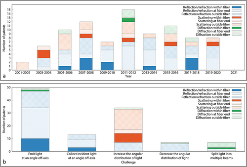
As previously stated, light beam control in medical devices can be used to meet one of five challenges:
emit light at an angle off-axis;
collect incident light at an angle off-axis;
increase the angular distribution of light;
decrease the angular distribution of light;
split light into multiple beams.
An overview of the challenges that can be met with different distal end designs is given in .
Emitting light at an angle off-axis is a challenge that has been thoroughly investigated. All designs include an optical element that induces refraction/reflection or diffraction to direct the light. However, an interface to reflect or refract (96%) light in a specific direction is prevalent compared to a diffraction grating (4%). Using diffraction to emit light at an angle off-axis is a more complex method that could only be useful if the emitted light must have specified features, such as a specific pattern or wavelength. Among the devices that use refraction/reflection, there is no clear preference for one design strategy to emit light at an angle off-axis, as the best strategy depends heavily on the function and the target area of the fiber-optic device. A trade-off must be found between the device’s complexity and a number of desirable features, including compactness, light intensity, longevity, reduced overheating, and patient safety [Citation32].
Light collection at an angle to the device’s longitudinal axis is a challenge with little diversity in the developed designs: all collecting devices included in this review were developed for tissue spectroscopy and make use of refraction or reflection. As refraction/reflection can equally direct a light beam consisting of different wavelengths from a specific tissue region into an optical fiber with a small cross-section, it is a convenient approach for the collection of spectral information off-axis. Patents exist for all of the design strategies. However, none of the patents using the reflective surface inside the optical fiber, such as bent and twisted fibers, are active anymore. This indicates that the design may not have given the desired results, since the respective patents were not extended.
Emitting light with a wide angular distribution is a design challenge that has been thoroughly investigated. The use of a scattering element (76%) is clearly preferred over diverging lenses or coatings (21%) and diffraction gratings (3%). This is because the two latter only increase the angular distribution of a light beam propagating in one specific direction, whereas scattering elements offer the possibility of uniform light distribution over 360°, as required by various applications such as light-induced therapy or illumination [Citation11,Citation95,Citation96]. Among scattering devices, the number of results within each design category demonstrates a clear preference for using a diffuser tip outside the optical fiber to scatter the light. This design strategy has the advantage that it does not require complex fabrication, and the use of scattering particles within an external diffuser tip makes it possible to control the scattering effect by varying the size, material or concentration of the particles [Citation97].
In contrast to the findings for increasing the angular distribution, there is little variation in the designs to decrease the angular distribution of light: all seven devices include a converging lens outside the optical fiber. Because light exiting the optical fiber is always slightly divergent due to total internal reflection within the fiber, placing an optical component outside the optical fiber is the only design option to reduce the angular distribution [Citation11]. Variety exists in the choice of the converging lens: it can be refractive (86%) or diffractive (14%). Using diffraction requires a more complex design; however, diffraction lenses have the advantage of being compact and lightweight, and allow to select a desired wavelength of operation.
The last challenge for light beam control is to split the beam into multiple narrow beams, which is accomplished by only seven devices included in this review. These designs can use a diffraction grating (71%) or a faceted surface that induces refraction/reflection (29%). A diffraction grating is most frequently used because it can serve additional purposes, such as separating light of different wavelengths or creating a multi-spot pattern. Because diffraction gratings include microscopic features that make them challenging to fabricate within the optical fiber core or core end surface [Citation98], using an optical element outside the optical fiber is preferred over other design strategies.
8. Conclusion
This review article provides a comprehensive overview and categorization of the patent literature on distal end designs of fiber-optic medical devices that can steer light in the desired direction. The medical section of the Web of Science DII database was reviewed, and a total of 81 patents published during the last 20 years were discussed. The possible distal end designs were categorized based on the working principle and design strategy for light beam control.
The most common way for steering a light beam in the desired direction is by refraction or reflection. This working principle is preferred to emit and collect light at an angle off-axis and to decrease the angular distribution of light. Scattering with an optical element outside the optical fiber is preferred to increase the angular distribution of light, whereas diffraction with an optical element outside the optical fiber is preferred to split light into multiple beams.
This overview of different distal end designs can be used to identify new design challenges. One of the challenges is to implement diffraction gratings within the optical fiber or at the fiber core end surface. Furthermore, this review reveals that there are still several opportunities to design innovative devices that can collect light at an angle off-axis, reduce the angular distribution of light, or split light into multiple beams. The focus of new designs must remain on optimizing light beam control, mechanical robustness, and patient safety.
9. Expert opinion
9.1. Design suitability for medical purposes
The retrieved patents show that remote light delivery is an issue relevant to various applications involving tissue diagnostics and therapeutics. Spectroscopic devices use light to assess tissue type and status based on its optical properties [Citation99]. Physicians apply spectroscopy to recognize diseases [Citation100] and to distinguish tumors from healthy tissue [Citation101]. On the other hand, photodynamic therapy is used to treat cancer by destroying malignant cells with a combination of light energy and a photosensitive drug [Citation102]. Light can also provide treatment for various other medical conditions, such as benign prostatic hyperplasia [Citation103], kidney and bladder stones [Citation104], or incontinence [Citation105]. New designs can support tissue diagnostics and therapeutics in hardly accessible locations of the body by providing light delivery to and collection from tissue off-axis.
In this review, it became apparent that some medical disciplines are especially demanding of light beam control. Prevalent medical disciplines mentioned in the patents are ophthalmology [Citation13,Citation16,Citation19,Citation23,Citation24,Citation41,Citation48,Citation59–64,Citation67,Citation68,Citation70,Citation79,Citation83,Citation91,Citation93], cardiovascular surgery [Citation15,Citation39,Citation40,Citation42,Citation43,Citation46,Citation52,Citation55,Citation65,Citation80,Citation84], and dentistry [Citation21,Citation22,Citation74,Citation75].
Ophthalmology is a discipline in which optimal illumination is crucial to guarantee surgical safety and effectiveness [Citation106]. Therefore, light diffusion has found its way into surgical practice in the last decennia. New designs contribute to the growing diversity of surgical illumination options. A second widespread ophthalmologic application is laser photocoagulation, a surgery frequently carried out to prevent vision loss in patients affected by diabetes [Citation107], retinopathy of prematurity [Citation108], and other ocular indications. Nagpal et al. [Citation109] have shown that multi-spot photocoagulation leads to faster, less painful procedures with less collateral damage than standard laser treatment, while achieving similar retinopathy regression in diabetic patients. New designs to create multi-spot patterns therefore show great potential for application in laser photocoagulation.
In cardiovascular surgery, light is employed for vessel ablation, blood embolization and tissue welding. Laser procedures for the ablation and reparation of blood vessels have been carried out since the 1970s [Citation110,Citation111]. New designs help to create more versatile tools for this standard surgical procedure.
Dental applications of light beam steering include the treatment of plaque (bacterial microfilms) and tartar (calcified deposits) on teeth and gums by photodisinfection. Photodisinfection employs light of specific wavelengths to eradicate a broad variety of oral microorganisms to prevent or treat oral diseases without inducing resistance [Citation112]. New designs provide better elimination of pathogens by monitoring dosimetry and direction of the administered light.
In all of the abovementioned applications, light is already being employed for illumination, spectral tissue sensing, or cell modification, which shows the validity of the applications proposed in the patents. Better light beam steering can improve these procedures and make the innovative devices usable in areas inaccessible with conventional fiber-optic probes.
9.2. Further research
This review focuses on the distal end of fiber-optic devices that steer light toward the tissue or collect light after interacting with tissue. The search was restricted to devices with direct light tissue interaction for illumination, spectral tissue sensing, laser surgery, or light-induced therapy. Therefore, this research does not include other fiber-optic devices such as imaging devices and temperature, pressure and shape sensors, even though these devices also exert a high level of light control. Especially diffraction is used in many imaging devices to produce multi-spot patterns on tissue. Including imaging devices could thus provide a more detailed overview of all possible distal end designs. Furthermore, because fiber-optic devices are not only used in the medical field, the results of other fields could also lead to a more extensive overview with new creative ideas for steering light in the desired direction.
This review was based on the patent literature published in the last 20 years to provide an overview of the latest distal end designs to steer a light beam. As patents do not present any performance results, additional exploration of the corresponding scientific literature will provide more insights in the technical feasibility for choosing the optimal design for a particular application, and might even reveal certain designs that have not been patented by their inventors.
Furthermore, many applications impose additional requirements on the device, such as certain mechanical properties, prevention of overheating, removal of debris, and patient safety. These are crucial factors to take into consideration in future developments of fiber-optic medical devices.
9.3. Five-year view
The temporal distribution of distal end designs shows that light beam steering has become more popular throughout the 2000s, with a peak in the development of new devices in 2011–2012 when fifteen new patents were issued within two years. Since then, the number of new inventions has remained on a stable level of around ten new patents/two years, indicating that this field is more consolidated now, but still very active with new designs emerging all the time.
The distribution of patents included in this review over the different categories reveals a gap in the development of devices that use diffraction inside the optical fiber or at the fiber core end surface to steer a light beam. This indicates that these two design strategies still have innovative potential in the development of fiber-optic devices for illumination, spectral tissue sensing, or cell modification. For example, a slanted core end surface including a diffractive grating could direct light of a specific wavelength off the fiber axis with the desired illumination profile or multi-spot pattern, while directing light of another wavelength in axial direction.
The number of different designs for steering light, as well as the number of designs disclosed in active patents show that there are only few devices that can collect light at an angle off-axis, reduce the angular distribution of light, or split light into multiple beams. This implies that numerous new developments are possible to address these design challenges. For example, only five designs described in active patents can collect incident light under an angle [Citation33,Citation34,Citation36,Citation56]. Of these designs, only the devices described in three patents [Citation34,Citation36,Citation56] can collect incident light perpendicular to the fiber’s longitudinal axis. Because these patents only describe collecting fibers that are integrated into biopsy devices or catheters, a design for light collection off-axis can still be developed for a wide range of applications.
Finally, next to the conventional optical fibers treated in this review, there is an ongoing development of special fibers, which has led to inventions such as microstructured optical fibers [Citation113,Citation114], polarization maintaining fibers [Citation115], and low-loss optical fibers [Citation116]. When such trends are picked up by the medical industry, the combination of the light beam steering principles explored in this review with special fibers will result in a great range of new medical devices.
Declaration of Interest
BHW Hendriks is an employee of Philips Research. The authors have no other relevant affiliations or financial involvement with any organization or entity with a financial interest in or financial conflict with the subject matter or materials discussed in the manuscript apart from those disclosed.
Article Highlights
•Remote light delivery is an issue relevant to various applications involving tissue diagnostics and therapeutics.
•The four working principles for steering a light beam in the desired direction are refraction, reflection, scattering, and diffraction.
•In fiber-optic medical devices, light can be steered by modifying the total internal reflection pattern inside the optical fiber, by modifying the optical fiber core end surface, or by adding an optical element outside the optical fiber.
•The preferred working principles to emit and collect light at an angle off-axis are refraction and reflection.
•The preferred working principle to increase the angular distribution of light is scattering; the preferred working principle to decrease the angular distribution of light is refraction.
•The preferred working principle to split light into multiple beams is diffraction.
•There are still several opportunities to design innovative devices that can collect light at an angle off-axis, reduce the angular distribution of light, or split light into multiple beams.
Reviewer Disclosures
Peer reviewers on this manuscript have no relevant financial or other relationships to disclose.
Additional information
Funding
References
- Méndez A. Optics in Medicine. In Optics in Our Time. Cham: Springer. 2016. pp. 299-333.
- Floris I, Adam JM, Calderón PA, et al. Fiber optic shape sensors: a comprehensive review. Opt Lasers Eng. 2021;139:106508.
- Roriz P, Silva S, Frazão O, et al. Optical fiber temperature sensors and their biomedical applications. Sensors. 2020;20(7):2113.
- Poeggel S, Tosi D, Duraibabu D, et al. Optical fibre pressure sensors in medical applications. Sensors. 2015;15(7):17115–17148.
- Correia R, et al. Biomedical application of optical fibre sensors. J Opt. 2018;20(7):073003.
- Schena E, Tosi D, Saccomandi P, et al. Fiber optic sensors for temperature monitoring during thermal treatments: an overview. Sensors. 2016;16(7):1144.
- Amanzadeh M, Aminossadati SM, Kizil MS, et al. Recent developments in fibre optic shape sensing. Measurement. 2018;128:119–137.
- Jelínek, F, et al. Minimally invasive surgical instruments with an accessory channel capable of integrating fibre-optic cable for optical biopsy: a review of the state of the art. proceedings of the institution of mechanical engineers, part H. J Eng Med. 2014;228(8):843.
- Keiser Gerd G, et al. Review of diverse optical fibers used in biomedical research and clinical practice. J Biomed Opt. 2014;19(8):080902.
- Yu X, et al. Micro-and nano-fiber probes for optical sensing, imaging, and stimulation in biomedical applications. Photonics Res. 2020;8(11):1703.
- Utzinger Urs U, et al. Fiber optic probes for biomedical optical spectroscopy. J Biomed Opt. 2003;8(1):121.
- Tipler PA, Mosca G. Physics for scientists and engineers. Macmillan; 2007.
- Auld Jack R, Martin M, Papac MJ, et al. inventors; Auld Jack R Martin Michael M Papac Michael J Smith Ronald T Yadlowsky Michael J Alcon Res Ltd, assignee. Ophthalmic endoilluminators with directed light. US patent US 9066678 B2. 2015
- Hanley Brian M, Hixon J, Oskin Christopher L, et al. inventors; Hanley Brian M Hixon Jessica Oskin Christopher L Sinofsky Edward Boston Scient Scimed Inc, assignee. Side-firing laser fiber with internal bent fiber and related methods. US patent US 8657812B2. 2014 2009 Feb 12
- Munger Gareth T, inventor; assignee. Magnetically enabled optical ablation device. US patent US 2007/0049909A1. 2007 2006 Aug 23
- Kern T, Mirsepassi A, Papac Michael J, et al. inventors; Novartis Ag, assignee. Vitreous cutter with integrated illumination system. US patent US 10307290B2. 2019 2016 Jul 06
- Bernardus Hendrikus W H, Kuiper S, De Boer Ruthwilhelmine I, et al. inventors; Koninkl Philips Electronics Nv, assignee. Obtaining optical tissue properties. US patent US 2009/0326385A1. 2009 2007 Nov 29
- Mansour Hebah N, Shehada Ramez Emile N, inventors; Mansour Hebah Noshy Shehada Ramez Emile Necolar, assignee. Methods and sensors for monitoring internal tissue conditions US patent US 7930015B2. 2011 2006 Feb 14.
- Diao C, Farley Mark H, Mirsepassi A, et al.inventors;Alcon Inc,assignee. Multi-fiber multi-spot laser probe with articulating beam separation. US patent US 2020/0390603A1. 2020 2020 Aug 26.
- Cottrell William J, Foster T, inventors; Cottrell William J Foster Thomas, assignee. Side-firing linear fiber optic array for interstitial optical therapy and monitoring using compact helical geometry. US patent US 2009/0221921A1. 2009 2007 Apr 09.
- Bollinger James E, West John D, Ruddle Clifford J, inventors; Bollinger James Edwin West John David Ruddle Clifford J, assignee. Method And Apparatus For Disinfecting Or Sterilizing A Root Canal System Using Lasers Targeting Water. WO patent WO 2009/064947 A1. 2009 2008 Nov 14.
- Bruder G, Kuttler S, Kishen A, inventors; Syact Llp, assignee. Synergistic ultrasonic, sonic or electric energy and light transmitting probe for disinfection of root canals during an endodontic procedure. US patent US 11090135 B2. 2021 2017 Apr 05.
- Grieshaber Hans R, inventor; Grieshaber Hans R Grieshaber Ophtalmic Res Foundation, assignee. Method and device for the pathology analysis of the Schlemm’s canal. US patent US 8747299 B2. 2014 2011 Jun 02.
- Yadlowsky MJ, Papac Michael J, Lassalas B, inventors; Alcon Res Ltd, assignee. Illuminated microsurgical instrument including optical fiber with beveled end face. US patent US 9561085 B2. 2017 2014 Nov 26.
- Harschack A, Neuberger W, inventors; Ceramoptec Ind Inc, assignee. High Durability Side Fire Optical Fiber for High Power Applications. US patent US 2011/0166562 A1. 2011 2010 Jan 04.
- Williamson Steven L, inventor; Picometrix Inc, assignee. Focusing fiber optic. US patent US 7039275 B2. 2006 2002 Nov 15.
- Fairneny TY, inventor; Fairneny Ty Boston Scient Scimed Inc, assignee. Side Fire Laser Assembly With Diffractive Portion US patent US 2011/0299557 A1. 2011
- Hasenberg Thomas C, Xuan Rongwei J, Watschke Brian P, et al. inventors; Boston Scient Scimed Inc, assignee. Surgical laser system and laser fiber. US patent US 10426547 B2. 2019
- Loeb Marvin P, inventor; Trimedyne Inc, assignee. Novel devices for effective and uniform shrinkage of tissues and their unique methods of use. US patent US 2014/0088571 A1. 2014
- Yeik Glenn D, Hernandez Cristobal R, inventors; Trimedyne Inc, assignee. Side firing optical fiber device for consistent, rapid vaporization of tissue and extended longevity. US patent US 2014/0107630 A1. 2014
- Hixon J, Oskin Christopher L, inventors; Hixon Jessica Oskin Christopher L, assignee. Laser fiber capillary apparatus and method. US patent US 2009/0326525 A1. 2009
- Pinnow Douglas A, inventor; Pinnow Douglas Arthur, assignee. Apparatus and methods for side-fire optical fiber assembly suitable for medical applications. US patent US 10603109 B2. 2020
- Huang Z, Bergholt Mads S, Zheng WEI, et al. inventors; Univ Singapore, assignee. Diagnostic instrument and methods relating to Raman spectroscopy. US patent US 2015/0216417 A1. 2015
- Reich C, Hendriks Bernardus Hendrikus W, Bierhoff Waltherus Cornelis J, et al., inventors; Koninklijke Philips Nv, assignee. Side-looking lung biopsy device. US patent US 10405838 B2. 2019
- Ramanujam N, Zhu C, Lubawy C, inventors; Ramanujam Nirmala Zhu Changfang Lubawy Carmalyn, assignee. Side-firing probe for performing optical spectroscopy during core needle biopsy. US patent US 2005/0203419 A1. 2005
- Braun Augustinus L, Hendriks Bernardus HW., Van der vleuten cornelius ANM, inventors; Koninkl Philips Nv, assignee. Biopsy device. EP patent EP 2265161 B1. 2016
- Zuluaga Andres F, Korn Jeffrey A, et al. inventors; Infraredx Inc, assignee. Side firing fiber optic array probe. US patent US 2005/0165315 A1. 2005.
- Rizoiu Ioana M, Jones Jeffrey W, Boutoussov D, inventors; Biolase Inc, assignee. Modified-output fiber optic tips EP patent EP 1711849 B1. 2013.
- Griffin Stephen E, Watson Stuart F, et al. inventors; Innovaquartz Llc assignee. Radial emissions from optical fibers. US patent US 10092356 B2. 2018.• Provides extensive overview of design possibilities to create radial light emission.
- Seymen Ali A, Ortac B, Ozgur E, inventors;E A Teknoloji Biyomedical Cihazlar Dijital Ve Optik Sistemler Nanoteknoloji Ar Ge Ith Ihr Taah Sanvamet Medikal Saglik Urunleri Ve Hizmetleri Karyakit Enerji Madencilik Gida Elektronik Sanayi Ve Tic, assignee. Fiber probe that emits a pair of ring beams for laser ablation. US patent US 2020/0237439 A1. 2020.
- Scheller Gregg D, Easley James C, inventors; Synergetics Inc, assignee. multiple target laser probe. US patent US 2008/0051770 A1. 2008.
- Neuberger W, inventor;Neuberger Wolfgang Biolitec Unternehmensbeteiligungs Ii Ag, assignee endoluminal laser ablation device and method for treating veins. US patent US 9693826 B2. 2017.
- Tang J, et al. inventor; Cornova Inc, assignee Shaped fiber ends and methods of making same. US patent US 2009/0227993 A1. 2009.
- Rabiner Robert A, Colleran Dennis P, Anthony W O, et al. inventors; Rabiner Robert A Colleran Dennis P O’leary Anthony W Dye Justin Gdrew Mark A Illuminoss Medical Inc, assignee. Systems and methods for internal bone fixation. US patent US 8906030 B2. 2014
- Bissig A, Zurfluh E, Rose A, inventors; Bissig Alois Zurfluh Erich Rose Andreas, assignee. Light delivery device. US patent US 9067059 B2. 2015 2009/02/12. ROSE ANDREAS, assignee. Light delivery device. US patent US 9067059 B2. 2015.
- Wu X, Luo Z, Xie D, et al. inventors; Covidien Lp, assignee Fiber optic laser surgical instrument having a radial dispersion pattern. US patent US 10543042 B2. 2020.
- Shang HUA, inventor SHANG, assignee HUA. Photodynamic therapy diagnostic device capable of optical fiber puncture. US patent US 10463876 B1. 2019
- Auld Michael D, inventor; Synergetics Inc Auld Michael D, assignee Optic fiber instrument with microsphere diffraction surface WO patent WO 2006/084124 A2. 2006.
- Hanley B, Hixon J, Oskin Christopher L, et al. inventors; Boston Scient Scimed Inc, assignee Side-firing laser fiber with protective tip and related methodS US patent US 2018/0214211 A1. 2018.
- Yu H, Xuan Rongwei J, Zhang Jian J, inventors; Boston Scient Scimed Inc, assignee. Side-fire laser fiber having a molded reflective surface. EP patent EP 3270810 B1. 2019.
- Sudarshanam Venkatapuram S, inventor; Ams Res Corp Sudarshanam Venkatapuram S, assignee. Side-firing optic fiber tip with length-based beam diameter. WO patent WO 2010/075368 A1. 2010.
- Frenz M, Ott B, inventors; Storz Endoskop Gmbh, assignee. Apparatus for applying light to a vessel wall. US patent US 7108692 B2. 2006.
- Brown Joe D, Malphurs D, inventors; Brown Joe D Malphurs Daniel, assignee. Interchangeable forward or sidefiring tip with stand off catheter. US patent US 2019/0018195 A1. 2019
- Furnish Simon M, inventor; Prescient Medical Inc Furnish Simon M, assignee. Miniature fiber optic spectroscopy probes. WO patent WO 2007/146254 A2. 2007
- Fulghum S, inventor; Newton Lab Inc, assignee. Optical probe for Raman scattering from arterial tissue. US patent US 2007/0038123 A1. 2007.
- Furnish Simon M, inventor; Infraredx Inc Furnish Simon M, assignee. Catheter probe arrangement for tissue analysis by radiant energy delivery and radiant energy collection. US patent US 8386023 B2. 2013.
- Jono J, Takimura T, Tao S, inventors; Jono Junichi Takimura Toshinori Tao Shoichikonica Minolta Inc, assignee. Probe. US patent US 8942523 B2. 2015.
- Li J, inventor; Li Jamie Boston Scient Scimed Inc, assignee. Laser assembly having adjustable focusing lenses. US patent US 9987090 B2. 2018.
- Diao C, Farley Mark H, Mirsepassi A, et al.inventors; Alcon Inc, assignee. multi-fiber multi-spot laser probe with simplified tip construction US patent US 2020/0397614 A1. 2020.
- Smith Ronald T, inventor; Novartis Ag, assignee. BSS-only multi-sport laser probe. US patent US 10111778 B2. 2018.
- Maholtra M, inventor; H S Int Corp, assignee. wide angle illumination system and method. US patent US 2017/0333151A1 . 2017.
- Smith Ronald T, inventor; Smith Ronald T, assignee. Beveled tip surgical wide-angle illuminator. US patent US 2009/0161384 A1. 2009.
- Hickingbotham D, inventor; Alcon Inc, assignee. Surgical wide angle illuminator. EP patent EP 1522290 B1. 2006.
- Charles Steven T, inventor; Alcon Inc, assignee. Gradient index surgical illuminator. US patent US 7824089 B2. 2010.
- Rune TP, inventor; Cook Medical Technologies Llc, assignee. Optical energy delivery and sensing apparatus. GB patent GB 2562526 B. 2019.
- Nagale S, Larson Michael C, Boden M, inventors; Boston Scient Scimed Inc, assignee. Methods and devices for targeted ablation of tissue. US patent US 10695128B2. 2020.
- Mirsepassi A, Smith Ronald T, Papac Michael J, et al. inventors; Novartis Agalcon Inc, assignee. Diverging light from fiber optics illumination delivery system. US patent US 10859748 B2. 2020.
- Peterson Erik W, inventor; Medical Instr Development Laboratories Inc, assignee. Application of highly scattering materials to surgical illumination. US patent US 10441156 B2. 2019.
- Neuberger W, Spaniol S, inventors; Ceramoptec Ind Inc Neuberger Wolfgang Spaniol Stefan, assignee. medical light diffusers for high power applications and their manufacture. WO patent WO 2008/024397 A2. 2008
- Luloh KP, Annen M, Tornambe P, et al. inventors; Luloh K. Peter Annen Michael Tornambe Paul Koch Frank H.J., assignee. Apparatus and method for illuminating a field of view within an eye. US patent US 2003/0169603 A1. 2003.
- Skutnik Bolesh J, inventor; Ceram Optec Ind Inc, assignee. Device and method to scatter optical fiber output. US patent US 6810184 B2. 2004.
- Mersch Steven H, inventor; Indigo Med Inc, assignee. Durable fiber optic diffuser tip and method of making same. US patent US 6576163 B2. 2003.
- Sinofsky Edward L, inventor; Sinofsky Edward L, assignee. system and method for optical fiber diffusion. WO patent WO 2010/051463 A2 2010.
- Williams Jill ANN, Clements David J, Pearson Gavin J, et al. inventors; Denfotex Ltd, assignee. Method and apparatus for filling a dental root canal. US patent US 7306459 B1. 2007.
- Hamada K, inventor; Hamada Kazunori Morita Mfg, assignee. Dental laser radiation chip. US patent US 8224138 B2. 2012.
- Loebel N, inventor; Ondine Int Ltd, assignee. fiber optic probe for use in a medical device and method of making it EP patent EP 1778118 B1 . 2013.
- Levin P, Kazlas P, Sinofsky Edward L, et al. inventors; Lumerx Inc Levin Philip Kazlas Peter Sinofsky Edward L Evans Stephen P Guiles Marvin Goncalves David P Tolkoff Marc J Cerier Jeffrey C Abraham Richard, assignee light-wand and balloon catheters. WO patent WO 2008/066943 A2. 2008.
- Maitland Duncan J, Iv W S, Wilson Thomas S, et al. inventors; L Livermore Nat Security Llc, assignee. System for diffusing light from an optical fiber or light guide. US patent US 7386203 B2. 2008.
- Nappi Richard B, Overaker Ronald F, Toth Cynthia A, et al. inventors; Univ Duke Nappi Richard B Overaker Ronald F Toth Cynthia A Dodge Brian C Nguyen Hoang Winter Katrina P, assignee. optical fiber illuminators having integral distal light diffusers especially useful for ophthalmic surgical procedures, and methods of making the same. WO patent WO 2005/052643 A2. 2005
- Bays R, Mosimann L, Woodtli A, et al. inventors; Pharmacyclics Inc Bays Roland Mosimann Laurent Woodtli Alain Cheong Wai-Fung, assignee light delivery device using conical diffusing system and method of forming same. WO patent WO 2003/065880 A2. 2003
- Gowda A, McNichols Roger J, Gelnett M, et al. inventors; Biotex Inc, assignee. Light diffusing tip. US patent US 7412141 B2. 2008.
- Intintoli Alfred J, Franz D, inventors; Surgical Laser Tech, assignee. Light-dispersive probe. US patent US 6893432 B2. 2005 2002/03/22.Cheong Wai-Fung, assignee. light delivery device using conical diffusing system and method of forming same. WO patent WO 2003/065880A2. 2003
- Smith Ronald T, inventor;Smith Ronald T Novartis Ag,assignee.Surgical variable-angle illuminator. US patent US 8152798 B2. 2012.
- Ward JIM, Williams Mathew R, inventors; Edwards Lifesciences Corp, assignee. Ablative treatment of atrial fibrillation via the coronary sinus. US patent US 7731715B2 . 2010 2004 Dec 10
- Furuta K, inventor; Olympus Corp, assignee. Illumination device. US patent US 9753270 B2. 2017.
- Yoshida K, Kasamatsu T, Yoshihiro T, inventors yoshida koji kasamatsu tadashi yoshihiro tatsuya fujifilm corp light diffusing element and light assignee.guide for endoscopes equipped with the light diffusing element. US patent US 8849079 B2. 2014.
- Henriksson Paer H, inventor; Henriksson Paer Hclinical Laserthermia Systems AB, assignee. A system for providing insertable probes. WO patent WO 2011/161126 A1. 2011.
- Kikuchi S, Kobayashi H, inventors; Olympus Corp, assignee. Illumination optical system for endscope and endoscope. US patent US 2014/0357948 A1. 2014.
- Moor Robert N, Jean Justin K, Lohrenz R,inventors; Lasertel Inc, assignee. Source-insensitive cylindrical light diffuser and visual indicator system for phototherapy. US patent US 2017/0340898 A1. 2017.
- Zerfas Jeffrey W, inventor; Zerfas Jeffrey W Boston Scient Scimed Inc, assignee. Methods and apparatus related to a side-fire assembly that has an optical grating. US patent US 8870858 B2. 2014.
- Murakami N, Ito K, inventors; Murakami Naho Ito Koichi Nidek Kk, assignee. Ophthalmic laser treatment apparatus. US patent US 9023017 B2. 2015.
- Kirkegaard Henriette S, Hansen A, Hansen Steen M, inventors; 3dintegrated Aps, assignee. A medical probe assembly. WO patent WO 2018/113887 A2. 2018.
- Ronald T, inventor; Smith Ronald T Alcon Res Ltd, assignee. Multi-spot laser probe US patent US 8951244 B2. 2015.
- Yelin D, Bouma BE, Rosowsky JJ, et al. Doppler imaging using spectrally-encoded endoscopy. Opt Express. 2008;16(19):14836.
- Algorri JF, Ochoa M, Roldán-Varona P, et al. Light technology for efficient and effective photodynamic therapy: a critical review. Cancers (Basel). 2021;13(14):3484.
- Soukos NS, Chen PSY, Morris JT, et al. Photodynamic therapy for endodontic disinfection. J Endod. 2006;32(10):979.
- Li M, Vu T, Sankin G, et al. Internal-illumination photoacoustic tomography enhanced by a graded-scattering fiber diffuser. IEEE Trans Med Imaging. 2021;40(1):346–356.
- Hill KO, Meltz G, et al. Fiber bragg grating technology fundamentals and overview. J Lightwave Technol. 1997;15(8):1263–1276.
- Jacques SL, et al. Optical properties of biological tissues: a review. Phys Med Biol. 2013;58(11):R37.
- Richards-Kortum R, Sevick-Muraca E, et al. Quantitative optical spectroscopy for tissue diagnosis. Annu Rev Phys Chem. 1996;47(1):555–606.
- Evers D, Hendriks B, Lucassen G, et al. Optical spectroscopy: current advances and future applications in cancer diagnostics and therapy. Future Oncol. 2012;8(3):307–320.
- Dolmans DE, Fukumura D. Jain RK, et al. Photodynamic therapy for cancer. Nat Rev Cancer. 2003;3(5):380–387.
- Kuntz RM, et al. Laser treatment of benign prostatic hyperplasia. World J Urol. 2007;25(3):241–247.
- Rodríguez D, Sacco DE, et al. Minimally invasive surgical treatment for kidney stone disease. Adv Chronic Kidney Dis. 2015;22(4):266–272.
- Ogrinc UB, Senčar S, Lenasi H, et al. Novel minimally invasive laser treatment of urinary incontinence in women. Lasers Surg Med. 2015;47(9):689–697.
- McCannel C. Illumination considerations for vitreous surgery. In: Saxena S, Meyer CH, Ohji M, et al., editors. Vitreoretinal Surgery. London: Jaypee Brothers Medical Publishers; 2012. pp. 8–14.
- Group DRSR, et al. Preliminary report on effects of photocoagulation therapy. Am J Ophthalmol. 1976;81(4):383–396.
- Iverson DA, Trese MT, Orgel IK, et al. Laser photocoagulation for threshold retinopathy of prematurity. Arch Ophtalmol. 1991;109(10):1342–1343.
- Nagpal M, Marlecha S, Nagpal K, et al. Comparison of laser photocoagulation for diabetic retinopathy using 532-nm standard laser versus multispot pattern scan laser. Retina. 2010;30(3):452.
- Bass LS, Treat MR, et al. Laser tissue welding: a comprehensive review of current and future. Lasers Surg Med. 1995;17(4):315.
- Esenaliev RO, Oraevsky AA, Letokhov VS, et al. Laser ablation of atherosclerotic blood vessel tissue under various irradiation conditions. IEEE Trans Biomed Eng. 1989;36(12):1188–1194.
- Wilson M, et al. Photolysis of oral bacteria and its potential use in the treatment of caries and periodontal disease. J Appl Bacteriol. 1993;75(4):299–306.
- Eggleton BJ, Kerbage C, Westbrook P, et al. Microstructured optical fiber devices. Opt Express. 2001;9(13):698–713.
- Russell PSJ, et al. Photonic-crystal fibers. J Lightwave Technol. 2006;24(12):4729–4749.
- Noda J, Okamoto K, Sasaki Y, et al. Polarization-maintaining fibers and their applications. J Lightwave Technol. 1986;4(8):1071–1089.
- Kapron F, Keck DB, Maurer RD, et al. Radiation losses in glass optical waveguides. Appl Phys Lett. 1970;17(10):423–425.