
 ?Mathematical formulae have been encoded as MathML and are displayed in this HTML version using MathJax in order to improve their display. Uncheck the box to turn MathJax off. This feature requires Javascript. Click on a formula to zoom.
ABSTRACT
For the continuous development of ultra high temperature ceramic matrix composites manufactured using reactive melt infiltration (RMI), the influence of three different melt alloys and two preform routes on mechanical behaviour and melt infiltration is investigated. Contact angle and viscosity measurement are performed to describe the melt infiltration process. The purpose of these experiments is to further understand the RMI process and increase the mechanical performance of the material. The infiltration height of molten metals within capillary systems depends on the measured contact angles and viscosity as well as the different phases present in the preform, matrix and fibre coating. In order to successfully maintain mechanical performance, minimal reactivity between the melt and coating/fibres is desired. Resulting phase formations, for each manufacturing step, are investigated and analysed using SEM, EDX and XRD. Mechanical performance is determined using flexural strength by three-point-bending, achieving close to 400 MPa with fabrics.
1. Introduction
Ultra high temperature ceramics (UHTCs) are a key factor in hypersonic flight and other extreme temperature applications, reaching C and higher. Without using active cooling systems, UHTCs are one of the few materials able to withstand these temperatures and to some degree the occurring oxidation, as discussed in several publications [Citation1–5]. In recent years, the focus of UHTC development has concentrated on including fibre reinforcement to increase their damage tolerance. Methods used to manufacture these ultra high temperature ceramic matrix composites (UHTCMCs) are sintering [Citation6], chemical vapour infiltration [Citation4,Citation7] and reactive melt infiltration (RMI) [Citation8,Citation9]. The Focus of this study will be the investigation of melt and preform–matrix interactions occurring during the RMI process, several of which occur at the same time. Phases which do interact are alloy elements (Zr/Cu/Ag/B) and matrix or fibre-coating elements (ZrB
/TiB
/B
C/B/C). The matrix interaction can be separated into interaction prior to and after the chemical reaction. The results are used to neutralise low melting phases by dissolution and formation of more refractory compounds. The advantages and disadvantages of the Zr RMI are comparable to the liquid silicon infiltration (LSI) process, namely low porosity, residual melt and manufacturing of large parts. In case of fibre-reinforced ZrB
matrix composite, RMI allows a lower temperature exposure of the fibres compared to HP or SPS, with no additional mechanical pressure. However fibres need to withstand the melt during the RMI process. The purpose of these experiments is to further understand the RMI process and determine the necessary thickness of fibre coatings. The infiltration height of molten metals within capillary systems is highly dependent on their contact angles, and as such, it is important that the chosen element combinations do promote wetting behaviour. In order to successfully maintain mechanical performance, minimal reactions between the melt and coating are desired. This allows for adequate degradation protection without the need for thick coating layers. Melts investigated are Zr
Cu and Zr
Ag, including 1 at.-% B additions. Zr
B is only used for mechanical characterisation, due to its high melting point. A sample using each of these melts is manufactured in combination with a polycarbosilane and phenolic-based preform.
2. Experimental methods
Each process state is analysed and compared via SEM, Zeiss Ultra 55 Plus with Angular selective Backscattered detector (AsB), and EDX from Oxford using a detector size of . Porosity of pyrolysed preforms is determined by mercury porosimetry, CE Instruments Pascal 240. XRD analysis is performed using a Bruker AXS D8 with Cu Kα (λ
pm). Contact angles are measured using the DSAHT17 system from KRÜSS, up to
C and Ar atmosphere. A peak temperature of
C is set, to be reached via radiative heating. Heating rates are set as follows: 10 K min−1 from 25 to 1000
C, 7 K min−1 from 1000 to 1200
C and 5 K min−1 between 1200 and 1550
C. The influence of differing heating rates is determined during preliminary testing to be minimal, with a variation of less than
at any given time across 1000–1500
C (when comparing the chosen heating rate against half-speed). The peak temperature for each experiment, between 1500 and 1550
C, is held for 20 min before cooling begins at a rate of 5 K min−1. The DSA4 camera system takes drop-shape images of the melts shadow and records the associated contact angle; taking 4–5 images K−1. The DSA4 software measures the volume and surface area of the drop as it wets, fitting the silhouette toYoung–Laplace or Tangent algorithms and providing information about the melts spreading behaviour. Viscosity of melts are measured by Anton Paar Germany GmbH using a FRS 1800 DSR 502 system. Different shear rates and temperatures, upon melting to
C or maximum torque, using three different melt alloys are measured. Starting at slightly above melting temperature, the viscosity is measured with a constant shear rate of 15, 25, 50 and 70 s−1, followed by a shear rate ramp from 1 to 75 s−1. Heating ramps are performed under a constant shear rate of 25 s−1. To determine the mechanical behaviour, three-point bending (3PB) tests are performed at room temperatures. The tests are performed according to standard DIN EN 658-3 [Citation10]. The tests are performed with a universal testing machine from Zwick GmbH & Co. KG. Each composition is tested using three samples; the average and standard deviation, considering a normal distribution, is calculated. The ratio of bearing distance and sample thickness is kept at a ratio grater than 20. The upper loading bearing has a radius of 5 mm and the two lower bearing have a radius of 2 mm. The testing speed of each sample was 1 mm min−1.
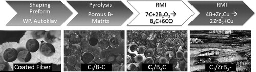
3. Manufacturing
Similar to LSI, a ZrB formation with Zr-based melts requires attention of the following aspects. A Boron containing porous preform with a capillary system is necessary, which enables liquid melt infiltration. As there are no precursors yet to build boron chains, it is necessary to produce a powder-based slurry which can be infiltrated into fibre bundles. Additionally, the composition of the Zr-based melts needs to be taken into account. Different alloy compositions do influence contact angles, viscosity, phases forming and melting temperature. The three-step process, as described in the previous work [Citation8,Citation9], for UHTCMCs manufactured by RMI is shown in . Compared to the previous work, an additional B
O
infiltration of phenolic-based preforms is introduced. This additional step enables the infiltration with Zr alloys without polycarbosilanes.
Figure 1. Schematic of the RMI process.
3.1. Slurry infiltration and pyrolysis
Each precursor is mixed with boron powder, Tradium GmbH amorphous Boron powder 95/97, and impregnated onto fabrics through a foulard (Mathis AG), varying in boron content from 20 to 70 wt-%. Two precursors are used – a polycarbosilane, essentially forming a SiC matrix, and a phenolic, essentially forming C during pyrolysis. Boron is mixed with the precursors prior to handling in a foulard. The foulard has two cylinders rotating under a defined pressure contact. The fibre sheets are stacked into a mould and transferred to a warm press orautoclave for curing. The phenolic-based slurry is infiltrated after drying the stacked fabrics using a vacuum bagging infiltration method.
To prevent the zirconium–carbon reaction during Zr infiltration of the carbon fibres, GRANOC XN-80 weaves are coated with a TiB coating by chemical vapour deposition in a standard CVD reactor (built by Surmetal, Switzerland). The reaction of TiCl
(flow rate: 0.2 slm) with BCl
(flow rate: 0.4 slm) and H
(flow rate: 10.0 slm) forms TiB
and HCl at
C. The coating pressure is 300 mbar and the coating time varies between 2 and 4 h, with a growth rate of around
. During the CVD process, each fabric is placed separate inside the reaction chamber.
Both compositions are pyrolysed at C in Ar atmosphere. For both precursors, the main mass loss is before reaching
C. From investigating thermogravimetric analysis (TG) and SEM images after pyrolysis, we find that there is no apparent reaction of the boron powder and precursors during pyrolysis cycles.
3.2. Boron oxide infiltration
A method enabling Zr RMI for a phenolic-based boron slurry needs to increase pore diameters and improve the contact angle within the pore structure. Essentially the phenolic resin could be depleted for adaption of the pore size distribution with an additional internal coating of the pore structure after pyrolysis to adapt the contact angle. The coating itself will again influence the pore size distribution due to the deposition of material. Instead the following reaction can be used to influence both factors at once:(1)
(1) Decrease in volume enlarges the pore size distribution and the contact angle will be enhanced due to B
C formation. B
O
has a melting point of ∼475
C and upon melting will start to infiltrate into the capillary system of the preform. The formation of B
C will start at higher temperatures according to the literature [Citation11–13]. Jung et al. [Citation12] describes the influence of pyrolysis temperature, dwelling time and carbon content on the formation of B
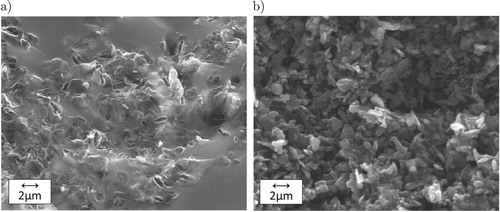
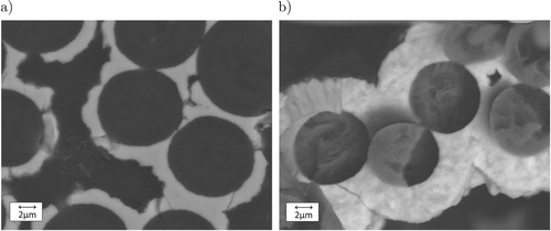
C. shows a SEM image of a phenolic-based pyrolysed composite on the left and the same composition after B
O
infiltration and pyrolysis at
C on the right. Most of the amorphous carbon is being transformed into B
C, leaving a larger pore structure.
Figure 2. Matrix micro-structure before (a) and after BO
infiltration (b).
shows the pore size distribution of the different precursors, polycarbosilane, phenolic resin and phenolic resin after BO
infiltration. Polycarbosilane has a very large bandwidth of larger pores compared to phenolic resin. Pore size distribution of B
O
infiltrated sample are similar in bandwidth and size to polycarbosilane samples and therefore promote infiltration with Zr alloys. Once the carbon is consumed, additional infiltration cycles do not change the pore size distribution further, as shown by the bottom graph of . This is also observed by measuring overall porosity and mass change during pyrolysis. The amount of B
O
can be calculated by the ceramic yield of the phenolic resin and the fibre volume content. Besides contact angles and overall porosity, adopted pore sizes are essential for Zr-based RMI. The formation of ZrB
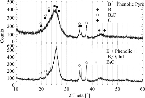
and ZrC do include a volume expansion, when compared with the volume of C or B. If the pore sizes are too small, they are blocked by the volume expansion and infiltration is chocked. shows an XRD analysis of a pyrolysed phenolic slurry-based sample, including carbon fibres, in comparison to an identical sample infiltrated with B
O
. Each sample is pyrolysed at
C and infiltration is taken to
C in order to start B
C formation, both in Ar atmosphere. The XRD shows that both B and B
C signals become more prominent. This is due to the formation of B
C and consumption of the amorphous C, from the phenolic precursor. As described in the SEM images in . TG analysis of pure B
O
powder and carbon from a pyrolysed phenolic with B
O
powder up to
C shows a mass loss of the mixture being slightly lower due to the formation of B
C instead of evaporation of the B
O
. At
C evaporation of the B
O
becomes much more rapid, as seen by rapid increase of mass loss of pure B
O
. In order to promote B
C formation heating rates from
C onward should be at max.
Figure 3. Pore size distribution of pyrolysed polycarbosilane, phenolic resin and phenolic resin after BO
infiltration.
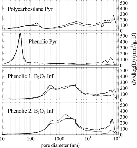
Figure 4. XRD of pyrolysed phenolic samples with and without BO
infiltration.
3.3. Reactive melt infiltration
Melt infiltration is performed as described by Kütemeyer et al. [Citation8,Citation9], heating melt and samples separate from each other in order to control infiltration temperature, ranging from 1500 to 1900C. As shown in the previous work, TiB
is a suitable protection for carbon fibres during the RMI process. Oxidation resistance of TiB
at ultra high temperatures is, however, inferior compared to ZrB
[Citation3,Citation14,Citation15]. Hence the TiB
coating thickness should be as thin as possible. In addition, a thick fibre coating will start to seal the fibre bundles, not allowing any boron slurry or melt to infiltrate into the fibre bundles. shows the TiB
coating thickness after (a) 2 h and (b) 4 h of CVD process time. Due to the linear behaviour of this process, as long as bundles are not sealed and surface areas start to change rapidly, the 4 h process produces twice the coating thickness of around
.
Figure 5. Carbon fibres with TiB coating after (a) 2h and (b) 4h CVD coating time.
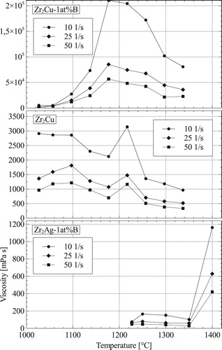
In addition to contact angles, viscosity of the melts influences infiltration. shows the viscosity of ZrCu, Zr
Cu-1 at.-%B and Zr
Ag-1 at.-%B over temperature at shear rates of 10, 25 and 50 s−1. Zr
Cu, being the only one with no B addition, shows an expected decrease in viscosity when temperature is raised. Both alloys containing B do increase rapidly in viscosity within
K upon melting. All of them do decrease in viscosity with increasing shear rates. Upon melting Zr
Cu and Zr
Cu-1 at.-%B are similar in viscosity. In the range of 1000–1100
C, Zr
Cu-1 at.-%B starts increasing in viscosity, while Zr
Cu does become lower in viscosity. Zr
Ag-1 at.-%B decreases in viscosity until
C, showing an increases in viscosity at
C. Experiments have been performed with graphite crucibles, which can cause reactions with the liquid Zr or changing the alloy composition to include C. SEM and EDX analysis show a small ZrC layer on the crucible and rod after testing. Micro-structures of Zr
Cu-1 at.-%B and Zr
Ag-1 at.-%B show scersed ZrB
particles as well as Zr rich phases inside the Zr
Cu/Zr
Ag melt after the tests. Both melts also infiltrate a few mm into the carbon crucible and rod. Measurements from Zr
Cu are more stable when increasing shear rates as compared to Zr
Cu-1 at.-%B, may be due to the formation of ZrB
particles within the melt. Slightly above melting temperature,
C, both alloys do have similar viscosity across the shear rate spectrum. Until
C Zr
Ag-1 at.-%B has the lowest viscosity of the tested melts.
Figure 6. Viscosity in dependence of temperature at three different shear rates for different melts.
Due to comparison, each of the tested samples is infiltrated at C using Zr
Cu-1 at.-%B and Zr
Ag-1 at.-%B alloys, additional infiltrations at
C for a Zr
B alloy are performed. Lower infiltration temperatures are not possible for the polycarbosilane samples due to a large volume expansion described by Kütemeyer et al. [Citation9]. Each sample is heated separate from the melt and upon reaching
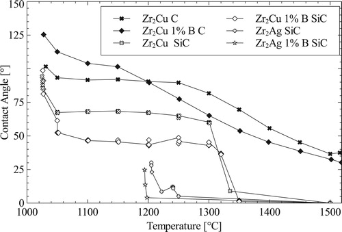
C is lowered into the melt. To further increase capillary force, infiltration are performed in vacuum atmosphere. shows the contact angles of Zr
Cu, Zr
Ag, Zr
Cu-1 at.-%B and Zr
Ag-1 at.-%B melts on C and SiC substrate to determine their performance for RMI. SiC is an important substrate to determine the wetting behaviour of each melt for polycarbosilane sample infiltration. The Ag-based alloys immediately drop in contact angle on SiC after melting, Cu-based alloys keep constant for around
K on SiC before dropping to low contact angles (
). For both substrates and alloy types, B addition lower the contact angles. Zr
Cu and Zr
Cu-1 at.-%B do not drop under
on C substrates, which is why infiltration of samples with high C content only infiltrates a few mm. Contact angles for B
C substrates will be determined while continuing RMI research.
Figure 7. Contact angles of different melt alloys on C and SiC substrates.
From contact angle measurements two different melts are determined to be using as infiltration alloys. ZrB is chosen as an additional candidate for these investigations, even though its contact angle could not be determined due to its high melting point. The advantage of Zr
B is the absence of any low melting phases and large ZrB
grain, which form during RMI. All trials are performed with the same heating rates, dwelling time at peak temperature and infiltration times. The infiltration time is set to 20 min, ensuring a full infiltration of each sample. Each preform manufacturing rout is tested with each of the alloys and evaluated according to its mechanical properties and phases formed within its micro-structure, shown in . In each of the six variations, ZrB
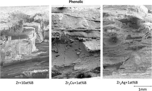
and ZrC are the main phases. The different alloys do influence the residual melt in between the UHTC grains. Both preform manufacturing methods show similar fracture surface on 3PB tests. The main difference in fracture surfaces is between the different melts used for infiltration. While Zr
Cu-1 at.-%B and Zr
Ag-1 at.-%B are similar, the Zr
B infiltrated samples have a different fracture behaviour, as shown exemplary for the phenolic preform in . The different behaviour is due to the incomplete infiltration of the fibre bundles, when using the Zr
B alloy. Either the viscosity of the alloy is not low enough to fully infiltrate the bundles, or the formation of ZrC and ZrB
and their volume expansion is preventing a full infiltration.
Figure 8. Matrix variations within the micro-structure when using different melts and preforms.
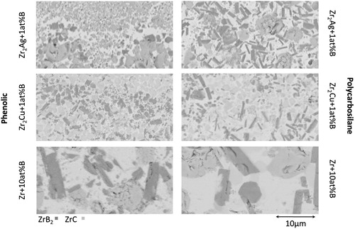
Figure 9. Fracture surface after 3PB of the phenolic preform for each of the three melts.
shows the result of 3PB tests performed for each melt and preform. ZrCu-1 at.-%B reaches the highest bending strength and ultimate strain, with the polycarbosilane-based preform being slightly higher than the phenolic based. All specimens initialised a crack on the bottom side under tensile loading. Every combination does show fibre pull-out and crack deflection. However, these mechanisms are not as distinct as in previous works [Citation9], most likely due to the thinner TiB
fibre coating.
Table 1. Mechanical properties, ultimate stress  , modulus E and ultimate strain , of tested melt and preform combinations.
4. Discussion
Infiltration of BO
does essentially decrease ceramic yield of preforms by mass loss due to CO formation. In terms of RMI for ZrB
a high porosity and low C contents are favourable. Most critical for the B
O
treatment is an eventual fibre degradation. As the Zr melt, the B
O
does infiltrate using the capillary system of the preform, also reaching within the fibre bundles. Due to the TiB
fibre coating, already protecting the fibres from Zr melt, this aspect is not causing any problems upon manufacturing. Evaporation of the B
O
, as shown by TG measurements, does need to be compensated by additional B
O
and fast heating rates above
C. Additional investigations will show, whether B
O
does infiltrate as a liquid into the pore system or as a gas phases upon evaporation. Compared to UHTCMC infiltrated by Kütemeyer et al. [Citation9], carbon fibres in this work have been coated with
TiB
instead of
. Therefore, more fibres are degraded during RMI, forming a matrix dominant behaviour. Highest bending strength is achieved using the Zr
Cu-1 at.-%B melt with very little difference between polycarbosilane and phenolic preform, see . Beside the absence of Cu phases within the Zr
B infiltrated samples, the ZrB
grain forming within these samples are much large by almost a factory of 10. Both larger grains and higher infiltration temperature could influence bending strength. Zr
Ag-1 at.-%B infiltrated samples generate the lowest bending strength. By examining the tested samples, larger crack like pores are found within the matrix of the samples. They appear to be more frequently between each fabric layer. These pores could either be forming due to the lower viscosity of the Ag-based melts, draining the centre of large pore channels. They could also be forming by evaporating Ag having a boiling point of
C, which could be reached by the exothermic reaction, further increasing samples temperature from
C at initialising infiltration. Cu would increase this temperature limit to a boiling point of around
C.
Beside viscosity and different phases forming, the governing influence for RMI are the contact angles forming. While Zr alloys drop in contact angle to about on C substrates, they are not infiltrating preforms containing high C contents. Further research should investigate, whether contact angles of
on C are only reached do to the formation of ZrC. SiC substrates, representing polycarbosilane behaviour, do drop in contact angle at around
C and start to show sufficient infiltration, see , which could also occur do to ZrC formation.
5. Conclusion
As described, a phenolic-based preform in combination with a BO
infiltration enables a Zr alloy-based RMI. Bending strength are almost the same as polycarbosilane-based sample, but manufacturing costs are lower. Zr
Cu-1 at.-%B melts reach 393 MPa 3PB strength compared to 190 MPa of Zr
B at room temperature. Cu phases are low within the Zr
Cu-1 at.-%B samples and can be reduce further, however high temperature strength might be less influenced when using the Zr
B melt. Without having the limitation from volume expansion by the phases forming at temperatures below
C, when using a polycarbosilane-based preform, infiltration temperatures can be further reduced without interrupting RMI. Further investigations will concentrate on the opportunity to manufacture UHTCMC at temperature below
C.
Acknowledgement
This paper was originally presented at the Ultra-High Temperature Ceramics: Materials for Extreme Environments Applications IV Conference (Windsor, UK) and has subsequently been revised and extended before consideration by Advances in Applied Ceramics.
Disclosure statement
No potential conflict of interest was reported by the authors.
ORCID
Stefan Rosiwal http://orcid.org/0000-0002-5728-0635
Additional information
Funding
References
- Glass DE. Physical challenges and limitations confronting the use of UHTCs on hypersonic vehicles. AIAA. 2011.
- Loehman R, Corral EL, Dumm HP, et al. Ultra high temperature ceramics for hypersonic vehicle applications. 2006. (Sandia Report).
- Opeka MM, Talmy IG, Zaykoski JA, et al. Oxidation-based materials selection for 2000°C + hypersonic aerosurfaces. Theoretical considerations and historical experience. J Mater Sci. 2004;9:5887–5904. doi: 10.1023/B:JMSC.0000041686.21788.77
- Paul A, Jayaseelan DD, Lee W. UHTC composites for hypersonic applications. ACS Appl Mater Interface. 2011. 2011.
- Scatteia L, Borrelli R, Marino G, et al. Characterization and process of new metal diboride compound for TPS applications. AIAA/CIRA 13th International Space Planes and Hypersonic Systems and Technology Proceedings American Institute of Aeronautics and Astronautics, Reston, VA. 2005.
- Zoli L, Sciti D. Efficacy of a ZrB2-SiC matrix in protecting C fibres from oxidation in novel UHTCMC materials. Mater Design. 2017;113:207–213. doi: 10.1016/j.matdes.2016.09.104
- Paul A, Rubio V, Binner J, et al. Evaluation of the high temperature performance of hfb2 uhtc particulate filled cf/c composites. Int J Appl Ceram Technol. 2017;14(3):344–353. doi: 10.1111/ijac.12659
- Kütemeyer M, Shandler D, Koch D, et al. Reactive meltinfiltration of boron containing fiber reinforced preforms forming a ZrB2 matrix. In: Mahmoud MM, Bhalla AS, Bansal NP, et al., editors. Ceramic Transactions. Hoboken (NJ): John Wiley & Sons; 2015. p. 464.
- Kütemeyer M, Schomer L, Helmreich T, et al. Fabrication of ultra high temperature ceramic matrix composites using a reactive melt infiltration process. J Eur Ceram Soc. 2016 Nov;36(15):3647–3655. Available from: http://www.sciencedirect.com/science/article/pii/S0955221916302151. doi: 10.1016/j.jeurceramsoc.2016.04.039
- Deutsches Institut für Normung. DIN EN 658-3: Hochleistungskeramik - Mechanische Eigenschaften von keramischen Verbundwerkstoffe bei Raumtemperatur - Teil 3: Bestimmung der Biegefestigkeit; 2002.
- Alizadeh A, Taheri-Nassaj E, Ehsani N. Synthesis of boron carbide powder by a carbothermic reduction method. J Eur Ceram Soc. 2004;24(10):3227–3234. doi: 10.1016/j.jeurceramsoc.2003.11.012
- Jung CH, Lee MJ, Kim CJ. Preparation of carbon-free B4C powder from B2O3 oxide by carbothermal reduction process. Mater Lett. 2004;58(5):609–614. doi: 10.1016/S0167-577X(03)00579-2
- Singh P, Singh B, Kumar M, et al. One step reduction of Boric Acid to boron carbide nanoparticles. Ceram Int. 2014;40(9 PART B):15331–15334. doi: 10.1016/j.ceramint.2014.06.101
- Parthasarathy TA, Rapp RA, Opeka M, et al. A model for the oxidation of ZrB2, HfB2 and TiB2. Acta Mater. 2007;55(17):5999–6010. Available from: http://www.sciencedirect.com/science/article/pii/S1359645407004752. doi: 10.1016/j.actamat.2007.07.027
- Kaufman L, Clougherty EV. Investigation of boride compounds for very high temperature applications. Wright-Patterson Air Force Base, Ohio: ManLabs Inc.; 1965.