
 ?Mathematical formulae have been encoded as MathML and are displayed in this HTML version using MathJax in order to improve their display. Uncheck the box to turn MathJax off. This feature requires Javascript. Click on a formula to zoom.
ABSTRACT
In this paper, Composite Repair System (CRS) is applied to repair the circumferential internal surface cracked steel pipes subjected to bending. The Stress Intensity Factor (SIF) is quantitatively analysed by means of numerical simulations, and the crack growth rate is predicted by using the Paris’ law. First, the three-dimensional finite element (FE) model is developed, and its reliability of evaluating SIF of internal surface crack in CRS reinforced pipe is validated. Then based on the FE method and combined with Paris’ law, a case study is deployed to predict the internal surface crack growth in steel pipes reinforced with CRS. The results show that CRS have significantly reduced the SIF of the internal surface crack and decrease the crack growth rate, while unchanging the variation trend of the crack aspect ratio. Afterwards, a parametric study is performed in order to guide the optimisation design of CRS reinforcement.
Nomenclature
| a | = | crack depth of surface cracks |
| a/c | = | aspect ratio of surface cracks |
| C | = | Paris’ law constant |
| c | = | half crack length of surface cracks |
| D | = | external diameter of pipes |
| d | = | internal diameter of pipes |
|
| = | crack growth rate along the depth direction |
|
| = | crack growth rate along the length direction |
| Ei | = | elastic modulus |
| Gij | = | shear modulus |
| L | = | pipe length |
| Le | = | external span of the four-point bending test |
| Li | = | inner span of the four-point bending test |
| m | = | Paris’ law constant |
| Nu | = | Poisson’s ratio |
| T | = | tensile strength |
| t | = | thickness of the pipe |
| K | = | the SIF along the surface crack front |
|
| = | the SIF of the deepest point of the surface crack |
|
| = | the range of SIF of the deepest point of the surface crack |
|
| = | the range of SIF of the surface point of the surface crack |
|
| = | nominal stress |
|
| = | normalised SIF |
|
| = | the eccentric angle of the surface crack |
1. Introduction
In marine environment, offshore steel pipes (e.g. rigid risers) bear dynamic loads long-termly generated by wave, current, wind, and 2nd order floater motions (Kim and Kim Citation2015; Chibueze et al. Citation2016; Li et al. Citation2019). The cyclic bending loads, as one of the dominate load cases, is frequently applied on fatigue critical zones such as hang-off zone, sag bend, arch bend and the touch down zone. Meanwhile, cracks often appear on the internal surface of the steel pipes, initiated from corrosion pitting or girth weld defects (DNV Citation2008, Citation2017). Under cyclic bending loads, internal surface cracks will continually grow to through-thickness cracks, causing leakage or collapse.
Surface cracks in offshore steel pipes with critical size need to be repaired instantly in order to avoid oil and gas leakage which will cause serious catastrophe (API Citation1999). The Composite Repair System (CRS) is an advanced maintenance technique in the pipeline industry as a representative application case of composite reinforcement on metallic structures (Zhao and Zhang Citation2007; Karbhari, Citation2015). In past a few decades, researchers applied composite materials to repair through-thickness cracks in pipes, which found that the reinforcement significantly decreased the crack growth rate (Achour et al. Citation2016; Woo et al. Citation2016; Liu et al. Citation2017; Zarrinzadeh et al. Citation2017a, Citation2017b). However, unlike through-thickness cracks which mainly propagating along the length direction, surface cracks propagate approximately in a shape of semi-elliptic. Particularly, the growth along the depth direction needs extra attention, since leakage will be triggered once the surface crack penetrating the pipe wall.
At present, the repair of surface cracks in steel pipes using CRS conforms to the guidance of pipe repairing standards based on either the rule of thumb (ASME Citation2012) or ultimate strength (BS Citation2015). Such repair aims to rehabilitate the load bearing capacity of damaged steel pipes, rather than decrease the fatigue crack growth rate. There have been not yet well-established methods to predict surface crack growth in pipes reinforced with CRS. This has resulted in a lacking confidence situation which serious restricted the application and development of CRS. In this respect, it is highly demanded to investigate surface crack growth in steel pipes reinforced with CRS comprehensively.
In recent years, Chen and Pan (Citation2013) evaluated the Stress Intensity Factor (SIF) of an axial surface crack in a pressure vessel with hoop wrapped composite layer by means of numerical analysis. The results indicated that CRS have decreased the SIF of the internal surface crack remarkably. However, the proposed prediction method in this study is not appropriate for the case of pipe subjected to bending. More importantly, offshore steel pipes, unlike pressure vessels, are prone to circumferential surface cracks due to girth weld issues. The study of circumferential surface crack growth in steel pipes reinforced with CRS is absent from open literatures.
The main purpose of this paper is to investigate the SIF response of surface crack and the crack growth behaviour of the circumferential internal surface cracks in steel pipes reinforced with CRS subjected to bending. Carbon Fibre-Reinforced Polymer (CFRP) is selected as the composite material for the CRS. In Section 2, a three-dimensional finite element (FE) model is developed to evaluate the SIF of circumferential internal surface cracks in steel pipes reinforced with CRS. The FE model is then validated by means of available experimental results from literature. In Section 3, in light of the validated FE model, a case study is conducted to analyse the effect of CRS reinforcement on surface crack growth. In Section 4, a parametric study is launched to identify the key influential parameters of the CRS in order to guide an optimisation design of CRS reinforcement. Finally, the conclusions are drawn in Section 5.
2. Numerical modelling
The finite element (FE) method is a well-recognised method to evaluate the SIF of surface cracks (Branco et al. Citation2015) and the mechanical response of CRS reinforced steel structures (Haedir et al. Citation2009; Kabir et al. Citation2016). In this section, a three-dimensional FE model is built for the purpose of evaluating the SIF of the circumferential internal surface crack in steel pipes reinforced with CRS. The pipe models are subjected to bending, which is a major load case for offshore steel pipes. In order to guarantee its accuracy, the FE model is validated by experimental results from literature (Yoo and Ando Citation2000; Kabir et al. Citation2016).
2.1. Finite element modelling strategy
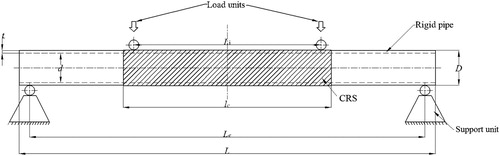
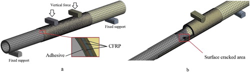
The FE analysis is conducted using the commercial code ANSYS workbench 19 (ANSYS Citation2018). The model conforming to the experimental setup of the studies by Kabir et al. (Citation2016) and Yoo and Ando (Citation2000) subjected to four-point bending are developed for the validation purpose. The FE model includes the cracked steel pipe, CRS on the steel pipe, load and supports units. The steel pipe is horizontally positioned, supported by two semi-roller units whose bottoms are fixed supported, as shown in . Three layers of CFRP laminates are wrapped around the pipe specimen. The contact surfaces of different layers (e.g. between steel and adhesive layer, adhesive layer and CFRP, and different CFRP laminates) are bonded – no sliding or separation is allowed. The contact of load units to pipe/CFRP and pipe to support units adopts the no separation contact which do not allow penetration or separation of contact surfaces but allows sliding in the tangent. A pair of symmetrical vertical forces is applied on the load units, generating a bending moment on the pipe model. The size of the pipe and composite, and their material properties will be introduced in Section 2.2, because these parameters are complying with the test specimens from two different literatures.
Figure 1. The schematic of the FE model and the 4-point bending setup.
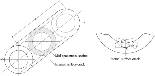
The internal surface crack is introduced to the bottom mid-span of the pipe, as shown in . The surface crack is circumferentially oriented in the cross-section plane, as a semi-elliptical shape. The profile of the surface crack is determined by the crack depth a, and the half crack length c. The eccentric angle is adopted to define different point along the crack front. Note that in this study, the value of
can be smaller than 0 or larger than
due to the inner curved pipe surface.
Figure 2. The location of the surface crack and the parameters of the surface crack.
A sensitivity study has been conducted in a previous work to determine the appropriate modelling strategy (e.g. element type, meshing method and size, modelling contours and divisions around crack tip) in order to ensure the accuracy of SIF evaluation (Li et al. Citation2019). (a) shows the FE mode and the global meshing condition. The 20 nodes solid element ‘solid 186’ is adopted to build the FE model. Two different meshing strategies are applied to the pipe: tetrahedral meshing method is used for the middle part where the crack is located; while sweep meshing method is applied for the other two parts. Sweep meshing method is used for the FRP laminates, and the support/load units as well. In this paper, to ensure a robust and efficient evaluation, a 5.0 mm body element size is used for the areas of the pipe around the surface cracks and the CRS laminates, a 15.0 mm edge size is used for the rest of the pipe model. For the CRS reinforcing laminates, we adopted a 4.0 mm body element size for the adhesive layer, and a 5.0 mm body element size for the CRS laminates.
Figure 3. (a) Global mesh of the FE model and the CFRP reinforcement; (b) illustration of the surface cracked area by splitting the pipe.
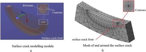
The surface crack is modelled by deploying the Semi-elliptical Crack module (ANSYS Citation2018) in ANSYS workbench, as shown in (a). Six contours with eight divisions for each contour are modelled around the crack tip to ensure an accurate prediction of the SIF. The diameter of the largest contour is 1.0 mm, which makes the element size around the crack front smaller than 0.2 mm. The meshing condition around the internal surface crack adopts the tetrahedral meshing method, while around the surface crack front (e.g. the contour around the crack front) employs hexahedra dominant meshing method to form well-ordered concentric contours, in order to achieve a rational prediction of the SIF.
Figure 4. (a) Surface crack modelling module; (b) the mesh around the surface crack.
2.2. Validation of the numerical method
On account of the fact that it is hard to find available experimental/numerical data of surface crack growth in pipe reinforced with CRS subjected to bending in open documents, the FE model is validated in two phases by using experimental data of intact pipe reinforced with CRS and surface crack growth in steel pipes respectively. The two phases separately validate the pipe mechanical response of the pipe owing to CRS reinforcement, and the SIF evaluation of surface cracks in pipe subjected to bending, as the two key components, in order to ensure the accuracy of the FE model. It should be noted that the validation is based on the assumption that no interfacial failures or adhesion failures will occur to the FE model. Therefore, the investigations and analysis towards the SIF response owing to CRS reinforcement are based on this assumption.
2.2.1. Validation of phase one: intact pipe reinforced with CRS subjected to bending
The aim of phase one is to validate the mechanical transmission between the pipe and the composite layers. Three groups of experimental results (conforming to the specimens ‘B2_US’, ‘S5B-1’, and ‘S6B-2’ in the referred study) of intact pipes reinforced with CRS subjected to bending from the study by Kabir et al. (Citation2016) are applied, as listed in . The FE models include one intact pipe without reinforcement, and two CRS reinforced steel pipes using different CFRP wrapping scheme, as shown in . The pipe steel has an elastic modulus of 214 GPa, and its yield strength and tensile strength are 327 and 383 MPa respectively. The material properties of CFRP and adhesive are listed in . The thickness of the each CFRP laminate is 0.6 mm, while the thickness of the adhesive layer is 0.35 mm, as shown in (a). Notice that all the setup and material properties in phase one are conforming to the research by Kabir et al. (Citation2016).
Figure 5. Wrapping pattern including longitudinal direction (L) and hoop direction (H).
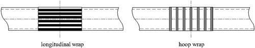
Table 1. Detail information of the phase one FE models.
Table 2. Material properties of the adhesive and CFRP (Kabir et al. Citation2016).
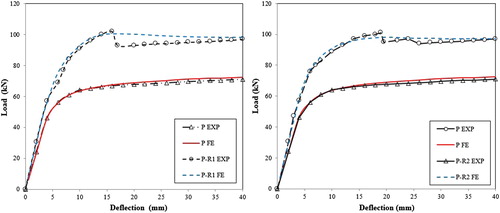
Two vertical loads are applied on the loading units of the FE models under displacement control condition at a constant rate, as shown in . The service load of the referred tests was in accordance with the code (AS Citation2001). Then the mid-span displacement is calculated by means of the FE method, and the results of load-displacement curves are compared with the experimental data.
shows the numerical and experimental load-displacement responses for the bare pipe models and the CRS reinforced pipe models. It shows that the FE results match well with the experimental data until the load reaches the peak value. Then the load suddenly decreases due to debonding, which is not predicted by the FE models because interfacial failure is not considered. However, in the linear-elastic zone for crack growing under high-cycle fatigue condition, the FE method is able to accurately predict the load-displacement response for both bare and CRS reinforced pipes. It means that the FE model is appropriate to simulate mechanics transmission within the composite layers and the steel pipes subjected to bending.
Figure 6. Numerical and experimental (Kabir et al. Citation2016) load–displacement response of P, and (a) P-R1, (b) P-R2.
2.2.2. Validation of phase two: circumferential internal surface crack growth in pipe subjected to bending
The purpose of phase two is to validate the feasibility of the FE model to evaluate the SIF of circumferential internal surface cracks in steel pipes subjected to bending. The FE model is validated by six groups of experimental results from the research by Yoo and Ando (Citation2000), as listed in . In this phase, only pipe material is considered. Its elastic modulus is 200 GPa, yield stress is 227 MPa and tensile strength is 406 MPa. Note that the setup and material properties in phase two are conforming to the research by Yoo and Ando (Citation2000).
Table 3. Detail information of phase two FE models.
Since the reference by Yoo and Ando (Citation2000) provides the data of the maximum stress of the pipe subjected to bending (see in ), therefore the maximum value of the fatigue load applied on the load units P is determined as
(1)
(1) The calculated P is applied on the load unit to generate a bending moment to the bare pipe, and the SIF of the deepest point and surface point of internal surface cracks are calculated by the FE models, using the contour integral method. Incorporating with the Paris’ law, surface crack growth rate along the depth and length direction are predicted by
(2)
(2)
(3)
(3) where
and
are the crack growth rate along the depth and length direction respectively (unit in mm/cycle). C and m are Paris’ constants, which are
and 3.72 respectively (unit in MPa/m1/2) (Yoo and Ando Citation2000),
and
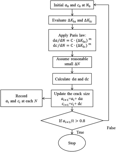
are the SIF range of the deepest point and the surface point of the crack. Afterwards, by assuming a small amount of cycles, the increments of the crack length and depth are calculated. Eventually, it is possible to trace the surface crack growth along the two directions. The detailed procedure of evaluating surface crack growth is indicated in .
Figure 7. The procedure of evaluating surface crack growth.
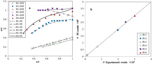
The FE results are compared with the experimental data of a/c versus a/t ratio and fatigue life of the specimens, as shown in . The comparisons of a/c versus a/t ratio in (a) show that the FE methods are able to predict the crack shape variation during the crack growth process. The good agreement of fatigue life predictions between the experimental and FE method in (b) illustrated that the FE method is able to accurately evaluate the residual fatigue life. Therefore, the validation illustrates that the FE models provide reasonable SIF evaluations of circumferential internal surface cracks in steel pipes subjected to bending.
Figure 8. Comparison between the experimental results (Yoo and Ando Citation2000) and FE results: (a) a/c versus a/t ratio; (b) fatigue life.
In summary, the two phases validation indicated that the FE method is able to accurately evaluate the mechanics response of CRS reinforced steel pipe in linear-elastic zone and the SIF response of circumferential internal surface cracks in steel pipe. Therefore, since the surface cracks do not contact the CFRP reinforcement layers and assuming no interfacial failures and adhesion failures, the combined FE model – circumferential internal surface crack in steel pipes reinforced with CRS subjected to bending – is able to rationally predict the SIF.
3. A case study
Based on the validated FE model, a new FE model is developed to evaluate the SIF of circumferential surface cracks in steel pipes reinforced with CRS subjected to bending. The CRS material and reinforcing scheme (e.g. layers, wrapping orientation) in Section 2.2.1 are adopted to reinforce the surface cracked steel pipe in Section 2.2.2. The material properties and model size are identical to the corresponding models in Section 2.2. The geometry, model setup and material properties of the steel pipes are identical to FE model ‘PI-6’, while the material properties of CFRP and adhesive are identical to the FE model of ‘P-R1’. The 600 mm long CFRP material was used to reinforce the internal cracked steel pipe with the ‘L-L-H’ wrapping scheme (as the same as model ‘P-R2’). The new FE model is named as ‘PI-R’ and its SIF is calculated through the validated FE model. Afterwards, combined with the procedure in , the surface crack growth rate of both ‘PI-6’ and ‘PI-R’ is predicted. Then assuming a small amount of cyclic numbers, the crack extension value along the length direction and the depth direction are calculated. Notice that the stress ratio is assumed to be R = 0.1 for the evaluation of the crack growth rate.
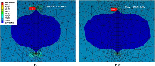
shows the global equivalent stress of the steel pipe of ‘PI-6’ and ‘PI-R’. More detailed, the equivalent stress distributed around the internal surface crack on the pipe internal surface as a butterfly shape is shown in . It illustrates that by means of CRS, the stress concentration around the internal surface crack decreases significantly. Particularly, the stress concentration area around the two surface points of the surface crack, i.e. point B in , becomes smaller owing to the CRS.
Figure 9. The global equivalent stress distribution of the pipe.
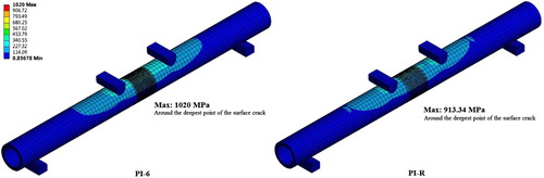
Figure 10. The equivalent stress distribution around the surface crack on the pipe internal surface.
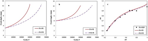
shows the crack growth results of ‘PI-R’ and its comparison with ‘PI-6’. It demonstrates that the CRS significantly decreased the crack growth rate of the internal surface crack along both depth direction (see (a)) and length direction (see (b)). Thus, the CRS increased the fatigue life of the cracked steel pipes. The fatigue life of the unreinforced steel pipe ‘PI-6’, i.e. the cycles when the surface crack penetrating the pipe wall, predicted by the FE method is 298,869, matching well with the experimental results of 287,500 cycles (3.95% error). Owing to the CRS, the fatigue life increased to 439,448, or 47.04%. When the surface crack penetrates the wall, the crack length 2c of ‘PI-R’ is approximately the same with the crack length of ‘PI-6’, indicating that the CRS reinforcement did not change the crack profile. It is also illustrated in (c) that the variation of aspect ratio a/c of ‘PI-R’ kept the same as the aspect ratio variation of ‘PI-6’. The reason is that CRS decreases the crack growth rate approximately equally along the depth direction and the length direction.
Figure 11. The comparison results between the un-reinforced FE model ‘PI-6’ and the CRS reinforced FE model ‘PI-R’: (a) crack growth rate along depth direction; (b) crack growth rate along length direction; (c) a/c versus a/t ratio.
4. Parametric study
In a previous study, researchers indicated that influential parameters of CRS reinforcement, i.e. bond length, numbers of composite layer, CFRP tensile modulus, adhesive thickness, types of adhesive, CFRP wrapping orientation, and pipe dimensions may affect the strength of the reinforced pipes (Kabir et al. Citation2016). However, the understanding of their effects on the SIF of circumferential internal surface cracks is lacking. Regarding this, a range of parametric study has been conducted using the validated FE model to quantitatively analyse their effects. The parametric study is conducted on the pipe in Section 3 with the initial crack size of a = 3.0 mm and c = 6.0 mm, except Section 4.9 which analyses the effect of the dimension of the pipe on the SIF reduction. The reinforcement scheme follows the ‘L-L-H’ wrapping pattern except Section 4.6 when analysing the effect of CRS wrapping orientation, and Section 4.8 when analysing the effect by adding one GFRP layer. It should be noted that a hoop orientated CRS is always applied as the outer layer in light of practical application, because the hoop orientated composite laminate may help to compress the inner layers thus providing a more robust adhesion condition for the CRS reinforcement system. For all FE models, the SIF is transformed into the normalised SIF to better illustrate the effect of the influential parameters on the SIF, which is the quotient of the SIF along the crack front K and the SIF of the deepest point of the surface crack
(the largest SIF for this crack), calculated as
(4)
(4)
4.1. CRS bond length
The CRS bond length is one of the easiest parameters to be changed in practice which affects the budget and time-consuming of the project. In addition, it can significantly influence the reinforcement effectiveness. The main purpose of this section is to find a sound and cost-effective bond length for practical usage. The bond length will be applied for further parametric studies as well. In this study, besides the 600 mm bond length, we investigated the bond length ranging from 50 mm to 600 mm. The FE models therefore are named as ‘PI-R-L50’, ‘PI-R-L100’, ‘PI-R-L150’, ‘PI-R-L200’, ‘PI-R-L400’, and ‘PI-R-L600’ respectively. The number in their names represents the bond length.
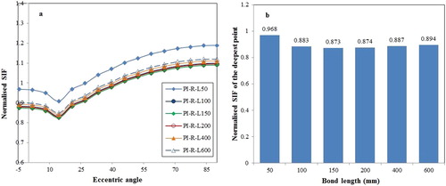
(a) shows the results of normalised SIF along the crack front of the FE models using different bond length. The SIF of ‘PI-R-L50’ is remarkably larger than the other FE models. The possible reason is the lack of effective bond length. The SIF decreases within the increasing of the bond length until it reaches 150 mm. Then the normalised SIF basically remains constant within the increasing of bond length. The reason is that once the bond length reaches a sufficient value, the bending moment remains basically stable within the increasing of the bond length, thus its effect on the SIF reduction is negligible. Overall, the SIF along the crack front of the FE models with the bond length from 100 mm to 600 mm do not have significate differences, as illustrated in (b). The FE model ‘PI-R-L150’ has the smallest SIF; therefore 150 mm bond length is selected as a most efficiency and cost-effective bond length, which is applied in the following parametric studies.
Figure 12. The normalised SIF result of FE models with different bond length: (a) normalised SIF along the crack front; (b) normalised SIF of the deepest point.
Besides the pipe in this FE model, which has an external diameter of 102 mm, the possible relation between the optimum bond length and the external diameter of the pipe is discussed. The diameter ranging from 102 mm to 273 mm as some of the common used offshore pipeline specifications (API Citation2018) of the FE models are listed in . The thickness of the pipes is kept constant as 12.7 mm. It shows that the optimum bond length for pipes with larger external diameter has been increased. For instance, the optimum bond length for the pipe with the diameter of 102 mm is approximately 150 mm, as well as for the pipe with diameter of 168.3 mm. While for pipe diameter of 219.1 and 273.0 mm, the optimum length increases to 200 mm. When reinforcing steel pipes with larger diameter, the bond length needs to be increased correspondingly. The optimum bond length for a specific steel pipe should be further determined by means of a sensitive study based on its dimension.
Table 4. Specimen configuration of steel pipes with various diameters and thickness, and the SIF decrease.
4.2. Numbers of composite layer
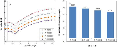
Changing the numbers of composite layer is another practical way to affect the budget, time-consuming and reinforcement effectiveness. In this section, the influence of composite layers by using four different ranges of longitudinal CFRP layers is analysed. CRS bond length of 150 mm is chosen based on the study in Section 4.1. The FE models are named as ‘PI-R-LH’, ‘PI-R-LLH’, ‘PI-R-LLLH’, and ‘PI-R-LLLLH’.
(a) shows that the normalised SIFs decrease equally along the crack front by increasing the numbers of composite layer of longitudinal CFRP. (b) shows that SIF of the deepest point decreases by increasing the numbers of composite layer. Theoretically, the SIF is able to be decreased to a smaller value than the threshold value. In practical situations, users are able to design the numbers of composite layer based on requirement of the life extension. In this case, adding one layer of longitudinal CFRP from ‘PI-R-LLH’ to ‘PI-R-LLLH’ deceased the SIF approximately 6%.
Figure 13. The normalised SIF result of FE models with different numbers of composite layer: (a) normalised SIF along the crack front; (b) normalised SIF of the deepest point.
4.3. CFRP tensile modulus
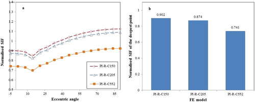
The material properties of CFRP have been rapidly developed thanks to the development of material technology. One of the most important material properties of CFRP is the tensile modulus. To date, the global market provides CFRP materials with different tensile modulus. In this section, we investigate three different CFRP materials with the tensile modulus of 150, 210 and 552 GPa respectively. The FE models are named as ‘PI-R-C150’, ‘PI-R-C210’ and ‘PI-R-C552’.
(a) shows that using the CFRP with higher tensile modulus have enhanced the effectiveness of the CFRP reinforcement. Compared to the normal CFRP with tensile modulus of 205 GPa which decrease the SIF of 12.6%, the SIF of ‘PI-R-C150’ decreases 9.8%, while the SIF of ‘PI-R-C552’ decreases 25.9%, as shown in (b). Therefore, high tensile modulus CFRP can be applied as an alternative of using more composite layers, in order to avoid adding excessive dead weight.
Figure 14. The normalised SIF result of FE models with different CFRP modulus: (a) normalised SIF along the crack front; (b) normalised SIF of the deepest point.
4.4. Adhesive thickness
The adhesive layer acts as intermediary between different layers of the CRS, particularly between the steel pipe and the first composite layer. In addition, the adhesive layer is the weakest layer in the reinforcement system. In practice, changing adhesive thickness might influence the reinforcement effectiveness. In this section, three different ranges of adhesive thickness are analysed, 0.2, 0.35 and 0.5 mm.
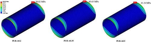
illustrated that the effect on the SIF of surface cracks by changing the thickness of the adhesive layer is negligible. However, increasing the thickness decreases the stress concentration in the adhesive layer, particularly at the edge of the bond, as indicated in . The maximum stress value of the adhesive layer in model ‘PI-R-A0.2’ is larger than the yield stress of adhesive material, which instantly leads to edge debonding failure. A minimum thickness should be identified to avoid such failure. The maximum stress decreases when increasing the adhesive layer thickness, which is helpful to avoid unexpected edge debonding failures.
Figure 15. The normalised SIF result of FE models with different adhesive thickness: (a) normalised SIF along the crack front; (b) normalised SIF of the deepest point.
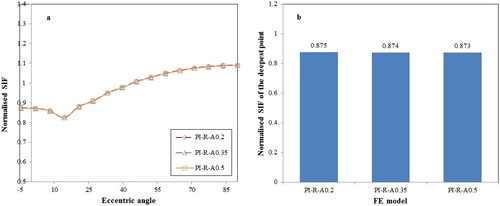
Figure 16. The stress distribution in the adhesive layer with different thickness.
4.5. Type of adhesive
In global market, various types of adhesive are available. In accordance with the research by Kabir et al. (Citation2016), in this part, three types of adhesive are chosen for this study. The types of adhesive and their material properties are shown in . The thickness of all adhesive types is set as 0.35 mm. The SIF results of the FE methods using three different types of adhesive are shown in . It shows that the material properties of adhesive have a minor influence on the SIF of the surface cracks. However, the maximum stress of the adhesive layer using ‘Araldite K630’ and ‘Sikadur 330’ have reached 62.84 and 56.03 MPa respectively (see in ). Edge debonding will be triggered. Therefore the ‘MBrace saturant’ adhesive, which has a lower elastic modulus and higher yield strength, is suggested for usage in terms of its lower stress concentration around the edge of the reinforcement.
Figure 17. The normalised SIF result of FE models by using different types of adhesive: (a) normalised SIF along the crack front; (b) normalised SIF of the deepest point.
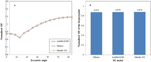
Figure 18. The stress distribution in the adhesive layer using different types of adhesive.
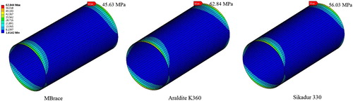
Table 5. Material properties of different type of adhesive (Kabir et al. Citation2016).
4.6. CFRP wrapping orientation
Normally in market, the principle direction of unidirectional CFRP is the longitudinal direction. However, in practice, longitudinal wrapping is difficult to be employed, especially for underwater scenario and for pipes with large external diameter. In this section, the ‘L-L-L-H’ wrapping pattern with an inversely diagonal wrapping pattern, i.e. -
-
-
wrapping, and L-H-L-H wrapping pattern, are compared, as shown in . The FE models are named as ‘PI-R-LLLH’, ‘PI-R-In.’ (inversely diagonal wrapping pattern), and ‘PI-R-LHLH’ correspondingly. In addition, the results of these FE models are also compared with ‘PI-R-LLH’ as the control model.
Figure 19. Wrapping scheme: (1) longitudinal and hoop wrapping; (2) inversely diagonal wrapping pattern.
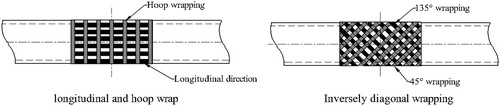
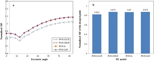
The SIF results in show that using longitudinal CFRP is the most effective way to reduce the SIF of the internal surface crack. The comparison between ‘PI-R-LHLH’ and ‘PI-R-LLH’ in (b) illustrated that adding one hoop oriented CFRP has a minor effect on the reduction of the SIF. It shows that the SIF of ‘PI-R-In.’ model preforms slight better than the ‘PI-R-LHLH’ model. In practical situations when longitudinal wrapping is difficult to be implemented, using the inversely diagonal wrapping pattern is an alternative. However, considering the remarkable SIF reduction, longitudinal orientated CFRP is recommended for practical usage. In global market, it is possible to acquire CFRP material with user-design fibre direction, in order to guarantee CFRP wrapping orientation during the reinforcement, as well as ensure the feasibility of construction.
Figure 20. The normalised SIF result of FE models with different CFRP wrapping orientation: (a) normalised SIF along the crack front; (b) normalised SIF of the deepest point.
4.7. Crack aspect ratio
Surface cracks are commonly induced by mechanical damage, corrosion pitting, and welding defects. They frequently appear on steel pipes with various profiles, mainly represented by their aspect ratios. In this section, the SIF response of internal surface cracks in steel pipes with six different aspect ratios from 0.25 to 2.0 reinforced with CFRP are analysed. shows the crack profile of the specimens, and the results of SIF decrease after reinforcement. The CFRP reinforcement continually adopts the scheme of ‘PI-R-LLLH’. The results indicate that all the SIF of surface cracks with different aspect ratio from 0.25 to 2.0 decreases around 13% owing to the CFRP reinforcement.
Table 6. Specimen configuration of steel pipes with different aspect ratios.
4.8. One added GFRP layer
In practical situation, when using CFRP to repair metallic structures, one layer of GFRP is generally applied in between the metallic substrate and the CFRP laminates in order to prevent the galvanic corrosion. In this part, we use both the GFRP and CFRP to reinforce the internal cracked steel pipe, named as ‘PI-R-GLLH’. The GFRP uses E-glass fibre from the material library of ANSYS workbench, and its properties are listed in . The thickness of the GFRP is 0.35 mm. The SIF is evaluated by means of the FE method and then compared to the results of specimen ‘PI-R-LLH’ and ‘PI-R-LLLH’. The results are shown in , which indicates that adding one GFRP layer is rather effective to reduce the SIF of the surface crack. Comparing to ‘PI-R-LLH’, the SIF of the deepest point decreases 1.6%. Therefore, one-layer GFRP is recommended mainly because of its galvanic corrosion resistance.
Figure 21. The normalised SIF result of FE models by using on one layer of GFRP laminate: (a) normalised SIF along the crack front; (b) normalised SIF of the deepest point.
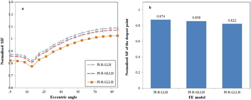
Table 7. Material properties of the GFRP material.
4.9. Dimension of the steel pipe
In this section, eight different pipe dimension with various D/t ratios of API 5L offshore steel pipes, conforming to the code (API Citation2018) are studied using the FE method. lists the configuration of the CRS reinforced steel pipes with various diameter and wall thickness. Diameter of steel pipes from 168.3 mm to 323.8 mm pipes are adopted with five different pipe wall thickness from 10.97 mm to 21.95 mm: five incremental pipe wall thickness has been discussed within the external diameter of 168.3 mm, while four incremental external diameter has been analysed within the pipe wall thickness of 12.7 mm. These pipe dimensions can represent the frequently used steel pipeline in the offshore industry. The reinforcing scheme applies the optimum choices from Section 4.1 to Section 4.7. Therefore, the bond length of all pipes is 150 mm. CRS wrapping scheme adopts ‘G-L-L-L-L-H’, the CFRP laminates adopt the high tensile modulus of 552 GPa, while the adhesive material chooses the ‘MBrace saturant’, with the thickness of 0.35 mm. The crack size of a = 3.0 mm and c = 6.0 mm is applied for this study.
Table 8. Specimen configuration of steel pipes with various dimensions, and the results of the SIF decrease.
The results in illustrates that within the same external diameter, the reinforcement effectiveness (represented by the SIF decrease percentage) decreases with the increasing of wall thickness, and within the same wall thickness, the reinforcement effectiveness decreases with the increasing of pipe external diameter as well. Therefore, when repairing surface cracks in steel pipes with larger external diameter and thicker wall thickness, high elastic modulus CFRP and more CFRP layers are suggested in order to achieve a satisfying decrease of crack growth rate.
5. Conclusions
Circumferential internal surface crack growth is a serious threat to the structural integrity of offshore steel pipes. Critical surface cracks need to be repaired instantly in order to avoid oil and gas leakage. In this paper, CRS is applied to repair the circumferential surface cracked steel pipe subjected to bending. The SIF of the surface crack growth has been evaluated by means of the FE method. Based on the FE method, a parametric study has been conducted. The conclusions are drawn:
CRS is an efficient and cost-effective method to repair internal surface cracks in steel pipes. Its effects on crack growth reduction and fatigue life extension are remarkable. For instance, using ‘L-L-H’ wrapping pattern, which is the specimen ‘PI-R-LLH’, has prolonged the fatigue life of the cracked steel pipe with 47.04%.
CRS decreases the crack growth rate along the depth direction and length direction approximately equally. It means CRS will not change the variation of the crack profile (represented by the variation of the crack aspect ratio) during the crack growth process.
The parametric study indicated the key influential parameters significantly affected the SIF of the CRS reinforced surface crack, including the CRS bond length, numbers of composite layer, CFRP tensile modulus, wrapping orientation, and pipe dimensions. In practical situation, users need to achieve a balance among the fatigue life extension requirement, budget and the dead weight.
The parametric study also indicated that adhesive thickness and adhesive types have negligible influences on the SIF reduction. However, increasing the adhesive thickness and using low elastic modulus adhesive material have reduced the stress concentration at the edge of the adhesive layer. Therefore, users need to apply appropriate thickness and type of adhesive layer in order to avoid unexpected edge debonding failure.
CRS has an approximately identical effect on the SIF decrease of surface cracks with different aspect ratio between 0.25 and 2.0.
One layer of GFRP as the first layer is recommended for preventing galvanic corrosion between the CFRP laminate and the steel substrate. The added layer of GFRP has a minor effect on reducing the SIF of the surface crack.
The analysis, design and prediction of external surface crack growth in composite reinforced steel pipes are being investigated by the authors as a separate topic, owing to the different boundary condition such as the interfacial contact between the area where the external surface crack is located and the composite layers. These results will be analysed and presented in future studies.
Disclosure statement
No potential conflict of interest was reported by the authors.
Notes on contributors
Zongchen Li is a PhD candidate working in the Department of Maritime and Transport Technology (MTT), his current research topic is surface crack growth in CRS-reinforced offshore metallic pipes.
Xiaoli Jiang works as an assistant professor in the Department of MTT.
Hans Hopman is a full professor in the Department of MTT.
ORCID
Zongchen Li http://orcid.org/0000-0003-4784-4684
Xiaoli Jiang http://orcid.org/0000-0001-5165-4942
Hans Hopman http://orcid.org/0000-0002-5404-5699
Additional information
Funding
References
- Achour A, Albedah A, Benyahia F, Bouiadjra BaB, Ouinas D. 2016. Analysis of repaired cracks with bonded composite wrap in pipes under bending. J Pressure Vessel Technol. 138:060909. doi: 10.1115/1.4033449
- ANSYS. 2018. Defines a semi-elliptical crack based on an internally generated mesh to analyze crack fronts by use of geometric parameters.
- API. 1999. API-RP-1111. Design, construction, operation, and maintenance of offshore hydrocarbon pipelines (Limit State Design).
- API. 2018. API SPEC 5L: specification for line pipe. Washington (DC): American Petroleum Institute.
- AS. 2001. AS3600. Concrete structures. Sydney: Standards Australia.
- ASME. 2012. Pipeline transportation systems for liquids and slurries: ASME code for pressure piping, B31.4-2012. American Society of Mechanical Engineers.
- Branco R, Antunes FV, Costa JD. 2015. A review on 3D-FE adaptive remeshing techniques for crack growth modelling. Eng Fract Mech. 141:170–195. doi: 10.1016/j.engfracmech.2015.05.023
- BS. 2015. Petroleum, petrochemical and natural gas industries-Composite repairs for pipework-Qualification and design, installation, testing and inspection. BS EN ISO 24817:2015. British Standards Institution.
- Chen J, Pan H. 2013. Stress intensity factor of semi-elliptical surface crack in a cylinder with hoop wrapped composite layer. Int J Press Vessels Pip. 110:77–81. doi: 10.1016/j.ijpvp.2013.04.026
- Chibueze NO, Ossia CV, Okoli JU. 2016. On the fatigue of steel catenary risers. Stroj Vestn-J Mech Eng. 62:751–756. doi: 10.5545/sv-jme.2015.3060
- DNV. 2008. Riser integrity management. DNV Recommended Practice DNVGL-RP-F206.
- DNV. 2017. Assessment of flaws in pipeline and riser girth welds. DNV Recommended Practice DNV-RP-F108.
- Haedir J, Bambach MR, Zhao X-L, Grzebieta RH. 2009. Strength of circular hollow sections (CHS) tubular beams externally reinforced by carbon FRP sheets in pure bending. Thin-Walled Struct. 47:1136–1147. doi: 10.1016/j.tws.2008.10.017
- Kabir MH, Fawzia S, Chan THT, Gamage JCPH, Bai JB. 2016. Experimental and numerical investigation of the behaviour of CFRP strengthened CHS beams subjected to bending. Eng Struct. 113:160–173. doi: 10.1016/j.engstruct.2016.01.047
- Karbhari VM, LI. 2015. Rehabilitation of pipelines using fiber-reinforced polymer (FRP) composites. Cambridge, United Kingdom: Elsevier. https://doi.org/10.1016/C2013-0-16345-3.
- Kim S, Kim M-H. 2015. Dynamic behaviors of conventional SCR and lazy-wave SCR for FPSOs in deepwater. Ocean Eng. 106:396–414. doi: 10.1016/j.oceaneng.2015.06.039
- Li Z, Jiang X, Hopman H, Zhu L, Liu Z. 2019. An analytical investigation on the circumferential surface crack growth in steel pipes subjected to fatigue bending. Theor Appl Fract Mech. 105:102403. doi: 10.1016/j.tafmec.2019.102403
- Liu J, Qin M, Zhao Q, Chen L, Liu P, Gao J. 2017. Fatigue performances of the cracked aluminum-alloy pipe repaired with a shaped CFRP patch. Thin-Walled Struct. 111:155–164. doi: 10.1016/j.tws.2016.11.008
- Woo KS, Ahn JS, Yang SH. 2016. Cylindrical discrete-layer model for analysis of circumferential cracked pipes with externally bonded composite materials. Compos Struct. 143:317–323. doi: 10.1016/j.compstruct.2016.02.044
- Yoo Y, Ando K. 2000. Circumferential inner fatigue crack growth and penetration behaviour in pipe subjected to a bending moment. Fatigue Fract Eng Mater Struct. 23:1–8. doi: 10.1046/j.1460-2695.2000.00248.x
- Zarrinzadeh H, Kabir M, Deylami A. 2017a. Crack growth and debonding analysis of an aluminum pipe repaired by composite patch under fatigue loading. Thin-Walled Struct. 112:140–148. doi: 10.1016/j.tws.2016.12.023
- Zarrinzadeh H, Kabir M, Deylami A. 2017b. Experimental and numerical fatigue crack growth of an aluminium pipe repaired by composite patch. Eng Struct. 133:24–32. doi: 10.1016/j.engstruct.2016.12.011
- Zhao X-L, Zhang L. 2007. State-of-the-art review on FRP strengthened steel structures. Eng Struct. 29:1808–1823. doi: 10.1016/j.engstruct.2006.10.006