
 ?Mathematical formulae have been encoded as MathML and are displayed in this HTML version using MathJax in order to improve their display. Uncheck the box to turn MathJax off. This feature requires Javascript. Click on a formula to zoom.
ABSTRACT
The results of theoretical studies of the possibilities of using hybrid solid oxide fuel cell–gas turbine (SOFC-GT) systems for marine power plants are presented. A 500 kW auxiliary marine power plant scheme using stacks of SOFCs in combination with a regenerative gas turbine operating with over-expansion based on our recent patent application is proposed. The results of mathematical modelling showed the opportunity to obtain a hybrid scheme efficiency of about 55% with the optimal values of the gas turbine compression ratio 2.0–2.2 and the exhauster compressor ratio 1.3–1.4. The application of the considered hybrid SOFC-GT system gives an increase in electrical efficiency by 19% in comparison with a cycle without a gas turbine. The aerodynamic structure of chemically reacting flows in a combustor is determined, as well as the features of the formation of toxic components during the combustion of SOFC off-gas with very low heating value.
1. Intoduction
The main efforts in the field of marine engineering are currently aimed at increasing the energy efficiency of the production, transmission, and use of energy, which is possible only if innovations are based on fundamental science achievements, together with the creation and implementation of new, more reliable and durable materials, equipment and technologies. Fuel cells are one of the promising directions for solving problems of providing electric energy to consumers in various complex conditions (Sun et al. Citation2010; Díaz-de-Baldasano et al. Citation2014; Han et al. Citation2015; Chen et al. Citation2017, Citation2018).
There is growing interest in fuel cells for hybrid systems, including the marine power systems (Fuentes and Pérez Citation2015; Minnehan and Pratt Citation2017; Pratt and Chan Citation2017; Langfeldt Citation2018). In fuel cells, the electrochemical energy is directly converted into electrical energy without the intermediate conversion step via thermal energy (Vogler and Würsig Citation2010; Welaya and Ammar Citation2013; van Biert et al. Citation2016; Schumacher Citation2018). Thus, they are not subject to the limitations of the Carnot Cycle, and the theoretical electrical efficiency of the fuel cells can reach a high value (i.e. around 70% HHV efficiency at 800°C). One promising type of fuel cell is the solid oxide fuel cell (SOFC), in which a high operation temperature (600–1100°C) takes place (Vogler and Würsig Citation2010; Welaya and Ammar Citation2013; Han et al. Citation2015).
SOFCs have a wide range of applications, from portable current power sources (10–300 W) to autonomous stationary power plants (1–10 MW and more). Their strengths are primarily due to the high efficiency of the direct conversion of the fuel chemical energy into electricity. In this case, almost any hydrocarbons can be used as fuel, and air as an oxidising agent. Solid oxide fuel cells in particular offer high fuel flexibility for various gases and liquids, e.g. methane, ethanol, methanol, propane, LPG, diesel, DME, ammonia, and more (Baldi et al. Citation2020). Many of the investigated systems refer to the use of SOFCs in combination with an external reformer. Therefore, the limitation in the use of liquid fuels, widely used in ship power plants: HFO, MDO, and MGO, is determined mainly by issues of workability and efficiency of reformers, as well as their sensitivity to sulfur compounds.
Moreover, electrochemical fuel oxidation provides high environmental friendliness of the power generating process. It allows the SOFC to be put into practice with a gas turbine to produce electrical and thermal energy in hybrid cycles. These hybrid cycles will be competitive with traditional complicated cycles consisting of a gas turbine and a heat recovery steam generator, because the electrical efficiency of the whole system may reach 70% and more (Lemański et al. Citation2004; Cheddie Citation2010; Saisirirat Citation2015; Tunca and Kaya Citation2017; Zaccaria et al. Citation2017).
The SOFC-GT efficiency is unique in being practically independent of scale, and systems have been demonstrated with 50–60% efficiency even at one kilowatt of delivered power (McPhail et al. Citation2012). As an example, Siemens Westinghouse has developed a pressurised 220 kW SOFC-GT hybrid system using tubular SOFC stacks (National Fuel Cell Research Center Citation2010). The system was designed, constructed, and tested to demonstrate and prove this hybrid concept by operating for at least 3000 h at the National Fuel Cell Research Center of the University of California, Irvine.
It is generally agreed that the marine industry may have a wide variety of applications for fuel cells with various power outputs.
Fuel cells have a significantly higher efficiency than traditional power plants with internal combustion engines and gas turbines. However, the specific requirements and some technical problems limit the application of fuel cells in marine engineering. Currently, many fuel cells for marine power plants are still in the R&D and demonstration stages (Han 2015). Designs of the ship power plants where the SOFC takes the largest share of the onboard energy conversion are practically absent. All the studies mentioned in the available literature focus on the use of SOFCs as auxiliary power units, or at most as the minor element of a hybrid system mostly based on Diesel engines (Baldi 2020).
Currently, some research projects focus on SOFC associated with a reformer which can use standard liquid or gaseous fuels. Díaz-de-Baldasano et al. (Citation2014) reported the conceptual design of a platform supply vessel with an innovative hybrid diesel-electric-fuel cell-driven propulsion, which was called Balmat. Two 250 kW high-temperature SOFC systems working with methanol were integrated within the ship supplying electrical energy. Cherednichenko and Serbin (Citation2018) and Cherednichenko et al. (Citation2019) analysed the capabilities of thermo-chemical technologies for the conversion of different hydrocarbons on ships. As reported by Sun et al. (Citation2010), the SOFC-GT system for the Large Medium Speed Roll-on/Roll-off sealift ship has significant potential in reducing nitrogen oxides emission and fuel consumption. Four SOFC modules and one gas turbine generator with a special catalytic combustor were proposed to construct a hybrid SOFC-GT engine with 24 MW of total electrical power.
Langfeldt (Citation2018) reported the prospects of using high-temperature molten carbonate (MCFC) and SOFCs with electrical efficiency above 50% for marine applications. Several commercial vessels have been proposed with molten carbonate and SOFCs operating on methanol or natural gas. In 2006, a methanol-fuelled 20 kW SOFC plant was tested on board the car carrier ‘Undine’; an LNG fuelled 330 kW MCFC plant was installed on board the ‘Viking Lady’ (FellowShip project) 2003–2011; an SOFC installation was tested on the commercial vessel ‘MS Forester’ during the SchIBZ2 project 2017–2021; Germany is funding the Lighthouse project e4Ships for maritime fuel cell application 2009–2021; and lengthy fuel cells tests are being conducted on board the ‘MS Mariella’ according to project Pa-X-ell2 2017–2021.
To satisfy the requirements of maritime organisations, the thermodynamic analysis of natural gas and hydrogen-fuelled SOFC efficiency was presented (Welaya and Ammar Citation2013). The main parameters which affect SOFC-GT power plant are the compression ratio, air mass flow rate, SOFC fuel utilisation factor, cell voltage, etc. The progress of the infrastructure of LNG vessels is contributing to the development of fuel cell technologies using natural or associated gases. Therefore, the development of a marine LNG-fuelled SOFC combined system will be taken up in the recently announced Dutch national GasDrive project (van Biert et al. Citation2016).
An overview of the e4ships project and its components (SchiBZ, Pa-X-ell, RiverCell, ELEKTRA) is presented by Schumacher (Citation2018). It is planned to use low sulphur diesel, methanol, hydrogen, and LNG as fuels for the fuel cells. A hybrid SOFC-GT power system model was developed by Saisirirat (Citation2015). The power system efficiency is highly dependent on the operating temperature, air mass flow rate, and heat exchanger properties. A thermo-economic model (Cheddie Citation2010) was developed to optimise an SOFC-GT hybrid power plant for providing different types of electrical power. The results showed that the overall thermal efficiency of a hybrid 37 MW power plant could be increased from 30.0% to 66.2%. A mathematical model for the SOFC with an inverted pressurised Brayton cycle was evaluated (Lemański et al. Citation2004). The impact of fuel cell degradation on the system efficiency was analysed by comparing standard SOFC and hybrid SOFC-GT cycles (Zaccaria et al. Citation2017). An SOFC-GT aircraft auxiliary power unit was thermodynamically investigated by Tunca and Kaya (Citation2017). The onboard kerosene fuel is converted to H2 and CO in the special fuel reformer. Fernandes et al. (Citation2018) present the results of studies of design, development, and testing of the SOFC system with a gasifier, which is used as a plasma reactor that processes 8.84 kW of waste. We note the prospects for using plasma technology not only for the gasification of various hydrocarbons but also for organising efficient afterburning of the fuel cell off-gases (Gatsenko and Serbin Citation1995; Matveev et al. Citation2007a, Citation2015; Matveev and Serbin Citation2012). A membrane-based reformer–combustor reactor for hydrogen generation is proposed and numerically investigated by Sanusi and Mokheimer (Citation2019). The burning behaviour for the demonstrator SOFC system was investigated using an atmospheric combustor test rig at the German Aerospace Centre (Lingstädt et al. Citation2018). Additionally, a strategy for flame stabilisation for fuels with very low heating values was tested.
The presented by Kwaśniewski and Piwowarski (Citation2020) 10 MW hybrid system is a thermodynamic combination of two power systems: a gas turbine and fuel cell (stack). Linking these systems together makes it possible to generate much more useful energy than in the case of individual operation of these devices at the same fuel consumption.
The adoption of fuel cell technology on the ship will firstly take place in the replacement of auxiliary power plants. In the presented article, we propose a new scheme of an auxiliary hybrid SOFC-GT marine system that allows the reduction of the working pressure in the SOFC stacks due to the use of an innovative solution: a regenerative gas turbine operating with over-expansion. First, a mathematical model of the power system’s gas-turbine part will be described; then the results of the analysis of the thermodynamic efficiency of a hybrid SOFC-GT system will be presented, and the possibility of the SOFC off-gas afterburning in a gas turbine combustor will be analysed.
2. Mathematical model of a hybrid SOFC-GT system
Based on our patent application (Serbin et al. Citation2020), the hybrid power plant with fuel cells, which contains a fuel reformer, a stack of solid oxide fuel cells, a regenerative gas turbine engine as part of a turbocharger unit, regenerative heaters and a combustor connected to the outlet of solid oxide fuel cells, differs in that a gas cooler and an exhauster are installed behind the turbine part of the gas turbine engine. This solution allows the pressure in the reformer to be reduced, creating more favourable conditions for fuel conversion processes and enabling more efficient use of the thermal potential of the gas mixture at the outlet of the fuel cells.
shows a 500 kW auxiliary marine power plant using the SOFC stack in combination with a regenerative gas turbine operating with over-expansion.
Figure 1. Diagram of a marine electric power plant using SOFC stacks in combination with a regenerative gas turbine operating with over-expansion: 1. electric generator; 2. compressor; 3. turbine; 4. exhauster; 5. gas cooler; 6. regenerator; 7. air superheater; 8. circulation pump; 9. ejector supply of associated gas; 10. preliminary reformer; 11. built-in reformer; 12. combustor; 13 (1), 13 (2). DC-AC inverters; 14. AC-DC inverter; A. atmospheric air; G. exhaust gases; F. fuel supply (associated gas).
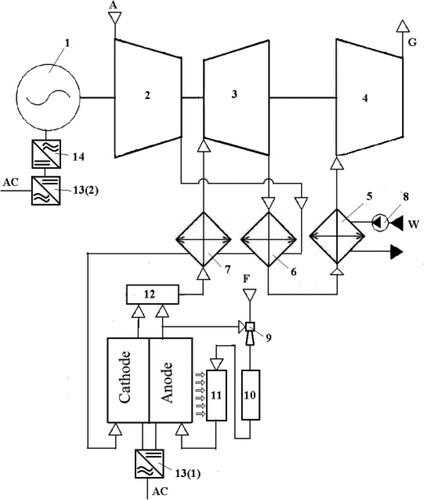
For the considered SOFC-GT complex, a thermodynamic scheme with heat recovery of the exhaust gases from a turbine operating with over-expansion has been adopted. The gas turbine can reduce the pressure in the SOFC stack to the minimum values – not higher than 0.18–0.20 MPa.
Atmospheric air is compressed by a compressor ‘2’ to the estimated value and passes through a regenerator ‘6’, in which it is preheated by the exhaust gases of turbine ‘3’. Turbine ‘3’ drives compressor ‘2’, exhauster ‘4’, and the excess turbine power is transferred to electric generator ‘1’. After the regenerator, cyclic air enters the air superheater ‘7’ and overheats to a predetermined temperature at the SOFC cathode inlet by gases exiting combustor ‘12’. The fuel for combustor ‘12’ is the mixture of gases from the SOFC anode outlet, which burned in oxygen-depleted air entering the combustor from the SOFC cathode outlet. Cooled to a certain temperature, the combustion products after superheater ‘7’ enter turbine ‘3’, where they expand to a pressure significantly lower than atmospheric. The pressure level is determined by the estimated value of the exhauster ‘4’ compression ratio. Then gases after turbine ‘3’ pass through the gas side channels of regenerator ‘6’ and enter gas cooler ‘5’, where they are cooled by water to the estimated value. The cooled gases are compressed in exhauster ‘4’ and discharge into the atmosphere.
A mathematical model of a hybrid SOFC-GT auxiliary marine system has been developed, including two models: (a) a model of a regenerative gas turbine with over-expansion, and (b) a model of the SOFC stack.
A specific feature of a gas turbine mathematical model for the considered hybrid SOFC-GT system is that we cannot accept, as is usually done in gas turbine engine design, the gas turbine inlet temperature. In our case, the value of this parameter will be determined by the given value of the superheated air temperature at the SOFC stack inlet at nominal operating mode
, the value of the regeneration coefficient
and the compression ratio
. The gas temperature at the combustor exit is determined by the formula
(1)
(1) where
is the relative fuel consumption in the combustor (the ratio of the mixture flow rate at the output from the SOFC anode to the flow rate at the output from its cathode),
is the operating temperature of the SOFC stack,
is the stoichiometric amount of depleted air at the outlet of the SOFC cathode,
is the lower heating value of the gas mixture at the outlet of the SOFC anode,
is the combustion efficiency,
is the average mass isobaric heat capacity of stoichiometric combustion products for the process temperature
in the combustor,
,
are the average mass isobar heat capacity of air for the process temperatures
and
in the combustor, respectively.
In this case, the gas temperature at the gas turbine inlet will be determined as follows:
(2)
(2) where
,
are the average mass isobar heat capacities of air and combustion products for heat transfer processes in the superheater,
,
are the average mass isobar heat capacity of air and combustion products for heat transfer processes in the regenerator,
is the air temperature behind the compressor,
is the exhaust gas temperature.
The calculated powers of the compressor, turbine, and exhauster for one SOFC stack will be, respectively,
(3)
(3)
(4)
(4)
(5)
(5) where
,
,
are the gas turbine compression ratio and the exhauster compressor ratio, as well as the pressure reduction ratio in a gas turbine, respectively,
,
,
are the internal adiabatic efficiency of the compressor, exhauster and turbine, respectively,
is the air flow through the compressor,
is the air temperature in the compressor inlet,
is the gas temperature in the exhauster inlet,
,
,
are the isentropic indexes for the compressor, exhauster, and turbine, respectively,
,
,
are the average mass isobar heat capacities of air and combustion products for processes in the compressor, exhauster, and turbine, respectively.
The electrical power of the gas turbine part is
(6)
(6) where
,
,
are the efficiency of the gearbox, generator, and inverter, respectively.
The electrical power of the SOFC-GT system is
(7)
(7) where
is the electrical power of the SOFC stack.
The electrical efficiency of the hybrid SOFC-GT system is
(8)
(8) where
is the hourly fuel (associated gas) consumption at the SOFC stack inlet.
The gas turbine used is considered for the power range up to 200 kW, therefore the efficiency of its elements is adopted corresponding to the level of existing micro-turbines technology. The following parameters were taken in the calculations: the compressor, exhauster, and turbine efficiency are 0.81, 0.82 and 0.90, respectively.
The adequacy of the developed mathematical model of the gas turbine part of the investigated power system is confirmed by the satisfactory agreement of the calculated parameters of microturbines with the regenerative cycle obtained by mathematical modelling with the manufacturer's published data. The results of verification for three Capstone gas turbine units C30, C65, and C200S (Gimelli and Sannino Citation2017; Capstone Turbine Corporation Citation2020) at the nominal operation mode are presented in .
Table 1. Results of verification of the gas turbine part’s model.
The tubular Siemens Westinghouse SOFC stack design (National Energy Technology Laboratory Citation2004; National Fuel Cell Research Center Citation2010) is taken as a basic element of the scheme. summarises the assumptions made for the fuel cell model. The efficiency of the SOFC stack is estimated for associated gas with the lower heating value Hu = 44000 kJ kg−1. The associated gas composition (Nguyen et al. Citation2012) is adopted for calculations as follows (vol. %): CH4 = 73.7, C2H6 = 6.1, C3H8 = 6.7, C4H10 = 7.79, N2 = 4.37, CO2 = 1.34. The associated gas assumed as a fuel for Floating Production, Storage, and Offloading (FPSO) vessels (Cherednichenko et al. Citation2019).
Table 2. Assumptions for the SOFC stack mathematical model.
3. Investigation of thermodinamic parameters of a hybryd SOFC-GT system
shows the dependences of the hybrid scheme’s efficiency depending on the gas turbine compression ratio for several values of the exhauster compression ratio. At the same time, the inlet gas turbine temperature changes following the graphs shown in .
Figure 2. Efficiency of the SOFC-regenerative gas turbine with overexpansion hybrid scheme.
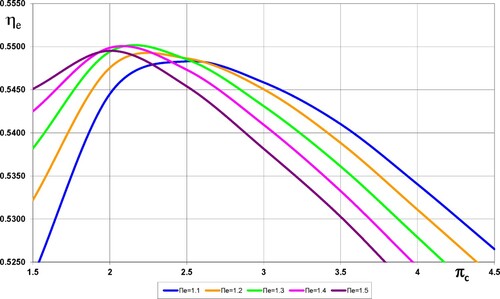
Figure 3. Gas turbine inlet temperature in a hybrid power generation system.
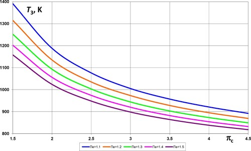
The results of mathematical modelling using existing micro-turbines with a power of 60–200 kW show that it is possible to obtain a hybrid scheme efficiency of about 55% with the optimal values of the gas turbine compression ratio 2.0–2.2 and the exhauster compressor ratio 1.3–1.4. Since the efficiency of the direct conversion of all fuel energy into electrical energy by the stack under consideration is 46.24%, the application of the considered hybrid SOFC-gas turbine scheme with over-expansion gives an increase in the electrical generation efficiency by approximately 19%. At the same time, the gas turbine inlet temperature is 1050–1090 K.
shows the change in the total power generation in the hybrid scheme depending on the gas turbine compression ratio for several values of the exhauster compression ratio.
Figure 4. The total power of a hybrid scheme (kW) per 1 stack.
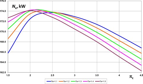
With the above optimal scheme parameters, it is possible to obtain additional power in the gas turbine of 27.5–27.7 kW per stack, which allows a maximum total electric power of the complex of approximately 174.0 kW per stack.
The main parameters of the thermal scheme of the hybrid SOFC-GT marine power plant with a power of 500 kW, calculated under ISO conditions, are shown in .
Table 3. The main parameters of a hybrid SOFC-GT system.
In contrast to the energy systems traditionally used in gas turbine engineering, the proposed regenerative gas turbine operating with over-expansion allows to sharply reduce the optimal compression ratio to 1.95–2.2 ( and ), unlike, for example, the regenerative gas turbine engines Capstone C30, C60, and C200S, which are widely used at present, with compression ratio of 3.5–4.2 (Capstone Turbine Corporation Citation2020). Taking into consideration the fact that in a conventional SOFC-GT cycle with a regenerative gas turbine the optimum compression ratio for the considered initial parameters is about 2.7, the use of a turbine with over-expansion reduces this value to 1.95, i.e. by 27.8%.
This simplifies the compressor part of a gas turbine engine and increases the reliability and lifetime of a regenerator. However, in the considered hybrid cycle, a decrease in the optimal pressure in the cycle most favourably affects the performance, and most importantly, reliability, weight indicators, and lifetime of the fuel cell due to a decrease in the potential for leaks of the working fluid and a simplified design of the fuel reforming system. The use of an exhauster with a compressor ratio of 1.4 (, ) makes it possible to reduce the inlet gas turbine temperature up to 1068 K, which practically justifies the absence of expensive cooling systems for turbine blades and simplifies its operation.
The presence of an exhauster increases the efficiency of the gas turbine part by about 2.1%, and, consequently, the efficiency of the SOFC-GT cycle by 0.37%. The use of an exhauster in the SOFC-GT scheme increases the available heat drop in the gas turbine, which leads to an increase in its power. This also rises the electric generation of the gas turbine engine by about 2%. Note that the share of power generated by a gas turbine engine in the overall hybrid SOFC-GT cycle reaches 16% ().
4. Investigaton of the SOFC off-gas afterburning process
The combustor in the hybrid SOFC-GT system is used after the fuel cell stacks to burn the remaining fuel (generally the fuel utilisation in an SOFC stack is around 80%). The combustor should be specifically designed for a hybrid system or modified from the standard gas turbine combustor. However, the combustor can operate on fuel with a very low heating value and diluting air at high temperatures within a large load range and achieve very low emissions at the same time.
For a preliminary analysis of the SOFC off-gas afterburning possibilities, the design of a traditional diffusion-type individual combustor of the gas turbine engine UGT2500 (Serbin and Goncharova Citation2017) was adopted as an object for investigation (). This gas turbine engine has a remote combustor which consists of two vertically located combustion liners. The combustion liners are telescopically linked with a gas-collector which directs the gas flow from the combustion liners to a high-pressure turbine inlet.
Figure 5. Geometry model of the combustor: (a) longitudinal combustion section; (b) combustion liner.
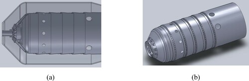
The areas of the flow sections of the fuel nozzle were increased, which provided the required velocity of the SOFC off-gas flow from the fuel holes without flame blow-out. At this stage, apart from the change of the flow sections of the fuel nozzle and secondary air holes, no other design modifications were carried out.
When developing a model of turbulent chemically reacting flows in such a combustor, it is taken into consideration that it should include a number of sub-models of the most important physical and chemical processes: mixture formation of reagents (off-gas and diluted air) up to full molecular homogeneity, turbulent transfer and gaseous fuel combustion including pulsations of component concentrations of the reacting system.
The developed model of chemically reacting flows is based on solving an equation system which describes the convection and diffusion transfer of concentrations for each of the reacting mixture components. A detailed description of the model can be found in (Serbin Citation1998; Matveev and Serbin Citation2006; Serbin Citation2006; Matveev et al. Citation2007b; Serbin et al. Citation2011, Citation2014).
The calculations of the aerodynamic flow structure in the gas turbine combustor were carried out for off-gas of the following composition (mass fraction): = 1.54%,
= 12.36%,
= 21.63%,
= 64.47%. The composition of the diluted air (mass fraction):
= 18.26%,
= 0.96%,
= 80.54%,
= 1.39%.
As a result of calculations with the use of the simplified fuel oxidation mechanism (Serbin and Goncharova Citation2017) in , the data on the distribution of velocities, temperatures, and chemical components concentrations inside the combustor were obtained.
Table 4. Reactions to the fuel oxidation mechanism.
As the represented kinetic mechanism of off-gas oxidation contains a lot of reactions, they require the use of a combustion model capable of predicting the special features of chemical species. The Eddy-Dissipation-Concept (EDC) is such a model which considers the interaction of chemical kinetics and turbulence of the flows (Serbin et al. Citation2011; Cherednichenko et al. Citation2019). The model assumes that the reactions occur in small turbulent structures called small-scale reactors.
The size of the small-scale reactor and the reaction time are defined via the formulas
(9)
(9) where * indicates the small-scale structure.
The value depends on the coefficient of the kinematic viscosity
, kinetic turbulence energy
and the dissipation velocity of the kinetic turbulence energy
.
In this model, the small-scale reactors are the ones of constant pressure whose initial conditions are defined by the concentration of the components and reaction temperature. The reaction velocities are defined via Arrhenius equations and numerically integrated using the special ISAT algorithm. Then the molar velocity of formation/decomposition of the i-th component in the reaction is defined as follows:
(10)
(10) where ρ is the flow density, and
is the mass fraction of the i-th reagent in the reactor after time expiration
.
The reaction time in the reactor is
(11)
(11) where
= 0.4082 is the time constant.
A mathematical model of nitrogen oxides emission is a system of mass transfer equations that include convection, diffusion, formation, and decomposition of NO and related compounds. The influence of the reagent’s residence time in the reaction volume on the mechanism of NO formation is considered in the convection terms of the defining equation (Serbin et al. Citation2011):
(12)
(12) where
is nitrogen oxide density,
is the NO mass concentration,
is the diffusion coefficient,
is the velocity vector,
is the source term depending on the
formation mechanism.
When calculating processes in a gas turbine combustor, thermal, prompt, and N2O intermediate mechanisms were used.
To validate the mathematical model of a combustor, which operates on synthesis gas, an ejection type afterburner of synthesis gas (Matveev et al. Citation2015) was chosen as a research object. The received data were verified by comparison of the main afterburner parameters (consumption of the ejected air and the amount of toxic components on the exhaust) obtained by computational and experimental methods. The comparison of the calculated and experimental values of the afterburner parameters (Serbin and Goncharova Citation2017) are shown in .
Figure 6. Experimental and calculated dependences of air flow via the ejector on air flow via the combustor: (a) – cool blow mode; (b) – hot blow mode.
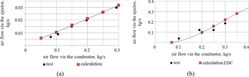
When performing calculations, the velocity constants of chemical reactions are selected for the mechanism of fuel oxidation, which makes it possible to obtain a satisfactory validation of the calculations with experimental data for the given class of fuel-burning devices.
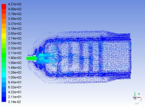
The velocity vectors inside the combustor are shown in . In the combustor’s front device, due to the presence of a special vane swirler, a zone of recirculation flows takes place. This zone is smaller in size compared with a standard gas turbine chamber, because the velocity of off-gas outflow from the nozzle is much higher than the velocity of the outflow of typical gaseous fuel, such as natural gas. Therefore a sufficiently large amount of off-gas does not enter the peripheral sections of the combustion liner, and the burnout process is delayed, while the size of the fuel flame increases.
Figure 7. Velocity vector coloured by velocity magnitude, m s−1.
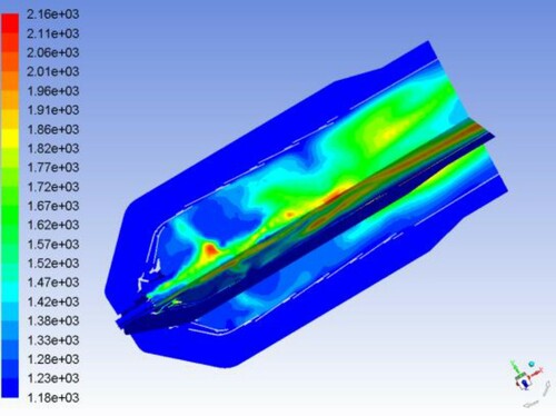
Such an aerodynamic flow structure determines the temperature distribution over the combustor’s sections (). It is seen that, due to a decrease in the central recirculation zone, the combustion process is less stable compared to a traditional combustor operating on liquid fuel or natural gas. The zone of maximum gas temperatures shifts to the secondary air supply holes, although the maximum values do not exceed 2160 K.
Figure 8. Contours of static temperatures, K.
The concentrations of chemical components are shown in . The calculated concentrations of the components at the combustion liner outlet are as follows: CO = 367 ppm, H2 = 12 ppm, NO = 4.4 ppm. The concentrations of carbon monoxide CO are quite high, which is explained by an increase in the flow velocity in the axial regions and a shift in the active reaction zone closer to the exit combustor’s section.
Figure 9. Contours of mass fraction of (a) H2; (b) CO; (c) CO2; (d) NO.
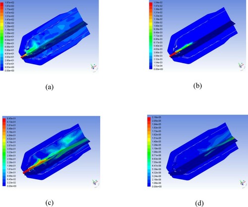
The calculation results show the potential for organising stable combustion of the SOFC off-gas of low heating value in a traditional gas turbine combustor due to the presence of a sufficient amount of hydrogen in the fuel. However, several of the combustors’ characteristics need to be improved by the following modifications: the efficiency of the off-gas combustion (emissions of CO and unburned hydrocarbons), the temperature regime of the combustion liner walls, and dimensions. Note that the above characteristics can be improved, for example, using advanced systems of plasma-chemical combustion activation (Serbin Citation1998; Matveev et al. Citation2007a).
The proposed technology using a hybrid solid oxide fuel cell-gas turbine with over-expansion system provides ample opportunities to improve the efficiency and environmental friendliness of practical ship power systems. This is especially true for satisfying the requirements of the International Maritime Organization (IMO) on the Energy Efficiency Design Index (EEDI) in the design, construction, and operation of different types of ships, which will be significantly enhanced by 2025. The presented technology concerns mainly auxiliary ship power plants. Note that the outlook over approximately half of the world fleet shows that till 2035 a market volume up to 3900 fuel cell units of 500 kW is possible (Vogler and Würsig Citation2010). In this regard, the calculated parameters of the proposed auxiliary hybrid plant with about 520 kW power provide both energy and environmental indicators that satisfy the IMO requirements for newly built vessels. Reducing the optimum pressure in the SOFC-GT cycle will give rise to the production of equipment (fuel cells, reformers, and regenerators) with lighter weight and increased lifetime.
Currently, available SOFC systems are significantly more expensive than conventional ones; however, due to the rapid development of similar technologies in stationary power engineering, their cost can be expected to decrease. Further technical and economic analysis is required to substantiate the economic feasibility of using the proposed hybrid system concerning various possible fuels and specific characteristics of the vessel.
5. Conclusions
In the presented work, we performed a theoretical investigation of the possibilities of using a hybrid SOFC-GT system with a regenerative gas turbine operating with over-expansion in marine engineering. The main results of the work are as follows:
For the first time, to increase the efficiency of the SOFC-GT hybrid cycle, it was proposed to use a gas turbine with over-expansion and special exhauster, which provides expansion in the turbine part to pressure significantly lower than atmospheric. The carried out thermodynamic calculations showed that in this case, it is possible to reduce the pressure in the SOFC stack up to 0.18–0.20 MPa and provide a significant increase in the efficiency and lifetime of the fuel cell stacks.
A mathematical model of the hybrid SOFC-GT system has been developed, which allows the optimisation of the thermodynamic parameters of its gas turbine part.
It has been established that the gas temperature at the turbine inlet in the proposed SOFC-GT scheme is strictly determined by the design parameters of the SOFC stack at the nominal operating mode.
The presence of a turbine with over-expansion also determines an increase in the efficiency of the entire thermal scheme of a hybrid power plant in comparison with the currently available scheme with fuel cells and a regenerative gas turbine engine.
It is shown that the use of a gas turbine engine in the proposed SOFC-GT scheme achieves a total complex efficiency of 55% (at the SOFC operating temperature of 1183 K and its efficiency 46.2%), which corresponds to an increase in the efficiency of electrical power generation by ∼ 19%.
Recommended optimal parameters of the gas turbine as a part of the developed SOFC-GT system are the following: the gas turbine compression ratio is 1.95–2.2 and the exhauster compressor ratio is 1.3–1.4, which determines the range of the gas turbine inlet temperature of 1050–1090 K.
Three-dimensional calculations of the individual UGT2500 gas turbine combustor showed the possibility of efficient use of the SOFC off-gas with a very low heating value as the main fuel, the stability of the burning process, and the minimal NOx emission that do not exceed 5 ppm due to the relatively low maximum temperature level of the process inside the combustion zone.
Acknowledgements
We gratefully acknowledge the financial support of the Ministry of Education and Science of Ukraine (M/107-2019), the Ministry of science and technology of China (CU0310), National Natural Science Foundation of China (51776092), Natural Science Foundation of Jiangsu Province (BK20151325).
Disclosure statement
No potential conflict of interest was reported by the author(s).
Additional information
Funding
References
- Baldi F, Moret S, Tammi K, Marechal F. 2020. The role of solid oxide fuel cells in future ship energy systems. Energy. 194(1):1–22.
- Capstone Turbine Corporation. 2020. https://www.capstoneturbine.com.
- Cheddie DF. 2010. Integration of a solid oxide fuel cell into a 10 MW gas turbine power plant. Energies. 3:754–769. doi:https://doi.org/10.3390/en3040754.
- Chen D, Xu Y, Hu B, Yan C, Lu L. 2018. Investigation of proper external air flow path for tubular fuel cell stacks with an anode support feature. Energy Convers Manage. 171:807–814. doi:https://doi.org/10.1016/j.enconman.2018.06.036.
- Chen D, Xu Y, Tade MO, Shao Z. 2017. General regulation of air flow distribution characteristics within planar solid oxide fuel cell Stacks. ACS Energy Letters. 2:319–326. doi:https://doi.org/10.1021/acsenergylett.6b00548.
- Cherednichenko O, Serbin S. 2018. Analysis of efficiency of the ship propulsion system with thermochemical recuperation of waste heat. J Mar Sci Appl. 17(1):122–130. doi:https://doi.org/10.1007/s11804-018-0012-x.
- Cherednichenko O, Serbin S, Dzida M. 2019. Application of thermo-chemical technologies for conversion of associated gas in diesel-gas turbine installations for oil and gas floating units. Pol Marit Res. 26(103):181–187. doi:https://doi.org/10.2478/pomr-2019-0059.
- Díaz-de-Baldasano MC, Mateos FJ, Núñez-Rivas LR, Leo TJ. 2014. Conceptual design of offshore platform supply vessel based on hybrid diesel generator-fuel cell power plant. Appl Energy. 116:91–100.
- Fernandes A, Brabandt J, Posdziech O, Saadabadi A, Recalde M, Fan L, Promes EO, Liu M, Woudstra T, Aravind PV. 2018. Design, construction, and testing of a gasifier-specific solid oxide fuel cell system. Energies. 11:1–17.
- Fuentes DI, Pérez HL. 2015. Fuel-cell integration on board surface ships. Ship Sci Technol. 8(16):19–28.
- Gatsenko NA, Serbin SI. 1995. Arc plasmatrons for burning fuel in industrial installations. Glass Ceram. 51(11–12):383–386. doi:https://doi.org/10.1007/BF00679821.
- Gimelli A, Sannino R. 2017. Thermodynamic model validation of Capstone C30 micro gs turbine. Energy Procedia. 126(201709):955–962.
- Han J, Charpentier JF, Tang T. 2015. State of the art of fuel cells for ship applications. HAL-01073612. https://hal.archives-ouvertes.fr/hal-01073612, doi:https://doi.org/10.1109/ISIE.2012.6237306.
- Kwaśniewski T, Piwowarski M. 2020. Design analysis of hybrid gas turbine-fuel cell power plant in stationary and marine application. Pol Marit Res. 27(106):107–119. http://www.bg.pg.gda.pl/pmr/pdf/PMRes_2020_2.pdf.
- Langfeldt L. 2018. Maritime fuel cell applications. Technologies and ongoing developments. https://www.jterc.or.jp/koku/koku_semina/pdf/180221_presentation-01.pdf.
- Lemański M, Topolski J, Badur J. 2004. Analysis strategies for gas turbine-solid oxide fuel cell hybrid cycles. In: Domachowski Z, editor. Technical, economic, and environmental aspects of combined cycle power plants. Gdańsk: TU Press; p. 213–220.
- Lingstädt T, Grimm F, Krummrein T, Bücheler S, Aigner M. 2018. Experimental investigation of an SOFC off-gas combustor for hybrid power plant usage with low heating values realised by natural gas addition. In: GPPS Forum 18 Global Power and Propulsion Society, Montreal, 1–8. https://doi.org/https://doi.org/10.5281/zenodo.1342414.
- Matveev I, Matveeva S, Serbin S. 2007a. Design and preliminary result of the plasma assisted Tornado combustor. In: 43rd AIAA/ASME/SAE/ASEE Joint Propulsion Conference, Cincinnati, OH, AIAA 2007-5628.6:6091–6098.
- Matveev I, Serbin S. 2006. Experimental and numerical definition of the reverse vortex combustor parameters. In: 44th AIAA Aerospace Sciences Meeting and Exhibit, Reno, Nevada, AIAA-2006-0551, 6662–6673.
- Matveev I, Serbin S. 2012. Investigation of a reverse-vortex plasma assisted combustion system. In: ASME 2012 Heat Transfer Summer Conf., Puerto Rico, USA, HT2012-58037. 2012:133(140. https://doi.org/https://doi.org/10.1115/HT2012-58037.
- Matveev I, Serbin S, Mostipanenko A. 2007b. Numerical optimization of the “Tornado” combustor aerodynamic parameters. In: 45th AIAA Aerospace Sciences Meeting, Reno, Nevada, AIAA 2007-391.7, 4744–4755.
- Matveev IB, Serbin SI, Vilkul VV, Goncharova NA. 2015. Synthesis gas afterburner based on an injector type plasma-assisted combustion system. IEEE Trans Plasma Sci. 43(12):3974–3978. doi:https://doi.org/10.1109/TPS.2015.2475125.
- McPhail SJ, Leto L, Boigues-Muñoz C. 2012. The Yellow Pages of SOFC Technology, International Status of SOFC Deployment 2012-2013. IEA Implementing Agreement Advanced Fuel Cells, Annex 24 – SOFC, https://www.researchgate.net/publication/311869822_The_Yellow_Pages_of_SOFC_Technology_International_Status_of_SOFC_deployment_2012-2013.
- Minnehan JJ, Pratt JW. 2017. Practical application limits of fuel cells and batteries for zero emission vessels. SANDIA Report: SAND2017-12665.
- National Fuel Cell Research Center. 2010. Hybrid fuel cell / gas turbine systems. Analyses of hybrid fuel cell gas turbine systems. http://www.nfcrc.uci.edu/PDF_Research_Summaries/HYBRIDfuelCELL_GASturbineSystems-AnalysesHybridFuelCellGasTurbineSystems.pdf.
- Nguyen TV, Elmegaard B, Pierobon L, Haglind F, Breuhaus P. 2012. Modelling and analysis of offshore energy systems on North Sea oil and gas platforms. Proceedings of the 53rd SIMS conference on Simulation and Modelling. https://backend.orbit.dtu.dk/ws/portalfiles/portal/38487211/content.pdf.
- Pratt JW, Chan SH. 2017. Maritime fuel cell generator project. SANDIA Report: SAND2017-5751.
- Saisirirat P. 2015. The solid oxide fuel cell (SOFC) and gas turbine (GT) hybrid system numerical model. Energy Procedia. 79:845–850. doi:https://doi.org/10.1016/j.egypro.2015.11.576.
- Sanusi YS, Mokheimer EMA. 2019. Performance analysis of a membrane-based reformer-combustor reactor for hydrogen generation. Int J Energy Res. 43:189–203. doi:https://doi.org/10.1002/er.4250.
- Schumacher E. 2018. Alternative fuels and fuel cells in ships – Status of the e4ships. Project Cluster, NOW GmbH. https://www.altenergy.info/wp-content/uploads/2018/10/2-Erik-Schumacher-e4ships-Project-Cluster.pdf.
- Serbin SI. 1998. Modeling and experimental study of operation process in a gas turbine combustor with a plasma-chemical element. Combust Sci Technol. 139:137–158. doi:https://doi.org/10.1080/00102209808952084.
- Serbin SI. 2006. Features of liquid-fuel plasma-chemical gasification for diesel engines. IEEE Trans Plasma Sci. 34(6):2488–2496. doi:https://doi.org/10.1109/TPS.2006.876422.
- Serbin S, Goncharova N. 2017. Investigations of a gas turbine low-emission combustor operating on the synthesis gas. Int J Chem Eng. 2017:1–14. doi:https://doi.org/10.1155/2017/6146984.
- Serbin SI, Matveev IB, Goncharova NA. 2014. Plasma assisted reforming of natural gas for GTL. Part I. IEEE Trans Plasma Sci. 42(12):3896–3900. doi:https://doi.org/10.1109/TPS.2014.2353042.
- Serbin SI, Matveev IB, Mostipanenko GB. 2011. Investigations of the working process in a “lean-burn” gas turbine combustor with plasma assistance. IEEE Trans Plasma Sci. 39(12):3331–3335. doi:https://doi.org/10.1155/2017/6146984.
- Serbin SI, Washchilenko NV, Cherednichenko OK, Chen D, Zonming Y. 2020. Hybrid power plant on fuel elements. Decision on the issuance of a declaratory patent for invention application 2019 11476 (Ukraine) from November 27, 2019.
- Sun J, Stebe J, Kennell C. 2010. Feasibility and design implications of fuel cell power for sealift ships. Nav Eng J. 122(3):87–102. doi:https://doi.org/10.1111/j.1559-3584.2010.00274.x.
- Tunca F, Kaya N. 2017. Thermodynamic analysis of gas turbine–solid oxide fuel cell (GT-SOFC) aircraft auxiliary power unit (APU). Int J Adv Mech Auto Eng. 4(1):10–14.
- U.S. Dept. of Energy, Office of Fossil Energy. 2004. Fuel Cell Handbook, 7th Edition. National Energy Technology Laboratory, Morgantown, West Virginia: EG&G Technical Services, Inc.
- van Biert L, Godjevac M, Visser K, Aravind PV. 2016. A review of fuel cell systems for maritime applications. J Power Sources. 327:345–364. doi:https://doi.org/10.1016/j.jpowsour.2016.07.007.
- Vogler F, Würsig G. 2010. Fuel cells in maritime applications. Challenges, chances and experience. http://conference.ing.unipi.it/ichs2011/papers/158.pdf.
- Welaya YMA, Ammar NR. 2013. Thermodynamic analysis of a combined gas turbine power plant with a solid oxide fuel cell for marine applications. Int J Naval Architect Ocean Eng. 5(4):529–545. doi:https://doi.org/10.2478/IJNAOE-2013-0151.
- Zaccaria V, Tucker D, Traverso A. 2017. Gas turbine advanced power systems to improve solid oxide fuel cell economic viability. J Global Power Propul Soc. 1:28–40.