
 ?Mathematical formulae have been encoded as MathML and are displayed in this HTML version using MathJax in order to improve their display. Uncheck the box to turn MathJax off. This feature requires Javascript. Click on a formula to zoom.
ABSTRACT
Additive manufacturing has shown giant potential in advanced manufacturing industry. However, distortion of additive-manufactured parts may interrupt the printing process and decrease manufacturing precision, causing a significant waste of time and money. Distortion, a common problem in additive manufacturing, has not been sufficiently researched. In this study, we provide a comprehensive understanding of distortion in additive manufacturing based on assumption of constraining force. A quantitative model was established to illustrate inconsistent shrinkage during the additive process. A qualitative model was then built for showing the distortion caused by inconsistent shrinkage. It can be founded that inconsistent shrinkage accumulated during the additive process drives the final distortion of part. We concluded most influencing factors of distortion together, forming towards a comprehensive understanding of distortion in additive manufacturing. This study not only links micro melting-solidification process and macro structural mechanics in science, but also provides systematic solutions for decreasing the distortion in additive manufacturing for engineering.
1. Introduction
Additive manufacturing is a promising approach for fabricating complex-shaped and high-performance objects without molds (Debroy et al. Citation2019; Yang et al. Citation2020; Morgan et al. Citation2019; Wang et al. Citation2019). It has been utilised in producing newly-designed lightweight and integrated structures for aerospace, medical, and automotive applications (Sing and Yeong Citation2020; John and Mohsen Citation2016), and has become an area of intense research focus in science and industry (Romero, Yang, and Bolzoni Citation2018; Yang et al. Citation2021).
Distortion is the deviation of an additive-manufactured part from its designed shape or dimensions (Anandan and Kumaraguru Citation2019). It is a common problem in additive manufacturing, such as selective laser melting (SLM or LPBF (Laser powder bed fusion, ISO/ASTM 52900-15)), laser melting deposition (LMD or LDED (Laser directed energy deposition)), fused deposition molding (FDM or ME (material extrusion)), stereolithography (SLA or VP (vat photoploymerization)), and digital light processing (DLP). For instance, a cantilever structure built by SLM bends upwards after being cut from the substrate (C. Li et al. Citation2017). The shape deviations of a part may interrupt the additive process by hindering the movement of the roller, causing a significant waste of time and money. Distortion also decreases the precision of the built part, which may cause it to be rejected for use in critical applications.
Previous studies have explored the mechanism of distortion. Kruth et al. Citation2012 explained the micro-process of metal additive manufacturing on the basis of the thermal gradient mechanism (TGM), which fit quite well with the experimental results of in-time distortion measurement from (Denlinger, Heigel, and Michaleris Citation2015; Denlinger et al. Citation2017) and (Biegler, Graf, and Rethmeier Citation2018). TGM provides micro and qualitative insights into mechanism of distortion. It helps to understand the distortion of simple structure fabricated by simple scan strategy. However, it cannot be used to detailedly explain the influences of structure, material property and scan strategy on the distortion from a macro perspective. The gap between the micro melting-solidification process and the macro distortion still exists.
Many efforts have been made to explore the influencing factors and regularity of distortion. Researchers have attempted to predict the distortion of additive-manufactured parts by numerical simulation (Prabhakar et al. Citation2015; Tawfik, Nasr, and Gamal Citation2019; Y. Li et al. Citation2017). Zielinski et al. Citation2017 investigated the distortion evolution of a bridge-geometry part, and revealed significant changes in distortion once the two piers of the bridge connected. Afazov et al. Citation2017 and Seidel and Zaeh Citation2018 simulated the distortion of a blade, and proposed approaches to decrease the distortion by pre-compensation of the blade. Zhang and Zhang Citation2017 studied the distortion of a bar with several channels via finite element analysis, and found that a thick and low-density porous layer could reduce residual stress and distortion. Li (Li et al. Citation2016; C. Li et al. Citation2017) investigated the influence of scan patterns on the distortion via simulation and experiments, and found that vertical scanning results in less distortion than horizontal scanning. Williams, Davies, and Hooper Citation2018 found that the distortions are almost the same when the same volume of metal is deposited, and it is not necessary to model every laser pass or even every deposited layer to accurately predict the final distortion. Tan et al. Citation2019 pointed out that solid-state phase transformation should be considered in thermo-metallurgical-mechanical coupling model for selective laser melting. Pre-heating the powder bed and the substrate is regarded as an effective method to decrease the distortion (Zaeh and Brannen Citation2010; Vilaro, Colin, and Bartovt Citation2011; Buchbinder et al. Citation2014). Denlinger et al. Citation2015 found out that adding dwelling time between layers is beneficial for reducing the distortion. Kruth et al. Citation2012 stated that post-heat treatment can decrease the maximum distortion to 20%. Nickel, Barnett, and Prinz Citation2001 and Gao et al. Citation2013 validated that the scan patterns have a critical impact on distortion. Although studies have shown some influencing factors of distortion by means of numerical simulation and experiments, people may still have to try several times to achieve a successful print. An overall image of distortion is required to be depicted.
The present authors have recently developed a new assumption for discussing distortion in metal additive manufacturing (Xie et al. Citation2018). A pair of constraining forces was assumed at the interface between the newly added layer and previous added layer or substrate. The distortion was regarded as a result of one constraining force acting on the built structure. The assumption of constraining force provides a macro perspective for the discussion of distortion in additive manufacturing. The aim of the present study was to link the micro melting-solidification process and the macro distortion behaviour, as well as to integrate most influencing factors together.
2. Methodology
2.1. Selective laser melting
The experiments were conducted with a laboratory-assembled SLM machine equipped with a 200-W fibre laser (IPG Co. Ltd., USA), a scanner (Scanlab Co. Ltd., Germany), and an AMCP controller (Materialise Co. Ltd., Belgium). The austenitic stainless steel AISI 316L (Maite Powder Co. Ltd, China) was chosen. The optimised processing parameters of SLM were laser power 180 W, scanning speed 1 m/s, hatch distance 50 μm, layer thickness 30 μm. The scan directions were always parallel to the longitudinal direction of the arm. The built cantilever structures were then cut from the substrate by wire electrical discharge machining (WEDM). The longitudinal section was cut by WEDM and then etched with CuSO4 (10 g) + HCl (50 ml) + H2O (50 ml). The displacement of points along the central line on the top surface of each arm were measured by a coordinate measuring machine (Leader Metrology Co. Ltd., USA).
2.2. Selective laser sintering
SLS experiments were completed with a commercial SLS machine (P760, EOS Co. Ltd., Germany) equipped with two 50-W CO2 lasers. The nylon PA12 (EOS Co. Ltd., Germany) was chosen as the raw material. The material was heated to 145 °C for 1 h before laser sintering. The optimised processing parameters of SLS were laser power 15 W, scanning speed 1.2 m/s, hatch distance 50 μm, layer thickness 100 μm. The laser scan direction was set parallel to the longitudinal direction of the arm. The distortion was characterised by a coordinate measuring machine (CMM; Leader Metrology Co. Ltd., USA).
2.3. Fused deposition molding
FDM experiments were conducted on a commercial FDM machine (Guider II, Flashforge Co. Ltd., China). A 1.75 mm-diameter polylactic acid wire was used as material. The processing parameters were base temperature 80 °C, heating temperature 220 °C, scan speed 30 mm/s, layer thickness 0.1 mm.
2.4. Stereolithography
SLA experiments were conducted on a commercial SLA machine (SPS350B, Hengtong Co. Ltd., China) with the following processing parameters: laser power 220 mW, scanning speed 8 m/s, hatch distance 50 μm, layer thickness 100 μm. The laser scan direction was always parallel to the longitudinal direction of the arm. The liquid resin SPR6000 epoxy (Hengtong Co. Ltd., China) was cured by ultraviolet light at a wavelength of 355 nm. The distortion was characterised by CMM (Leader Metrology Co. Ltd., USA).
2.5. Digital light processing
DLP experiments were conducted on a commercial DLP machine (Prismlab Co. Ltd., China) with the following processing parameters: exposure intensity 50 mJ/cm2, exposure time 3 s, layer thickness 0.1 mm. The liquid resin P400 (Prismlab Co. Ltd., China) was used as the raw material.
3. Results
3.1. Distortion in additive manufacturing
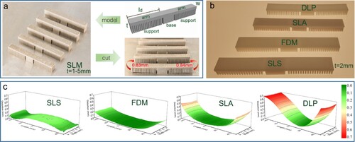
A typical cantilever structure was designed as shown in a. Cantilever structures of various arm thicknesses were fabricated by SLM. After the arms were cut from the substrate, the arms bent upwards. The distortion can be also found in parts built by other additive manufacturing techniques, including SLS, FDM, SLA, and DLP. The distortion in additive manufacturing reduced the precision of these parts.
Figure 1. Distortion of cantilever structures in additive manufacturing. a Distortion of a cantilever structure built by SLM. b Cantilever structures (arm thickness t = 2 mm) built by SLS, FDM, SLA, and DLP. c Distortion of cantilever structures (arm thickness t = 2 mm) built by SLS, FDM, SLA, and DLP measured by a coordinate measuring machine.
3.2. Inconsistent shrinkage during the additive process
In this study, SLM was the main focus because it enables noticeable distortion of cantilever structures after they are cut from the substrate (Cheng et al. Citation2019). In order to ensure the manufacturability of the arms, a sacrificial support is required because it can provide mechanical fixture and a heat dissipation channel (Cheng et al. Citation2019). Austenitic stainless steel (AISI 316L) was chosen as the research material.
Unlike the micro mechanism of TGM, the assumption of constraining force offers a method to recognise the distortion mechanism in additive manufacturing from a macro view (Xie et al. Citation2018). Each layer of the deposited arm was regarded as uniform and underwent the same melting-solidification process in SLM. The laser scan direction was always along the longitudinal direction of the arm. In a, a schematic of one layer of a cantilever arm is shown at high temperature (HT). When cooled to low temperature (LT), the free end of the deposition layer shrinks with a shrinkage length of u0 if there is no constraint, as shown in b. However, the sacrificial support also constrains the shrinkage of the deposited arm at the same time. Hence, the shrinkage of the first layer can be set as rather than u0. The constraining forces
can be assumed at the interface between the deposited first layer and the support, as shown in c. Similarly, the constraining forces
can be assumed at the interface between the layer i and the layer i-1, as shown in d. The shrinkage of layer i is set as
.
Figure 2. Assumption of constraining force and experimental validation. a Deposited arm at HT without support. b Deposited arm at LT without support. Its shrinkage is u0. c Assumption of constraining force between the support and the first layer. d Assumption of constraining force between layer i − 1 and layer i. e The bent support predicted by the assumption of constraining force. f The experimental bent support.
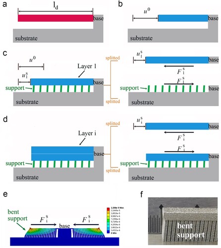
We used a model to predict what will happen if we set constraining force on the cantilever structure. The arm length is 20 mm, while the arm width is 6 mm. The arm thickness is 0.3 mm, which means 10 layers of metal. As shown in e, we set 1000 N as an initial value for the constraining force (i = 10) in mechanical finite element analysis tools Workbench (ANSYS Ltd., USA). The bottom of support and top surface of substrate is set to be fixed. It can be found that the support can be bent towards the base. The experimental results validated that the support structure was bent towards the base, as shown in f.
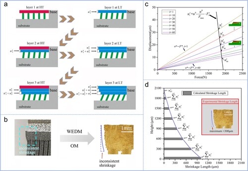
As shown in a, the shrinkage of layer 1 from HT to LT is . Then, layer 2 at HT is deposited on layer 1. When layer 2 cools to LT, the shrinkage of layer 2 is
.
is a balanced result of the shrinkage of layer 2 and the constraint of layer 1 together with the support structure. The shrinkage of layer 1 becomes
after layer 2 cools. Similarly, the shrinkage of layer 1 is
after layer 3 cools, and the shrinkage of layer 2 become
. Each new added layer shrinks, causing the support and the previous deposition layers to contract towards the fixed end. With the increase in deposition height, the inconsistent shrinkage of the deposited layers emerges. It can be predicted that the temporary shrinkage
of layer i decreases with the increase in deposition height because the previous deposited structure with greater height has greater shear stiffness. Thus, the increment of shrinkage becomes less when the deposited height increases, as shown in b.
Figure 3. Evolution of inconsistent shrinkage during the additive manufacturing process. a Accumulation of shrinkage during the additive process. b Experimental inconsistent shrinkage. c Calculated shrinkage of each layer under the assumption of constraining force. d Comparison of calculated and experimental inconsistent shrinkage of the part (t = 2 mm).
From the schematic in d, the assumption of constraining force makes it possible to calculate the temporary shrinkage of layer i. On one hand, the constraining force
causes the previous structure, i.e. the support and layer i-1 deposition, to contract. According to finite element analysis, a certain shrinkage u* can be obtained if forces F* are applied to the arms of the cantilever structure with i-1 layers’ deposition. The Young's modulus is reported as 193 GPa (Yakout, Elbestawi, and Veldhuis Citation2019). A relationship between u* and F* can be fitted and then depicted, as shown in c. There will be N curves if the maximum number of deposition layers is N. In c, several curves concerning u* and F* are shown when the deposition number of layers varies from 1 to 60. For example, the red dotted line in c reflects the changes of u* when the forces F* with different values act on the arm with nine layers.
On the other hand, the deposited layer i shown in d is regarded as an elastic rod. The shrinkage of layer i should satisfy Hooke's law:
(1)
(1)
(2)
(2) Here,
is the assumed the constraining force at the interface between layer i and layer i-1, as shown in d. Fmax can be calculated as (Xie et al. Citation2018)
(3)
(3) Ed and Ad are the Young's modulus and cross-sectional area of the deposition at room temperature, respectively. αd is the mean thermal expansion coefficient of the deposition, and ΔT represents the temperature differences between solidus temperature and temperature of substrate or previous deposition. βpt is the shrinkage rate caused by phase transformation. The values of αd, ΔT, and βpt are 20.02×10⁻⁶/°C, (1371 − 20) °C, and 2.78×10⁻², respectively (Xie et al. Citation2018). In this experiment, the arm width w was 6 mm. The thickness of each layer was 30 μm. Thus, the value of Fmax can be calculated as
(4)
(4) The length of the arm was 20 mm; the maximum shrinkage u0 can be calculated as
(5)
(5) By applying Equation (2) to c, the shrinkage of
can be obtained. Thus, the final shrinkage of each layer can be calculated, as shown in d. The designed height of the arm was 2 mm. Thus, there should be 67 layers in total when the thickness of each layer is 30 μm. The shrinkage of the top layer is
, whereas the shrinkage of the bottom layer is the summation
. The connection of each layer's calculated shrinkage denotes the end of the arm. The experimental shrinkage lengths agree closely with the calculated shrinkage lengths. They share almost the same tendency from top to bottom. The differences between the calculated and experimental maximum shrinkage lengths may due to the anisotropy of the microstructure, changes in local properties caused by thermal elastoplastic behaviour, the contraction in the deposition direction, and the imprecise estimation of shrinkage caused by thermal variation and phase transformation. It is reported that the accumulated heat can maintain the previous deposited structure at 500–1200 K (Luo and Zhao Citation2019). The constraining force can be distinctly decreased with ΔT, which means the difference between the solidus temperature and the previous deposition's temperature. Although accurate calculation of the constraining force requires further study, the idea of constraining force is critical to quantitatively recognising the shrinkage of the deposited structure layer by layer. In this study, it revealed the evolution of inconsistent shrinkage of the cantilever structures during the additive manufacturing process.
3.3. Distortion caused by inconsistent shrinkage after cutting
Distortion of cantilever structures is reported to occur after the arm is cut from the support and substrate (Anandan and Kumaraguru Citation2019; Li et al. Citation2016). However, the distortion mechanism has not been clarified. In this paper, we propose a distortion mechanism concerning the relationship between distortion and inconsistent shrinkage, as shown in a and b. Rod A and rod B are regarded as ideal elastic bodies with the same original lengths in free state. First, they are stretched by forces FA and FB, respectively. Then, the two rods are tightly connected, such as by welding, which is similar to the connection between two layers in SLM and other additive manufacturing processes. As shown in a, if the forces FA and FB are equal in value, the two rods will contract to the original state with no distortion after the forces are removed. However, as shown in b, if FA is greater than FB, the movement of the two rods will be composed of shrinkage and distortion after the removal of the two forces. There will be compressive strain in rod A and tensile strain in rod B, resulting in strain equilibrium at the interfaces between the two rods. The difference in length between rod A and B is thought to offer the strain energy of distortion. It can also be deduced that a greater difference between FA and FB results in greater distortion of rods A and B.
Figure 4. Distortion caused by inconsistent shrinkage. a Consistent shrinkage causes no distortion. b Inconsistent shrinkage drives the distortion. c Edges of SLM parts with various arm thicknesses, showing the inconsistent shrinkage of these parts. d Comparison of the edges (inconsistent shrinkage) of SLM parts (t=1 mm and t=5 mm) when the arm thicknesses are the same. e Inconsistent shrinkage of various arm thicknesses built by SLM causes various distortions. f Distortion of FDM parts with various arm thicknesses. The arm length is 30 mm, and the arm width is 15 mm. g The distortions change with arm thicknesses built by SLA, FDM, DLP, and SLS.
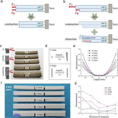
The inconsistent shrinkage of the 67-layer deposition is shown in d. The shrinkage of each layer is less than the maximum shrinkage u0; thus, each layer further contracts when the arm is cut from the substrate. By combining d and b, the 67 layers as built with different shrinkage lengths can be regarded to be stretched by 67 different forces, which are in accordance with the assumed 67 constraining forces. The distortion emerges after the arm is cut from the substrate, which means that the 67 forces are set to be free. In a word, the inconsistent arm shrinkage caused by the different shrinkage of each deposition offers the strain energy of distortion after the arm is cut from the substrate.
The relationship between the inconsistent shrinkage and distortion of part will be illustrated as follows. c demonstrates the edges of SLM parts with various arm thicknesses, which show the inconsistent shrinkage of these parts. If we want to compare the distortion caused by different inconsistent shrinkage, we should let the arm thicknesses (i. e., volume of arm) be the same. As shown in d, we magnify the edge (i. e., inconsistent shrinkage) of part with 1-mm thickness to 5 times. It can be found that the inconsistent shrinkage of part with 1-mm thickness is much bigger than that of part with 5-mm thickness. It can be deduced that the distortion of part with 1-mm thickness is bigger than that of part with 5-mm thickness, which can be validated in (e). The result is also consistent with those in the literature (Anandan and Kumaraguru Citation2019; Li et al. Citation2016; Buchbinder et al. Citation2014). The same tendency can also be found in parts built by FDM, SLA, and DLP, as described in g. However, the distortion of SLS parts does not change distinctly because of the high-temperature preheating process in SLS.
4. Discussions
4.1. The mechanism of distortion in selective laser melting
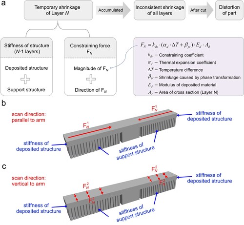
It can be found that the shrinkage of each layer and inconsistent shrinkage of all layers can be calculated based on the assumption of constraining force, as shown in and 3. The link between the inconsistent shrinkage and distortion of part is illustrated in . Thus, we are able to illustrate the mechanism of distortion and its overall influencing factors, as shown in a. Firstly, there is temporary shrinkage of each layer. As the additive process progresses, the temporary shrinkage accumulates, causing inconsistent shrinkage of all layers. After the built part is cut from the substrate, the inconsistent shrinkage drives the part to distort. Thus, the temporary shrinkage, especially in the first few layers, should be decreased so as to decrease the inconsistent shrinkage from top layer to bottom layer and the final distortion of built part. The temporary shrinkage of layer N is determined by the stiffness of the structure and constraining force FN. The structure is composed of deposited structures (N − 1 layers) and support structure. The constraining force is a vector with magnitude and direction.
Figure 5. Mechanism of distortion. a Mechanism of distortion and its influencing factors. b physical model for calculating temporary shrinkage when scan direction is parallel to arm. c physical model for calculating temporary shrinkage when scan direction is vertical to arm.
4.2. Application of the distortion mechanism in additive manufacturing
Although different processes can generate different distortion, the distortion mechanism can also be applied in most additive manufacturing techniques. For example, Huang and Jiang Citation2003 said that short raster scanning produces less distortion than long raster scanning in SLA. It can be explained by using (b-c). The long raster scanning (as shown in b) generate more shrinkage because of its relative lower stiffness of deposited structure. Liu et al. Citation2015 studied the influence of layer thickness, nozzle temperature, and scan strategy on the distortion built by FDM. It is said that ‘with the decreasing of layer thickness, the distortion of PLA thin-plate part increases obviously.’ It can be comprehended that the less layer thickness, the less stiffness of deposited structure in the first several layers. The shrinkage in the first several layers is larger when using less layer thickness, causing a bigger distortion of part. It is also said that ‘the low nozzle temperature is helpful to reduce the distortion.’ Lower nozzle temperature means a less temperature difference between nozzle and environment or room. So the distortion can be decreased by lowering the nozzle temperature. Wu et al. Citation2019 stated that the distortion of a DLP printed object depends on the gradient of addition DoC (degree of conversion) in the material and stiffness of structure. The conclusions are consistent with the mechanism shown in (a). Different degree of conversion means different shrinkage of material and different distortion of part. And stiffness of structure is an important factor in distortion of part built by additive manufacturing, which is also emphasised in a.
According to engineering experience, the distortion in SLS is much less, because the pre-heating temperature is quite close to the glass-transition temperature of the sintered material (Zeng et al. Citation2019). So the shrinkage of SLS material is quite small, which means a small distortion of part. As a result, the distortion mechanism shown in can be applied in most additive manufacturing processes including SLM, SLS, SLA, FDM, and DLP.
In addition, many researchers have used the cantilever structure to study the distortion, because the distortion of cantilever structure is more obvious and easy to be measured (Buchbinder et al. Citation2014; Li et al. Citation2015; Li et al. Citation2016; Mugwagwa et al. Citation2018.). In fact, the distortion mechanism can also be applied in other models. For example, Wu et al. Citation2014 depicted the distortion of prism structure built by SLM. Both the horizontal specimen and vertical specimen generate the distortion with edges ‘peeling up’ away from substrate. The authors attributed this behaviour to constraint against in-plane shrinkage imposed by sub-surface layers. The idea is in good consistent with the proposed distortion mechanism in this study. And we can use constraining force models to clearly illustrate the distortion in both horizontal specimen and vertical specimen. Because of the island scan strategy, the integrated constraining forces on the deposition plane (x-y plane) point to the centroid of figure. So the distortion of both horizontal prism and vertical prism can be easily understood. Khouzani et al. Citation2017 studied the distortion of disk-shaped part built by SLM. The built disk was distorted as a ‘dish’ after removal of the substrate and support structure. The scan direction was rotated by 67° between the consecutive layers, so after many layers the integrated constraining forces are centrosymmetric with directions pointed to the centroid (centre of a circle). So the distortion of ‘disk to dish’ can be easily comprehended based on the distortion mechanism shown in .
4.3. Approaches for decreasing the distortion
Based on the a, the approaches to decrease the inconsistent shrinkage and distortion are summarised as follows.
(1) Enhance the stiffness of the structure.
The stiffness of the deposited structure can be enhanced by model optimisation based on morphology and dimension. Furthermore, a part's laying angle in the additive process enables variation in the deposited structure's stiffness, because it can change the slice of the model and the relevant structural stiffness layer-by-layer.
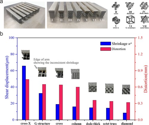
The stiffness of the support structure is believed to have a significant influence on the distortion. We compared seven support structural patterns to validate the link between distortion and the shear stiffness of the support, as shown in . The shear stiffness of a cantilever structure with various support structures is partially calculated in the same way as shown in e. The shrinkage u* was for F* = 1000 N and a deposited arm height of 0.3 mm. As shown in b, the cross-X support offers the smallest shear stiffness, whereas the diamond support affords the largest. The inconsistent shrinkage (shown by the ends of the arms) and the distortion of built parts present the same tendency. Therefore, a higher shear stiffness of support structure can reduce the inconsistent shrinkage and the distortion of built part.
Figure 6. Influence of support structural stiffness on distortion. a The seven designed support–structure patterns. b The relationship between experimental distortion and support structural stiffness (showing by shear displacement in ABAQUS structural mechanics finite element analysis).
(2) Decrease the value of the constraining force.
As shown in a, the value of the constraining force is determined by the constraining coefficient kds, temperature differences ΔT, cross-sectional area Ad, and properties of the built materials, including mean thermal expansion coefficient αd, shrinkage caused by phase transformation βpt, and Young's modulus Ed.
The constraining coefficient kds is believed to be closely related to the micro mechanism i. e., classical thermal gradient mechanism (TGM), as illustrated in (Kruth et al. Citation2012). According to TGM, the molten pool expanded when it is heated and expanded, which has a compressive stress on the surrounding material. After it cools down and shrinks, the solidified molten pool will generate a tensile stress with the surrounding material. We believe that the kds is mainly influenced by the micro process of ‘expansion to shrinkage’. In other words, the kds may be related to the dimension and energy distribution of heat source, the heating time heat source (speed of heat source), the cooling time (the temperature gradient of heat source), the thermal physical properties of the material, and the cooling condition of the surrounding material. For example, we can conclude from engineering experience that the part built by laser may generate less distortion than that built by arc, because laser has a sharper temperature gradient. The material can be heated and cooled more rapidly, causing a less constraining coefficient kds and distortion of part.
The temperature differences ΔT can be decreased by improving the pre-heating temperature, especially when printing the first several layers. The structure of first several layers is prone to shrinkage due to its weak shear stiffness. Studies (Buchbinder et al. Citation2014; Zaeh and Brannen Citation2010; Vilaro, Colin, and Bartovt Citation2011) showed that pre-heating the powder bed and substrate can effectively decrease the final distortion of the cantilever structure. The parts built by SLS show little distortion, as shown in d. This result is attributed to the pre-heating process and the material properties. The pre-heating temperature in SLS is quite close to the glass-transition temperature of the sintered material (Zeng et al. Citation2019). The temperature difference ΔT is decreased dramatically. Furthermore, there is no phase transformation in the cooling process of nylon. The shrinkage tendency illustrated in Equation (3) is quite low. The inconsistent shrinkage during the additive process and the final distortion of the built part can be small. Thus, improving the pre-heating temperature close to the solidus temperature is effective for decreasing distortion of parts built by additive manufacturing techniques involving heating–cooling process, such as SLM, LMD and FDM.
Proper processing parameters, such as heat input, are necessary to reduce distortion. Excessive heat input is believed to increase the constraining coefficient and the corresponding distortion. Materials with lower thermal expansion coefficients, such as Invar 36, exhibit less distortion than those with high thermal expansion coefficients (Yakout et al. Citation2020). Further study is suggested on decreasing the thermal expansion coefficient of metal and thermoplastic polymer, the shrinkage ratio of curing resin, and phase transformation shrinkage of most printing materials. It would be great that the expansive phase transformation during cooling or curing process can be developed for the printing materials.
(3) Optimise the scan strategy.
The direction of constraining force is mainly parallel to the laser scan direction. The inconsistent shrinkage can be decreased by optimising the constraining force direction, which is determined directly by the laser scan direction. Different scan strategies can change the directions and working areas of constraining forces, and thus can change the shrinkage and final distortion of the part. As shown in b and c, different scan direction means different magnitude and direction of constraining force, thus can cause different temporary shrinkage. The rational laser scan strategy (Yang et al. Citation2019; Li et al. Citation2015), fractal scan strategy (Gao et al. Citation2013; Dai and Shaw Citation2002), and island scan strategy (Yan et al. Citation2018) for a certain structure can effectively decrease distortion. It is reported that the distortion can be decreased by almost 50% if the scan vectors was reduced from 20 mm to 2.5 mm (Salem et al. Citation2020). Novel scan strategies are required for structures with different characteristics, under the guidance of . Good scan strategies for decreasing the distortion in SLM can be shared with other techniques including SLA, FDM, and LMD. The island scan strategy can be referred by the optimisation of exposure sequence in DLP.
Besides, the deflection compensation is also an effective way to decrease the distortion of part. The deflection compensation means that the FEA predicted displacements or optical 3D scanned displacements were inverted in the opposite direction, changing the sizes of designed model (Afazov et al. Citation2017). The optical 3D scanned displacements is more reliable for deflection compensation. However, it costs more time and money.
(4) Balance the part quality and distortion
The part built by additive manufacturing (especially SLM or LPBF) is required to have good quality and precision. The priority of distortion is suggested to be higher than that of part quality, because the part quality can be improved by parameters optimisation and post processing including re-melting, polishing, and Hot Isostatic Pressing (HIP). However, the distortion is mainly determined by the factors in additive manufacturing process including part's laying angle, support structure, pre-heating, scan strategy. If given a designed model and required material, the followings factors are suggested to be determined in order: part's laying angle, support structure, pre-heating, scan strategy, parameters optimisation, and post processing. The influence of part's laying angle, support structure, pre-heating, and scan strategy on the distortion have been discussed before. There will be much work on parameters optimisation mainly for improving the density of part, for example laser profile optimisation (Huang et al. Citation2021) and parameter development (Kuo et al. Citation2020). The re-melting is beneficial for improving the density of part (Yu et al. Citation2019). However, it may have complicated impact on part's distortion. In one hand, the higher relative density may lead to a high distortion of part (Mugwagwa et al. Citation2018). In the other hand, the re-melting may function as a pre-heating method, which can decrease the temperature difference and distortion of part. Polishing (Zhang, Chaudhari, and Wang Citation2019) can improve the surface roughness, which may have little effect on density and distortion. HIP (Schneller et al. Citation2019) can effectively improve the relative density of part, however it may also increase the distortion according to (Mugwagwa et al. Citation2018).
5. Conclusions
The influencing factors of distortion in additive manufacturing haven't been systematically researched. In this study, the macro mechanism and influencing factors of distortion have been comprehensively discussed. We established a quantitative model for illustrating inconsistent shrinkage during the additive process. This model links the micro heating–cooling process and the macro structural mechanics. We also developed a qualitative model for showing the distortion caused by inconsistent shrinkage.
It can be concluded that the shrinkage tendency of additive deposition is the intrinsic reason of the final distortion of built parts. Each layer has different temporary shrinkage because of the different shear stiffness of previously deposited structure and support structure. The inconsistent shrinkage, which is the accumulation of all layers’ temporary shrinkage, drives the disengaged part to distort. We also discussed approaches for decreasing the distortion of cantilever structures from the perspective of structural, material, and processing. This study offers a comprehensive understanding of part distortion in most additive manufacturing techniques for scientific research and industrial application.
Acknowledgement
This work was supported by the National Key Research and Development Program ‘Additive Manufacturing and Laser Manufacturing’ (Nos. 2018YFB1105400 and 2018YFB1105801), the National Natural Science Foundation of China (No. 51475238), the Key Research and Development Program of Jiangsu Provincial Department of Science and Technology of China (No. BE2019002), and the China Post Doctoral Fund (No. 2020M671475).
Disclosure statement
No potential conflict of interest was reported by the author(s).
Additional information
Funding
Notes on contributors
Deqiao Xie
Deqiao Xie is a post doctor at Nanjing University of Aeronautics and Astronautics.
Fei Lv
Fei Lv is a graduate student at Nanjing University of Aeronautics and Astronautics.
Huixin Liang
Huixin Liang is a post doctor at Drum Tower Hospital affiliated to Medical School of Nanjing University.
Lida Shen
Lida Shen, Zongjun Tian, Jianfeng Zhao, and Yingdong Song are professors at Nanjing University of Aeronautics and Astronautics.
Zongjun Tian
Lida Shen, Zongjun Tian, Jianfeng Zhao, and Yingdong Song are professors at Nanjing University of Aeronautics and Astronautics.
Jianfeng Zhao
Lida Shen, Zongjun Tian, Jianfeng Zhao, and Yingdong Song are professors at Nanjing University of Aeronautics and Astronautics.
Yingdong Song
Lida Shen, Zongjun Tian, Jianfeng Zhao, and Yingdong Song are professors at Nanjing University of Aeronautics and Astronautics.
Cijun Shuai
Cijun Shuai is a professor at Central South University.
References
- Afazov, S., W. A. D. Denmark, B. L. Toralles, A. Holloway, and A. Yaghi. 2017. “Distortion Prediction and Compensation in Selective Laser Melting.” Additive Manufacturing 17: 15–22.
- Anandan, H., and S. Kumaraguru. 2019. “Distortion in Metal Additive Manufactured Parts.” In 3D Printing and Additive Manufacturing Technologies, edited by L. J. Kumar, P. M. Pandey, and D. I. Wimpenny 281–295. Singapore: Springer. https://www.onacademic.com/detail/journal_1000040808504110_c42d.html
- Biegler, M., B. Graf, and M. Rethmeier. 2018. “In-situ Distortions in LMD Additive Manufacturing Walls Can be Measured with Digital Image Correlation and Predicted Using Numerical Simulations.” Additive Manufacturing 20: 101–110.
- Buchbinder, D., W. Melners, N. Plrch, K. Wissenbach, and J. Schrage. 2014. “Investigation on Reducing Distortion by pre-Heating During Manufacture of Aluminum Parts Using Selective Laser Melting.” J. Laser. Appl 26: 1–10.
- Cheng, L., X. Liang, J. Bai, Q. Chen, J. Lemon, and A. To. 2019. “On Utilizing Topology Optimization to Design Support Structure to Prevent Residual Stress Induced Build Failure in Laser Powder bed Metal Additive Manufacturing.” Additive Manufacturing 27: 290–304.
- Dai, K., and L. Shaw. 2002. “Distortion Minimization of Laser-Processed Components Through Control of Laser Scanning Patterns.” Rapid Prototyping Journal 8: 270–276.
- Debroy, T., T. Mukherjee, J. O. Milewski, J. W. Elmer, and W. Zhang. 2019. “Scientific, Technological and Economic Issues in Metal Printing and Their Solutions.” Nature Materials 18 (10): 1.
- Denlinger, E. R., M. Gouge, J. Irwin, and P. Michaleris. 2017. “Thermomechanical Model Development and in Situ Experimental Validation of the Laser Powder-Bed Fusion Process.” Additive Manufacturing 16: 73–80.
- Denlinger, E. R., J. C. Heigel, and P. Michaleris. 2015. “Residual Stress and Distortion Modeling of Electron Beam Direct Manufacturing Ti-6Al-4V.” Proceedings of the Institution of Mechanical Engineers- Part B: Journal of Engineering Manufacture 229: 1803–1813.
- Denlinger, E. R., J. C. Heigel, P. Michaleris, and T. A. Palmer. 2015. “Effect of Inter-Layer Dwell Time on Distortion and Residual Stress in Additive Manufacturing of Titanium and Nickel Alloys.” Journal of Materials Processing Technology 215: 123–131.
- Gao, M., Z. Wang, X. Li, and X. Zeng. 2013. “The Effect of Deposition Patterns on the Deformation of Substrates During Direct Laser Fabrication.” ASME. J. Eng. Mater. Technol 135: 034502–034506.
- Huang, Y. M., and C. P. Jiang. 2003. “Curl Distortion Analysis During Photopolymerisation of Stereolithography Using Dynamic Finite Element Method.” Int. J. Adv. Manuf. Technol 21: 586–595.
- Huang, S., R. L. Narayan, J. H. K. Tan, S. L. Sing, and W. Y. Yeong. 2021. “Resolving the Porosity-Unmelted Inclusion Dilemma During in-Situ Alloying of Ti34Nb via Laser Powder Bed Fusion.” Acta Materialia 204: 116522.
- John, J., and S. Mohsen. 2016. “Metal Additive Manufacturing: A Review of Mechanical Properties.” Annual Review of Materials Research 46 (1): 151–186.
- Khouzani, M. G., H. Peng, R. Rogge, R. Attardo, P. Ostiguy, J. Neidig, R. Billo, D. Hoelzle, and M. R. Shankar. 2017. “Experimental Measurement of Residual Stress and Distortion in Additively Manufactured Stainless Steel Components with Various Dimensions.” Materials Science & Engineering A 707: 689–700.
- Kruth, J., J. Deckers, E. Yasa, and R. Wauth. 2012. “Assessing and Comparing Influencing Factors of Residual Stresses in Selective Laser Melting Using a Novel Analysis Method.” Proc. Inst. Mech. Eng. Pt. B: J. Eng. Manuf 226: 980–991.
- Kuo, C. N., C. K. Chua, P. C. Peng, Y. W. Chen, S. L. Sing, S. Huang, and Y. L. Su. 2020. “Microstructure Evolution and Mechanical Property Response via 3D Printing Parameter Development of Al–Sc Alloy.” Virtual and Physical Prototyping 15 (1): 120–129.
- Li, C., C. H. Fu, Y. B. Guo, and F. Z. Fang. 2015. “Fast Prediction and Validation of Part Distortion in Selective Laser Melting.” Procedia Manufacturing 1: 355–365.
- Li, C., C. H. Fu, Y. B. Guo, and F. Z. Fang. 2016. “A Multiscale Modeling Approach for Fast Prediction of Part Distortion in Selective Laser Melting.” Journal of Materials Processing Technology 229: 703–712.
- Li, C., J. F. Liu, X. Y. Fang, and Y. B. Guo. 2017. “Efficient Predictive Model of Part Distortion and Residual Stress in Selective Laser Melting.” Additive Manufacturing 17: 157–168.
- Li, Y., K. Zhou, P. Tan, B. T. Shu, and K. F. Leong. 2017. “Modeling Temperature and Residual Stress Fields in Selective Laser Melting.” International Journal of Mechanical Sciences 136: 24–35.
- Liu, X., S. Li, Z. Liu, X. Zheng, X. Chen, and Z. Wang. 2015. “An Investigation on Distortion of PLA Thin-Plate Part in the FDM Process.” Int. J. Adv. Manuf. Technol 79: 1117–1126.
- Luo, Z., and Y. Zhao. 2019. “Numerical Simulation of Part-Level Temperature Fields During Selective Laser Melting of Stainless Steel 316L.” The International Journal of Advanced Manufacturing Technology 104: 1615–1635.
- Morgan, L., L. Sophie, D. Amy, H. Azad, G. Paola, C. Luke, E. Neil, G. Liam, and C. Sophie. 2019. “Clinical, Industrial, and Research Perspectives on Powder bed Fusion Additively Manufactured Metal Implants.” Additive Manufacturing 28: 565–584.
- Mugwagwa, L., D. Dimitrova, S. Matopea, and I. Yadroitsev. 2018. “Influence of Process Parameters on Residual Stress Related Distortions in Selective Laser Melting.” Procedia Manufacturing 21: 92–99.
- Nickel, A. H., D. M. Barnett, and F. B. Prinz. 2001. “Thermal Stresses and Deposition Patterns in Layered Manufacturing.” Materials Science and Engineering: A 317: 59–64.
- Prabhakar, P., W. J. Sames, R. Dehoff, and S. S. Babu. 2015. “Computational Modeling of Residual Stress Formation During the Electron Beam Melting Process for Inconel 718.” Additive Manufacturing 7: 83–91.
- Romero, C., F. Yang, and L. Bolzoni. 2018. “Fatigue and Fracture Properties of Ti Alloys from Powder-Based Processes - A Review.” International Journal of Fatigue 117: 407–419.
- Salem, M., S. L. Roux, A. Hor, and G. Dour. 2020. “A new Insight on the Analysis of Residual Stresses Related Distortions in Selective Laser Melting of Ti-6Al-4V Using the Improved Bridge Curvature Method.” Additive Manufacturing 36: 101586.
- Schneller, W., M. Leitner, S. Springer, F. Grun, and M. Taschauer. 2019. “Effect of HIP Treatment on Microstructure and Fatigue Strength of Selectively Laser Melted AlSi10Mg.” Journal of Manufacturing & Materials Processing 3 (1): 16.
- Seidel, C., and M. F. Zaeh. 2018. “Multi-scale Modelling Approach for Contributing to Reduced Distortion in Parts Made by Laser-Based Powder Bed Fusion.” Procedia CIRP 67: 197–202.
- Sing, S., and W. Yeong. 2020. “Laser Powder bed Fusion for Metal Additive Manufacturing: Perspectives on Recent Developments.” Virtual and Physical Prototyping 15 (3): 359–370.
- Tan, P., F. Shen, B. Li, and K. Zhou. 2019. “A Thermo-Metallurgical-Mechanical Model for Selective Laser Melting of Ti6Al4V.” Materials & Design 168: 107642.
- Tawfik, S. M., M. A. Nasr, and H. A. Gamal. 2019. “Finite Element Modelling for Part Distortion Calculation in Selective Laser Melting.” Alexandria Engineering Journal 58: 67–74.
- Vilaro, T., C. Colin, and J. Bartovt. 2011. “As Fabricated and Heat-Treated Microstructures of the Ti-6AI-4V Alloy Processed by Selective Laser Melting.” Metal Mater. Trans. A 42: 3190–3199.
- Wang, J., S. Yang, P. Ding, X. Cao, Y. Zhang, S. Cao, et al. 2019. “Omnidirectional Printing of Soft Elastomer for Liquid-State Stretchable Electronics.” ACS Applied Materials & Interfaces 11: 18590–18598.
- Williams, R. J., C. M. Davies, and P. A. Hooper. 2018. “A Pragmatic Part Scale Model for Residual Stress and Distortion Prediction in Powder bed Fusion.” Additive Manufacturing 22: 416–425.
- Wu, A. S., D. W. Brown, M. Kumar, G. F. Gallegos, and W. E. King. 2014. “An Experimental Investigation Into Additive Manufacturing-Induced Residual Stresses in 316L Stainless Steel.” Metallurgical & Materials Transactions A 45 (13): 6260–6270.
- Wu, D., Z. Zhao, Q. Zhang, H. J. Qi, and D. Fang. 2019. “Mechanics of Shape Distortion of DLP 3D Printed Structures During UV Post-Curing.” Soft Matter 15: 6151.
- Xie, D., J. Zhao, H. Liang, Z. Tian, L. Shen, M. Xiao, M. N. Ahsan, and C. Wang. 2018. “Assumption of Constraining Force to Explain Distortion in Laser Additive Manufacturing.” Materials 11: 2327.
- Yakout, M., M. A. Elbestawi, and S. C. Veldhuis. 2019. “Density and Mechanical Properties in Selective Laser Melting of Invar 36 and Stainless Steel 316L.” Journal of Materials Processing Technology 266: 397–420.
- Yakout, M., M. Elbestawi, S. C. Veldhuis, and S. S. Nangle. 2020. “Influence of Thermal Properties on Residual Stresses in SLM of Aerospace Alloys.” Rapid Prototyping Journal 26: 213–222.
- Yan, H., L. Shen, X. Wang, Z. Tian, and H. Liang. 2018. “Stress and Deformation Evaluation of the Subarea Scanning Effect in Direct Laser-Deposited Ti-6Al-4V.” International Journal of Advanced Manufacturing Technology 97: 1–4.
- Yang, Y., Y. Cheng, S. Peng, L. Xu, C. He, F. Qi, M. Zhao, and C. Shuai. 2021. “Microstructure Evolution and Texture Tailoring of Reduced Graphene Oxide Reinforced Zn Scaffold.” Bioactive Materials 6 (5): 1230–1241.
- Yang, Y., C. Lu, S. Peng, L. Shen, and C. Shuai. 2020. “Laser Additive Manufacturing of Mg-Based Composite with Improved Degradation Behaviour.” Virtual and Physical Prototyping 1: 1–16.
- Yang, T., D. Xie, W. Yue, S. Wang, P. Rong, L. Shen, and J. Zhao. 2019. “Distortion of Thin-Walled Structure Fabricated by Selective Laser Melting Based on Assumption of Constraining Force-Induced Distortion.” Metals 9: 1281.
- Yu, W., S. L. Sing, C. K. Chua, and X. Tian. 2019. “Influence of re-Melting on Surface Roughness and Porosity of AlSi10Mg Parts Fabricated by Selective Laser Melting.” Journal of Alloys and Compounds 792: 574–581.
- Zaeh, M. F., and G. Brannen. 2010. “Investigations on Residual Stresses and Deformations in Selective Laser Melting.” Prod. Eng 4: 35–45.
- Zeng, Z., X. Deng, J. Cui, H. Jiang, S. Yan, and B. Peng. 2019. “Improvement on Selective Laser Sintering and Post-Processing of Polystyrene.” Polymers 11: 956.
- Zhang, J., A. Chaudhari, and H. Wang. 2019. “Surface Quality and Material Removal in Magnetic Abrasive Finishing of Selective Laser Melted 316L Stainless Steel.” Journal of Manufacturing Processes 45: 710–719.
- Zhang, Y., and J. Zhang. 2017. “Finite Element Simulation and Experimental Validation of Distortion and Cracking Failure Phenomena in Direct Metal Laser Sintering Fabricated Component.” Additive Manufacturing 16: 49–57.
- Zielinski, J., H. W. Mindt, J. Duchting, J. H. Schleifenbaum, and M. Megahed. 2017. “Numerical and Experimental Study of Ti6Al4V Components Manufactured Using Powder Bed Fusion Additive Manufacturing.” JOM Journal of the Minerals Metals and Materials Society 69: 2711–2718.