
 ?Mathematical formulae have been encoded as MathML and are displayed in this HTML version using MathJax in order to improve their display. Uncheck the box to turn MathJax off. This feature requires Javascript. Click on a formula to zoom.
ABSTRACT
The current metamaterials with the programmable coefficient of thermal expansion (CTE) usually present the unexpected anisotropy, and the experimentally measured CTEs are quite narrower. Here, a bi-material metamaterial was constructed. The material extrusion process was established to fabricate the metamaterial. The measured CTEs in various in-plane directions are in good consistency to each other, experimentally verifying the identical CTE in various in-plane directions. The relative deviation between the experimental measurements and theoretical predictions is within −13.0% to +11.0%. The positive programmable CTEs are as high as 204 and 258 ppm/°C, which are larger than those of the basic polymers nylon and polyvinyl alcohol (PVA). Otherwise, the negative CTEs of −25 and −77 ppm/°C are obtained, even though both the nylon and PVA have positive CTEs. The programmable CTEs are expanded to be [−77, +258] ppm/°C, far beyond the literature results, supplementing the additive manufacturing and experimental basis to the engineering applications.
1. Introduction
As an important physical parameter, the coefficient of thermal expansion (CTE) characterises the deformation of materials stimulated by a temperature variation (Chen et al. Citation2013). Indeed, the CTE is highly related to the thermal deformation and thermal stress, which are the major concerns in various engineering structures. Usually, materials generate the dimensional expansion under a temperature increment, suggesting that most of the materials present the positive CTEs. For instance, the CTEs of the widely available aluminium alloys, titanium alloys and stainless steels are around constant values of 24.0, 9.0 and 17.0 ppm/°C and can be hardly modulated (Takenaka Citation2018).
The high dimensional stability under the temperature variation of such as the platform and antenna in the satellites always requires the extremely low or even zero CTEs (Zhengchun et al. Citation2016). In contrast, the shape morphing realised by the strategy of a temperature variation stimulation needs the large magnitudes of positive and negative CTEs (Taniker et al. Citation2020). Hence, the CTEs of the materials and structures are expected to be purposely and precisely modulated. Up to now, only a few of bulk materials, such as the Invar alloy (Yang et al. Citation2020), NiTi alloy (Monroe et al. Citation2016) and zirconium tungstate Miller et al. (Citation2009) present the low and negative CTEs. Due to the limited available approaches in the chemical regulation, the bulk materials usually present the programmable CTE only in a quite restricted range.
On the other hand, a class of mechanical metamaterial, which purposely integrates two kinds of specific materials, was developed to program the CTE (Zhu et al. Citation2018). This class of metamaterial usually integrates the advantages of light weight and programmable CTE, which may solve the problem of remaining high dimensional stability in aerospace structures. Different from the chemical regulation in the bulk materials, the nature of these metamaterials is the exclusive structural design of the periodical architectures, such as triangle, pyramid cells, in either micro- or macro- scale (Yamamoto et al. Citation2014). The programmable CTE in these metamaterials is realised by coordinating the thermal deformations of the mandatorily required two different materials. Certainly, this inherent characteristic of incorporating two different materials inevitably raises a significant challenge in the practical manufacturing process (Ai and Gao Citation2017). Besides, the directional dependence, namely, the anisotropy of the programmable CTE should also be well resolved (Das, Jacobs, and Barbour Citation2010), as the engineering applications usually expect the isotropic CTE, in order to accommodate the collaborative design and optimisation (Wu, Li, and Zhou Citation2016). Thus, based on a number of elementary cells, which usually give only the anisotropic CTEs, the hierarchical metamaterials were constructed to obtain the quasi-isotropic or even isotropic programmable CTEs (Berger et al. Citation2011; Jefferson, Parthasarathy, and Kerans Citation2009). However, it should be noted that the hierarchical metamaterials were constructed by much more complicated architectures, also remarkably raising the manufacturing complexity.
For these hierarchical metamaterials with the quasi-isotropic or isotropic CTEs, the previous works solely focused on the conceptual design and theoretical analysis (Lakes Citation2007; Miller et al. Citation2008). Afterwards, the traditional process of welding was used to fabricate the two dimensional (2D) metamaterials by the aluminium and titanium alloys (Gdoutos, Shapiro, and Daraio Citation2013). The same 2D metamaterials were also fabricated by a mechanical fitting technique (Berger et al. Citation2011; Steeves et al. Citation2007). Two combinations of the aluminium/Invar and aluminium/tungsten alloys were integrated in the square and annulus like 2D metamaterials, respectively by the mechanical assembling (Wei et al. Citation2016; Xie, Pei, and Yu Citation2018). A snap-fit process was used to fabricate a three dimensional (3D) metamaterial by aluminium and titanium alloys (Xu and Pasini Citation2016). It should be noted that these processes inevitably introduced the complicated procedures and especially other unexpected impurities at the interfaces, resulting in that the as-fabricated metamaterials were relatively rough, and the measured CTEs were in a quite limited range of [−4.5, +28.3] ppm/°C.
The rapid development of the additive manufacturing steadily provides the feasibility to the practical fabrication of the structures with the complex geometries (Wu et al. Citation2020; Zolfagharian et al. Citation2020), especially the metamaterials with the complicated architectures (Meng et al. Citation2020). Typically, a laser directed energy deposition (DED) (Han et al. Citation2020) was developed in the fabrication of the topological optimised 2D metamaterial by using the nickel and chromium alloys (Oruganti, Ghosh, and Mazumder Citation2004). A 2D metamaterial with the aluminium/ABS (Hopkins et al. Citation2016) and a 3D metamaterial with the PEGDA/copper (Wang et al. Citation2016) were also additively manufactured by the projection micro stereolithography (PμSL). However, the experimentally measured CTEs in these metamaterials were only of [−54.7, +40.0] ppm/°C, far narrower than the theoretical predictions. Most importantly, the isotropy of the programmable CTE, as analyzed in theory for these metamaterials, has not been experimentally verified.
Here, a bi-material metamaterial was constructed to program the in-plane isotropic CTE. An additive manufacturing process was developed to fabricate the metamaterial. An experimental device was developed to test the CTE. The programmable CTE is experimentally verified and is pronouncedly expanded to be [−77, +258] ppm/°C, far beyond the literature results. This work is given in the following manner: The design and additive manufacturing of the metamaterial is given in Section 2. The experimental device and CTE tests are presented in Section 3. The thermal deformation and discussion of the programmable CTEs are introduced in Section 4. The main conclusions are summarised in Section 5.
2. Design and additive manufacturing
2.1. Design
Actually, the basic unit in the bi-material metamaterial in (a) is the bi-material triangle in (b), which has two materials, namely, the material 1 (MAT-1) with CTE in the base member and the material 2 (MAT-2) with CTE
in the side members. This unit is stretching-dominated and presents the superior mechanical performance than those of the bending-dominated ones. The CTEs along x and y directions:
and
for the triangle metamaterial are expressed as (Wei et al. Citation2017):
(1)
(1) where
,
and
are illustrated in (b). This expression suggests that a wide range of programmable CTE for
, including the negative, zero and positive values, is obtained through the appropriately designed parameters:
and
(
). Furthermore, the normalised in-plane CTE
along an arbitrary directional angle
(see (b)) for the triangle metamaterial is given as (Wei et al. Citation2016):
(2)
(2) where
is a directional angle referred to the x axis, and
is the in-plane CTE along the direction of
.
Figure 1. (a) and (b) The triangle metamaterial to program the anisotropic normalised in polar plot (e). (c) and (d) The metamaterial, which is the hierarchical design of the triangle, to program the isotropic normalised
in polar plot (f).
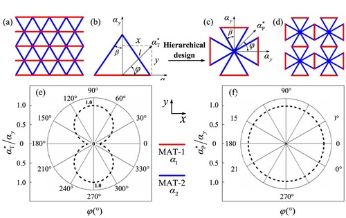
The polar plot in (e) obviously reveals that the in-plane programmable CTE is anisotropic. The CTE of the metamaterial in (a) shows an inherent in-plane directional dependence. The programmability of
is remarkably distinguishing along the different in-plane directions, raising a design complexity in the engineering applications. In order to further resolve this unexpected anisotropy, as given in (c, d), a hierarchical design is developed to construct a kind of planar bi-material metamaterial. Indeed, the hierarchical cell in (c) exactly includes four triangles with a shared vertex. Besides, the height directions of the four triangles are respectively along the orthogonal axis. By fulfilling the constraint
, the thermal deformation of each triangle will not overlap, and the CTEs of the hierarchical cell along x and y directions are both equal to
as shown in (c), suggesting the metamaterial presents the programmable CTE by modulating
and
.
Furthermore, the in-plane CTE along an arbitrary angle
for the planar metamaterial was expressed by Equation (2). The polar plot of
in (f) indicates that the hierarchical design successfully enables the planar metamaterial to present the isotropic programmable CTE. That is the application of this planar metamaterial could exclude the extra consideration of the directional dependence of the CTE, benefiting both the design and fabrication.
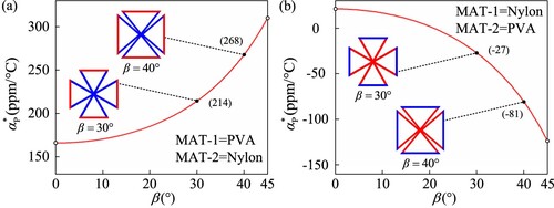
Subsequently, this work focuses on the additive manufacturing and CTE tests of this planar metamaterial, aiming at providing the fabrication and experimental basis to the engineering applications. Considering the additive manufacturing as described in Section 2.2, two kinds of polymers: nylon and polyvinyl alcohol (PVA) were selected as the basic materials, since the nylon has a large CTE, leading to the relative large difference of the CTE in these two polymers compared with the others (Raminhos, Borges, and Velhinho Citation2019). According to their CTEs and Equation (2), the theoretical predictions of the programmable CTEs are given in , in which the large positive CTE is achieved by an arrangement of MAT-1 = PVA and MAT-2 = Nylon. Oppositely, a wide range of negative CTE is also obtained in an arrangement of MAT-1 = Nylon and MAT-2 = PVA. Especially, (a, b) respectively illustrates two cells with two specific values of ,
and corresponding target CTEs. These cells are used in the additive manufacturing and experimental test presented in the following sections. Here, the polymers were used to identify the prototype of the planar metamaterial. The programming mechanism actually enables the planar metamaterial to incorporate universal engineering materials, providing that these materials fulfil the requirement of the additive manufacturing.
Figure 2. The theoretical plots of the CTE for the planar metamaterial to design the (a) large positive CTE with MAT-1 = PVA, MAT-2 = Nylon, and the (b) large negative CTE with MAT-1 = Nylon, MAT-2 = PVA. The cells with specific and target CTEs are illustrated.
2.2. Additive manufacturing
It should be noted that the underlying mechanism of the programmable CTE in the planar metamaterial is the coordinating thermal deformation of the mandatorily required two materials. These materials are required to have a large difference in CTE. Then, this inherent characteristic forces the planar metamaterial should integrate and connect two kinds of different materials. Usually, the traditional manufacturing processes, including the welding, gluing and bolting, will inevitably introduce the complicated procedures and other additional unexpected impurities at the interfaces of two materials. Hence, the metamaterials fabricated by these processes are relatively rough, and the CTEs are in quite a limited range.
Here, the additive manufacturing is used to integratedly fabricate the designed planar metamaterial (Vafadar et al. Citation2021; Goh, Sing, and Yeong Citation2021). A material extrusion based 3D printer: Ultimaker S5 was used, as it incorporated the ability to simultaneously fuse and deposit two polymer filaments. The nylon filament was printed by a nozzle with the diameter of 0.25 mm, the raster width of 0.23 mm and temperature of 230.0°C. Simultaneously, the PVA filament was printed by a nozzle with the diameter of 0.4 mm, raster width of 0.35 mm and temperature of 215.0°C. The extrusion speed was 20.0 mm/s, and the layer thickness was unified as 0.06 mm. To improve the quality, the patterns of concentric and lines were used for the nylon and PVA, respectively. The wall printing order was purposely set as outer before inner to raise the dimensional accuracy for the outer profiles. As the adjacent walls generally push each other, the wall that printed first will be solidified and suffered less push. Therefore, printing the outer wall first will make the outer walls be in a more accurate location. Besides, the retraction technique was used to reduce the wiredrawing, which always generates the undesired mixtures. To actually terminate the material from flowing, it needs to retract the material out of the nozzle, making clean travel moves without stringing. The building plate adhesion type was enabled as Brim with three layers in order to prevent the warping effect. A brim is a single layer flat area around the base of the metamaterial to make the contact area between the metamaterial and build plate to be adequate.
The planar metamaterials with multi cells were designed and printed as shown in (b, d). Besides, the corresponding unit cells were also additively manufactured to conduct subsequent CTE tests. It is well known that the performance of the metamaterial, periodically arrayed by unit cells, can be analyzed by its representative unit cell. Especially, in order to mark the black–white speckles for the digital image correlation (DIC) calculation to obtain the thermal displacements, a semi-circle with appropriate radius is added to each base member as illustrated in (a, c). Corresponding to the geometrical illustration in (a, b), the detailed geometrical dimensions, material arrangement and target CTEs for each unit cell are listed in . For all cells, the length L1 of the base members is kept to be constant of 62.5 mm, while the length L2 of the side members are determinated by the the geomertical relationship between L1 and . The radius of the semi-circles is proportionally varied with the overall dimension of the cells. The rectangle cross-section of the members is of width t = 2.0 mm and depth b = 3.0 mm to keep the members slender. Considering that the over small value of
will lead to the low magnitude of the CTEs, while the large value of
will result in overlap of the members in the thermal deformation. Thus, two appropriate values of
were selected. The target positive CTEs are as high as 204 and 268 ppm/°C, while the negative CTEs are designed to be −25 and −77 ppm/°C.
Figure 3. Illustration of the dimension and additional four semi-circles for the unit cells with (a) positive and (c) negative CTEs. Additively manufactured planar metamaterial and corresponding unit cells to program (b) positive and (d) negative CTE.
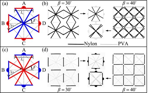
Table 1. The geometrical dimensions of the designed planar bi-material metamaterial with the positive and negative programmable CTEs.
3. Experiment
3.1. Device and verification
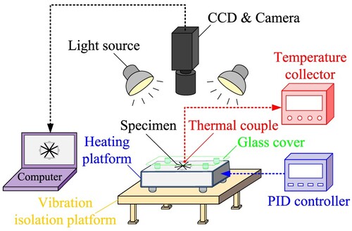
An experimental device, which is mainly based on the digital image processing, is shown in , as the planar metamaterial cannot fulfill the standard of the thermal expansion test by the commercial instrument. The main testing principle is that the metamaterial is heated to a target temperature by a heating platform (PCE-E600) which is controlled by a PID. The upper surface of the heating platform is made of the Zerodur. The extremely low CTE and smooth characteristics of the Zerodur benefit to avoid the extra thermal deformation and friction in the experiments. The images before and after heating are captured by a CCD (Point Grey GS3-PGE-91S6M, 3376 × 2704 pixel). The temperature of the metamaterial is measured by the thermal couples (K-type) and is recorded by a temperature collector (NAPUI130T-16). Two light sources are used to supplement the uniform optical field, and a glass cover is placed above the metamaterial to prevent the heat convection to the camera. A computer (Thinkpad T470) is used to control the CCD as well as to capture the images. Besides, the thermal displacements are calculated on the computer by using an open source digital image correlation code ncorr (CitationBlaber).
Figure 4. An experimental device, which is mainly based on the digital image processing method, is used to conduct the CTE test.
In order to verify the reliability and accuracy of this experimental device, the CTEs for three kinds of commonly used engineering alloys: aluminium alloy Al7075, titanium alloy TC4 and stainless steel 316L were experimentally measured. As shown in , the panels of these three alloys were cut with the dimensions of 150 × 150 × 5 mm, and were sprayed with appropriate white–black speckles. The heating temperature was increased from the room temperature (RT) up to 200.0°C, and the captured images were used in the DIC calculation, in which 1840 × 1840 pixel was set as the region of interest, and the subset was set as 41 × 41 pixel.
Figure 5. The panels (150 × 150 × 5 mm) for the (a) aluminium alloyAl7075 (b) titanium alloyTC4 and (c) stainless steel 316L with marked white-black speckles used in the test.
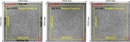
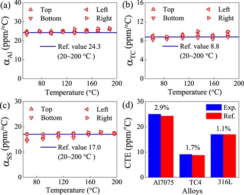
As marked in (a) for a representative, the CTEs of the alloys were measured along the four sides in the region of interest. According to the definition of linear coefficient of thermal expansion, the measured CTEs are summarised in (a–c), in which the reference values of the CTEs in the temperature range of 20–200°C (Wei et al. Citation2016) are included for comparison. Obviously, the measured scatters along the four sides present the good consistence with each other. Most importantly, the scatters keep closely to the lines, suggesting that the CTEs measured by the experimental device are in good accordance with the reference values. Furthermore, as shown in (d), the experimentally measured columns, which are the average values of the CTEs along the four sides, are compared with the reference values. The relative deviations are as low as 2.9%, 1.7% and 1.1% for the Al7075, TC4 and 316L, respectively, demonstrating the effectiveness of the experimental device and the measuring strategy used in this work. Hence, this experimental device and method was used in subsequent CTE test for the additively manufactured planar metamaterial.
Figure 6. The comparison of the CTEs between the experimental measurements along four sides and reference values for (a) aluminium alloy Al7075 (b) titanium alloy TC4 and (c) stainless steel 316L. (d) The averaged experimental CTEs.
3.2. Thermal expansion test
The CTEs of the planar metamaterials were systematically tested, especially in the different in-plane directions. The heating temperature was from the RT to 60°C. The images and temperatures were well captured. The thermal displacements induced by the temperature increment were calculated by DIC for the semi-circles with the marked white–black speckles. The CTE of the planar metamaterial is calculated as:
(3)
(3) where T0 = RT and T = 60°C are the initial and target temperatures. X and Y are the initial coordinates. U and V are the thermal displacements. L and
are the initial length and thermal expansion, respectively. The subscripts i and j are the measuring points. As illustrated in (a, d), the centres of the four semi-circles, which are marked as A, B, C and D, are used as the measuring points. Thus, a number of CTEs between arbitrary two measuring points are measured. For instance,
and
represent the CTEs measured from the points B to D and points C to A. Besides, the vector, which is defined from the starting and ending measuring points, determinates a specific directional angle
referred to the x axis. For instance, vectors
and
have the in-plane directional angle of
and
, respectively. Then,
and
are the CTEs along directions of
and
. Similarly, CTEs along other in-plane directions are also measured and are discussed in Section 4.2.
4. Results and discussion
4.1. Thermal deformation
The thermal displacements U and V for the planar metamaterials with the positive programmable CTE were calculated for all four semi-circles. As the representatives, the thermal displacement U along x direction in the left and right semi-circles and the displacement V along the y direction in the up and down semi-circles are summarised in . Typically, considering the coordinate in these figures, the contours clearly reveal that the left and right semi-circles suffer the thermal displacement U along the negative and positive x direction, respectively, firmly suggesting the positive thermal expansion along the horizontal direction. Similarly, the up and down semi-circles present the distinguished thermal displacement V along the negative and positive y direction, respectively, revealing the positive thermal expansion in the vertical direction.
Figure 7. The thermal displacements U and V along x and y directions, respectively for the metamaterial with positive programmable CTE (members fabricated by nylon have the same black colour with that of heating platform).
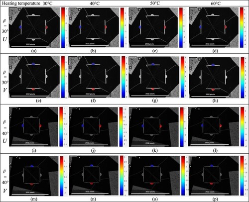
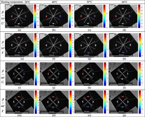
On the other hand, for the planar metamaterials with the negative programmable CTE, the thermal displacements are summarised in . The contour plots indicate that the left and right semi-circles induce the thermal displacement U along the positive and negative x direction, respectively. That is, the negative thermal expansion along the horizontal direction is generated. Similarly, the negative thermal expansion along the vertical direction can be also obtained. These thermal displacement evolutions in and illustrate the expected thermal expansion and lay the foundation to generate the predicted either positive or negative programmable CTEs. Additionally, it is observed that the interfaces of the members with different materials were not separated before and after the CTE tests up to 60.0°C, demonstrating the reliability of the additive manufacturing.
Figure 8. The thermal displacements U and V along x and y directions, respectively for the metamaterial with negative programmable CTE (members fabricated by nylon have the same black colour with that of heating platform).
4.2. Programmable coefficient of thermal expansion
As mentioned in Section 3.2, the experimental CTEs for the planar metamaterials in the temperature range of RT-60°C were measured in various in-plane directions including ,
,
,
,
,
,
and
. Since
and
were measured by the same two measuring points, they should have the same values. The similar situation is applicable for
and
. Furthermore, for purpose of well comparing the experimental measurements and theoretical prediction
as listed in , the measured CTEs are normalised by
. For instance,
is the normalised CTE along the direction
. Then, all normalised CTEs in various directions are summarised in a polar like plot .
Figure 9. The normalised CTEs which are the ratios of the experimental measurements to the theoretical predictions in the various in-plane directions. The angle and theoretical prediction
are (a)
,
ppm/°C, (b)
,
ppm/°C, (c)
,
ppm/°C and (d)
,
ppm/°C.
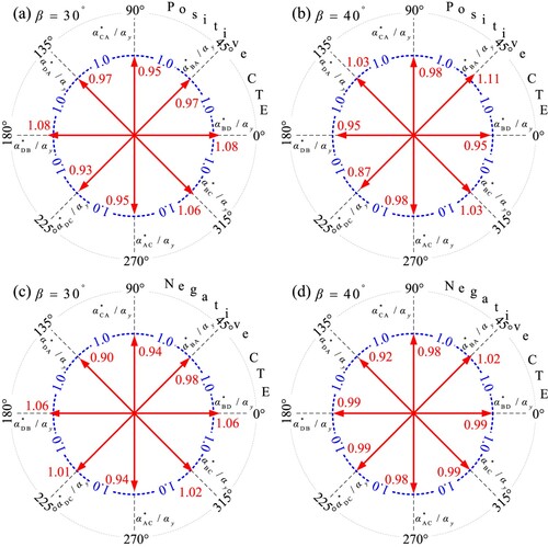
As illustrated in (a), for the planar metamaterial (), in which the nylon and PVA are arranged in the side and base members, respectively, the normalised CTEs in various in-plane directions are in the range of 0.93∼1.08. The relative deviation range is only −7.0% to +8.0%. Similarly, the normalised CTEs in (b) for
are in the range of 0.87–1.11, which means the relative deviation is of −13.0% to +11.0%. When the nylon and PVA are arranged in the base and side members, respectively, for
, (c) indicates the relative deviation is in the range of only −10.0%∼+6.0%, while the deviation for the metamaterial of
is also as low as −8.0% to +2.0% in (d). Indeed, in the theory, the members in the metamaterial are idealised as the lines without any volume. Besides, the joints of the members are regarded as pin jointed. However, in the additively manufactured metamaterial, the members are solid with the certain depth and width. Most importantly, the bonded joints in the manufactured metamaterial, which are different from the pin joints, will introduce rotational resistance to the thermal deformation. Therefore, above differences between the theory and practical experiments should be responsible for the deviations between the theoretical predictions and experimental results.
For every tested planar metamaterial, the normalised CTEs in the different in-plane directions are in a good consistency to each other, verifying that the planar metamaterial exactly presents the in-plane programmable CTE as predicted in Section 2.1. That is even the bi-material triangle ((b)) presents a significant anisotropy, the purposely and rationally devised hierarchical cell ((c)) and the corresponding planar metamaterial commendably realises the same programmable CTE in the arbitrary in-plane directions. Indeed, the hierarchical cell exactly includes four triangles with a shared vertex. Besides, the height directions of the four triangles are respectively along the orthogonal axis. This comparison practically demonstrates the reliability of the additive manufacturing as well as the effectiveness of the CTE tests for the planar metamaterial.
The CTE averaged from all directions is 204 and 258 ppm/°C for the planar metamaterials with and
, respectively in (a, b). That is even though the CTEs of the basic polymers nylon and PVA are only 166.0 and 21.0 ppm/°C, the design of the planar metamaterial significantly amplifies the positive magnitudes of the programmable CTE. Most importantly, in (c, d), the average CTEs for the planar metamaterial with
and
are in the negative values of −25 and −77 ppm/°C. The relative concise approach of the architecture design is realised in the planar metamaterial. Then, the coordinating thermal deformation of the commonly available materials, which just have positive CTEs, enables the large magnitudes of negative CTEs to be easily achieved.
4.3. Discussion
Actually, the manufacturing and experimental measurements are the important basis to the engineering applications of the mechanical metamaterials. Programming the CTE should well balance the expected modulating range and complexity of the manufacturing. summarises a comparison of the quasi-isotropic CTEs between the literature reported metamaterials and the hierarchical metamaterial in this work. As illustrated in the figure, the traditional manufacturing processes, such as casting and forming etc, are widely used to fabricate the bulk materials including typical alloys and polymers. These processes are relatively mature, while the bulk materials always possess the constant CTEs in a limited range around −101 to +102 ppm/°C, for instance, Al 7075: 24.5 ppm/°C, TC4: 8.8 ppm/°C, 316L: 17.0 ppm/°C, nylon: 166.0 ppm/°C and PVA: 21.0 ppm/°C. Then, the manufacturing of the engineering structures by the sole bulk material will not face the challenge of integrating two different materials, while the CTEs of these structures can hardly be programmed.
Figure 10. Comparison of the metamaterials with quasi-isotropic CTEs between the literatures reported and explored in this work. 2D metamaterials with Al/Ti (Berger et al. Citation2011; Gdoutos, Shapiro, and Daraio Citation2013; Steeves et al. Citation2007), Al/Invar (Wei et al. Citation2016), Al/W (Xie, Pei, and Yu Citation2018) and 3D metamaterials with Al/Ti (Xu and Pasini Citation2016) were fabricated by welding, mechanical fitting and assembling. 2D metamaterial with Al/ABS (Hopkins et al. Citation2016) and 3D metamaterial with PEGDA/Copper (Wang et al. Citation2016) were fabricated by projection microstereolithography. 3D micro metamaterial was fabricated by using gray-tone laser lithography (Qu et al. Citation2017).
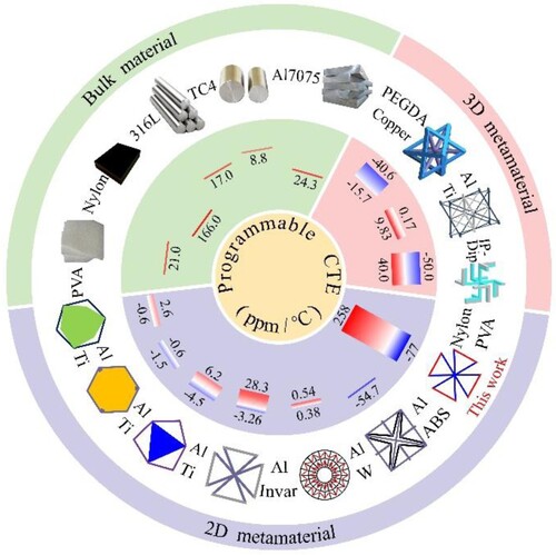
In contrast, unlike the bulk materials, the main principle of the mechanical metamaterials is the exquisite structural design of the unique architectures in either micro or macro scales. Hence, as illustrated in , the 2D and 3D metamaterials exclusively present the quasi-isotropic programmable CTEs including even negative values, even though their basic materials have positive CTEs. As mentioned before, these metamaterials should mandatorily integrate and connect two kinds of different materials. Besides, the cellular characteristic of the architectures in these metamaterials also requires the relatively complicated and refined manufacturing process. Then, the previous works reported the welding and mechanical fitting processes to integrate the Al/Ti (Das, Jacobs, and Barbour Citation2010; Gdoutos, Shapiro, and Daraio Citation2013; Steeves et al. Citation2007; Xu and Pasini Citation2016), Al/Invar (Wei et al. Citation2016), Al/W (Xie, Pei, and Yu Citation2018) into the 2D and 3D metamaterials. The experimentally measured CTEs were only in the range of [−4.5, +28.3] ppm/°C, which was far narrower than the theoretical predictions. Further, benefiting from the rapid development of the additive manufacturing, the projection micro stereolithography was used to fabricate the 2D metamaterial by the Al/ABS (Hopkins et al. Citation2016) and the 3D metamaterial by the PEGDA/Copper (Wang et al. Citation2016). Additionally, a 3D two-component polymer micro metamaterial was fabricated by using the gray-tone laser lithography (Qu et al. Citation2017). The obtained CTEs were still in a limited range of [−54.7, +40.0] ppm/°C.
In this work, the planar metamaterial is fabricated by the material extrusion based additive manufacturing. The raw materials nylon and PVA are widely available. Most importantly, the programmable CTE is experimentally verified to be identical in various in-plane directions, and is pronouncedly expanded to be [−77, +258] ppm/°C, far beyond the literature results. This wide range of CTE provides more design freedom and margin. It is expected that the additive manufacturing and experimental test established here can be explored for the 3D metamaterials in future works. Besides, the CTE scalability of the metamaterial is defined as the ratio of the maximum magnitude (absolute value) of the CTE obtained by the metamaterial and the maximum CTE of the ingredient materials. It should be noted that the CTE scalability, which reflects the structural effect of the metamaterials, is highly related to the CTE and contrast of the CTE of the two ingredient materials. Thus, as shown in , considering the CTE of the aluminium alloy, the 2D metamaterials with Al/Ti have the CTE scalability of 0.106, 0.0617 and 0.255. Similarly, the CTE scalabilities for the 2D metamaterials with Al/Invar, Al/W and Al/ABS are 1.164, 0.0222 and 0.547, respectively. The corresponding values for the 3D metamaterials with IP-Drip, Al/Ti and PEGDA/Copper are 0.833, 0.404 and 0.260, respectively. Then, according to the maximum CTE 258 ppm/°C and the CTE of the nylon 166 ppm/°C, the CTE scalability in the metamaterial of this work is about 1.55.
The programming mechanism, as described in Section 2, indeed provides the additive manufacture of this planar metamaterial to comprise a universality of the available engineering materials, including metal alloys (Liu et al. Citation2020), polymers (Huang et al. Citation2020), ceramics (Ma et al. Citation2020) and composites (Lu et al. Citation2019) etc. Then the multi-functions of high strength/stiffness, low density as well as elevated working temperature can be further integrated. This can be further explored, once the combinations of these engineering materials will be well additively manufactured in the future.
5. Concluding remarks
In this work, a planar metamaterial, based on the hierarchical design of the multi bi-material triangle unit, was constructed to program the in-plane isotropic CTE. With two widely available polymers: nylon and PVA, the material extrusion based additive manufacturing was used to fabricate the devised planar metamaterial. An experimental device, based on the digital image processing, was used to perform the CTE test. The integrity of the planar metamaterial is well reserved, as the interfaces of the different polymer members are not separated before and after the CTE tests, demonstrating the reliability of the additive manufacturing. The normalised CTEs in different in-plane directions are in good consistency to each other, experimentally verifying that the planar metamaterial realises the in-plane programmable CTE in various directions. The values of the normalised CTE all closely approach to 1.0, and the relative deviation is only within −13.0% to +11.0%, revealing the theoretical predictions of the planar metamaterial are effectively verified by the experiments. When the base and side members are arranged as PVA andnylon, the programmable CTE achieves the positive values of 204 and 258 ppm/°C. Otherwise, when the nylon and PVA are arranged in the base and side members, the negative CTEs of −25 and −77 ppm/°C are exclusively obtained. The programmable CTE is pronouncedly expanded to be [−77, +258] ppm/°C, far beyond the literature results, providing more design freedom and margin, and supplementing the feasibility to the applications where the thermal expansion control or shape morphing are needed.
Acknowledgements
The authors are grateful for the support by the National Natural Science Foundation of China under grant #11972154 and #51875581.
Disclosure statement
No potential conflict of interest was reported by the author(s).
Additional information
Funding
Notes on contributors
Kai Wei
Kai Wei is an Associate Professor in State Key Laboratory of Advanced Design and Manufacturing for Vehicle Body of Hunan University. Kai Wei is mainly working on additive manufacturing for multi-functional materials and structures.
Xiaoyujie Xiao
Xiaoyujie Xiao is currently a master student in State Key Laboratory of Advanced Design and Manufacturing for Vehicle Body of Hunan University. Xiaoyujie Xiao is mainly studying on the advanced fabrication process of multi-material structures and the measurement strategy of thermal expansion.
Wentao Xu
Wentao Xu is currently a master student in State Key Laboratory of Advanced Design and Manufacturing for Vehicle Body of Hunan University. Wentao Xu is mainly studying on the design and mechanical analysis of the functional metamaterials and metastructures.
Zhengtong Han
Zhengtong Han is currently a PhD candidate in State Key Laboratory of Advanced Design and Manufacturing for Vehicle Body of Hunan University. Zhengtong Han is mainly studying and working on topology optimisation method for multi-material metamaterials.
Yazhuo Wu
Yazhuo Wu is a master’s degree graduate in State Key Laboratory of Advanced Design and Manufacturing for Vehicle Body of Hunan University. Yazhuo Wu was worked on the design and finite element analysis for the functional structures.
Zhonggang Wang
Zhonggang Wang is an Associate Professor in School of Traffic & Transportation Engineering of Central South University. Zhonggang Wang is mainly working on functional design, manufacturing process and characterisation of cellular structures.
References
- Ai, L., and X. L. Gao. 2017. “Micromechanical Modeling of 3D Printable Interpenetrating Phase Composites with Tailorable Effective Elastic Properties Including Negative Poisson’s Ratio.” Journal of Micromechanics and Molecular Physics 02 (04): 1750015. doi:10.1142/S2424913017500151.
- Berger, J., C. Mercer, R. M. McMeeking, and A. G. Evans. 2011. “The Design of Bonded Bimaterial Lattices That Combine Low Thermal Expansion with High Stiffness.” Journal of the American Ceramic Society 94: S42–S54. doi:10.1111/j.1551-2916.2011.04503.x.
- Blaber, J. “Ncorr.” http://www.ncorr.com/.
- Chen, J., L. Fan, Y. Ren, Z. Pan, J. Deng, R. Yu, and X. Xing. 2013. “Unusual Transformation from Strong Negative to Positive Thermal Expansion in PbTiO3-BiFeO3 Perovskite.” Physical Review Letters 110 (11): 115901. doi:10.1103/PhysRevLett.110.115901.
- Das, D., T. Jacobs, and L. J. Barbour. 2010. “Exceptionally Large Positive and Negative Anisotropic Thermal Expansion of an Organic Crystalline Material.” Nature Materials 9 (1): 36–39. doi:10.1038/Nmat2583.
- Gdoutos, E., A. A. Shapiro, and C. Daraio. 2013. “Thin and Thermally Stable Periodic Metastructures.” Experimental Mechanics 53 (9): 1735–1742. doi:10.1007/s11340-013-9748-z.
- Goh, G. D., S. L. Sing, and W. Y. Yeong. 2021. “A Review on Machine Learning in 3D Printing: Applications, Potential, and Challenges.” Artificial Intelligence Review 54: 63–94. doi:10.1007/s10462-020-09876-9.
- Han, C. J., Q. H. Fang, Y. S. Shi, S. B. Tor, C. K. Chua, and K. Zhou. 2020. “Recent Advances on High-Entropy Alloys for 3D Printing.” Advanced Materials 32 (26): 1903855. doi:10.1002/adma.201903855.
- Hopkins, J. B., Y. P. Song, H. Lee, N. X. Fang, and C. M. Spadaccini. 2016. “Polytope Sector-Based Synthesis and Analysis of Microstructural Architectures with Tunable Thermal Conductivity and Expansion.” Journal of Mechanical Design 138: 5. doi:10.1115/1.4032809.
- Huang, J., Q. Chen, H. Jiang, B. Zou, L. Li, J. Liu, and H. Yu. 2020. “A Survey of Design Methods for Material Extrusion Polymer 3D Printing.” Virtual and Physical Prototyping 15 (2): 148–162. doi:10.1080/17452759.2019.1708027.
- Jefferson, G., T. A. Parthasarathy, and R. J. Kerans. 2009. “Tailorable Thermal Expansion Hybrid Structures.” International Journal of Solids and Structures 46 (11-12): 2372–2387. doi:10.1016/j.ijsolstr.2009.01.023.
- Lakes, R. 2007. “Cellular Solids with Tunable Positive or Negative Thermal Expansion of Unbounded Magnitude.” Applied Physics Letters 90 (22): 221905. doi:10.1063/1.2743951.
- Liu, D. H., D. J. Wu, G. Y. Ma, C. L. Zhong, F. Y. Niu, A. Gasser, J. H. Schleifenbaum, and G. J. Bi. 2020. “Effect of Post-Deposition Heat Treatment on Laser-Tig Hybrid Additive Manufactured Al-Cu Alloy.” Virtual and Physical Prototyping 15 (4): 445–459. doi:10.1080/17452759.2020.1818021.
- Lu, Z. L., J. W. Cao, Z. Q. Song, D. C. Li, and B. H. Lu. 2019. “Research Progress of Ceramic Matrix Composite Parts Based on Additive Manufacturing Technology.” Virtual and Physical Prototyping 14 (4): 333–348. doi:10.1080/17452759.2019.1607759.
- Ma, C., C. He, W. L. Wang, X. Y. Yao, L. W. Yan, F. Hou, J. C. Liu, and A. R. Guo. 2020. “Metal-Doped Polymer-Derived Sioc Composites with Inorganic Metal Salt as the Metal Source by Digital Light Processing 3D Printing.” Virtual and Physical Prototyping 15 (3): 294–306. doi:10.1080/17452759.2020.1752967.
- Meng, Z. J., J. K. He, J. X. Li, Y. W. Su, and D. C. Li. 2020. “Melt-Based, Solvent-Free Additive Manufacturing of Biodegradable Polymeric Scaffolds with Designer Microstructures for Tailored Mechanical/Biological Properties and Clinical Applications.” Virtual and Physical Prototyping 15 (4): 417–444. doi:10.1080/17452759.2020.1808937.
- Miller, W., D. S. Mackenzie, C. W. Smith, and K. E. Evans. 2008. “A Generalised Scale-Independent Mechanism for Tailoring of Thermal Expansivity: Positive and Negative.” Mechanics of Materials 40 (4-5): 351–361. doi:10.1016/j.mechmat.2007.09.004.
- Miller, W., C. W. Smith, D. S. Mackenzie, and K. E. Evans. 2009. “Negative Thermal Expansion: A Review.” Journal of Materials Science 44 (20): 5441–5451. doi:10.1007/s10853-009-3692-4.
- Monroe, J. A., D. Gehring, I. Karaman, R. Arroyave, D. W. Brown, and B. Clausen. 2016. “Tailored Thermal Expansion Alloys.” Acta Materialia 102: 333–341. doi:10.1016/j.actamat.2015.09.012.
- Oruganti, R. K., A. K. Ghosh, and J. Mazumder. 2004. “Thermal Expansion Behavior in Fabricated Cellular Structures.” Materials Science and Engineering A-Structural Materials Properties Microstructure and Processing 371 (1-2): 24–34. doi:10.1016/S0921-5093(03)00054-6.
- Qu, J. Y., M. Kadic, A. Naber, and M. Wegener. 2017. “Micro-Structured Two-Component 3D Metamaterials with Negative Thermal-Expansion Coefficient from Positive Constituents.” Scientific Reports 7. doi:10.1038/srep40643.
- Raminhos, J. S., J. P. Borges, and A. Velhinho. 2019. “Development of Polymeric Anepectic Meshes: Auxetic Metamaterials with Negative Thermal Expansion.” Smart Materials and Structures 28: 4. doi:10.1088/1361-665X/ab034b.
- Steeves, C. A., S. L. D. S. E. Lucato, M. He, E. Antinucci, J. W. Hutchinson, and A. G. Evans. 2007. “Concepts for Structurally Robust Materials That Combine Low Thermal Expansion with High Stiffness.” Journal of the Mechanics and Physics of Solids 55 (9): 1803–1822. doi:10.1016/j.jmps.2007.02.009.
- Takenaka, K. 2018. “Progress of Research in Negative Thermal Expansion Materials: Paradigm Shift in the Control of Thermal Expansion.” Frontiers in Chemistry 6: 267. doi:10.3389/fchem.2018.00267.
- Taniker, S., R. Celli, D. Pasini, D. C. Hofmann, and C. Daraio. 2020. “Temperature-Induced Shape Morphing of Bi-Metallic Structures.” International Journal of Solids and Structures 190: 22–32. doi:10.1016/j.ijsolstr.2019.10.024.
- Vafadar, A., F. Guzzomi, A. Rassau, and K. Hayward. 2021. “Advances in Metal Additive Manufacturing: A Review of Common Processes, Industrial Applications, and Current Challenges.” Applied Sciences 11 (3): 1213. doi:10.3390/app11031213.
- Wang, Q. M., J. A. Jackson, Q. Ge, J. B. Hopkins, C. M. Spadaccini, and N. X. Fang. 2016. “Lightweight Mechanical Metamaterials with Tunable Negative Thermal Expansion.” Physical Review Letters 117: 17. doi:10.1103/PhysRevLett.117.175901.
- Wei, K., H. S. Chen, Y. M. Pei, and D. N. Fang. 2016. “Planar Lattices with Tailorable Coefficient of Thermal Expansion and High Stiffness Based on Dual-Material Triangle Unit.” Journal of the Mechanics and Physics of Solids 86: 173–191. doi:10.1016/j.jmps.2015.10.004.
- Wei, K., Y. Peng, W. B. Wen, Y. M. Pei, and D. N. Fang. 2017. “Tailorable Thermal Expansion of Lightweight and Robust Dual-Constituent Triangular Lattice Material.” Journal of Applied Mechanics-Transactions of the Asme 84: 10. doi:10.1115/1.4037589.
- Wu, L., B. Li, and J. Zhou. 2016. “Isotropic Negative Thermal Expansion Metamaterials.” ACS Applied Materials & Interfaces 8 (27): 17721–17727. doi:10.1021/acsami.6b05717.
- Wu, H., Y. J. Ren, J. Y. Ren, A. H. Cai, M. Song, Y. Liu, X. L. Wu, et al. 2020. “Effect of Melting Modes on Microstructure and Tribological Properties of Selective Laser Melted Alsi10 mg Alloy.” Virtual and Physical Prototyping 15: 570–582. doi:10.1080/17452759.2020.1811932.
- Xie, Y., X. Pei, and J. J. Yu. 2018. “Double-Layer Sandwich Annulus with Ultra-Low Thermal Expansion.” Composite Structures 203: 709–717. doi:10.1016/j.compstruct.2018.07.075.
- Xu, H., and D. Pasini. 2016. “Structurally Efficient Three-Dimensional Metamaterials with Controllable Thermal Expansion.” Scientific Reports 6. doi:10.1038/srep34924.
- Yamamoto, N., E. Gdoutos, R. Toda, V. White, H. Manohara, and C. Daraio. 2014. “Thin Films with Ultra-Low Thermal Expansion.” Advanced Materials 26 (19): 3076–3080. doi:10.1002/adma.201304997.
- Yang, Q. D., K. Wei, X. J. Yang, H. Q. Xie, Z. L. Qu, and D. N. Fang. 2020. “Microstructures and Unique Low Thermal Expansion of Invar 36 Alloy Fabricated by Selective Laser Melting.” Materials Characterization 166. doi:10.1016/j.matchar.2020.110409.
- Zhengchun, D., Z. Mengrui, W. Zhiguo, and Y. Jianguo. 2016. “Design and Application of Composite Platform with Extreme Low Thermal Deformation for Satellite.” Composite Structures 152: 693–703. doi:10.1016/j.compstruct.2016.05.073.
- Zhu, H. X., T. X. Fan, Q. Peng, and D. Zhang. 2018. “Giant Thermal Expansion in 2D and 3D Cellular Materials.” Advanced Materials 30: 18. doi:10.1002/adma.201705048.
- Zolfagharian, A., M. A. P. Mahmud, S. Gharaie, M. Bodaghi, A. Z. Kouzani, and A. Kaynak. 2020. “3D/4D-Printed Bending-Type Soft Pneumatic Actuators: Fabrication, Modelling, and Control.” Virtual and Physical Prototyping 15 (4): 373–402. doi:10.1080/17452759.2020.1795209.