
 ?Mathematical formulae have been encoded as MathML and are displayed in this HTML version using MathJax in order to improve their display. Uncheck the box to turn MathJax off. This feature requires Javascript. Click on a formula to zoom.
ABSTRACT
Laser powder bed fusion (LPBF) additive manufacturing has been advancing in the fabrication of metallic multi-material structures with intricate structures and refined material layouts. Herein, a comprehensive review of the recent achievements of multi-material structures via LPBF is provided in terms of interface characteristics and strengthening methods, critical technical issues and potential applications. It begins with the introduction of multi-material structures and the scope of the review. The interface characteristics (including representative multi-material types printed by LPBF, interfacial microstructure, defects, etc.) and strengthening methods of multi-material structures are then presented. Thereafter, the critical technical issues in LPBF for multi-material structures are discussed with regard to equipment development, data preparation, thermodynamic calculation and process simulation, and powder cross-contamination and recycling. Moreover, the potential applications (particularly in biomedical, electronic, aerospace) are illustrated and discussed. Finally, the outlook is outlined to provide guidance for future research.
1. Introduction
A multi-material part is composed of multiple materials physically distributed within the part, which can integrate the structures and functions of various materials to achieve tailorable properties (local wear resistance, high thermal conductivity, thermal insulation, chemical corrosion resistance, etc.) at the predetermined locations of the part (Wei, Zhang et al. Citation2020). The specific distribution of multiple materials within a part can achieve superior performance than a single-material part. In particular, some products serve under harsh working conditions where multi-functionalities and multi-environmental adaptability are required (Vassilakos, Giannatsis, and Dedoussis Citation2021). For instance, IN718/316L multi-material structures can achieve high heat resistance and oxidation resistance to high temperatures as well as sufficient mechanical strength and toughness for low temperatures, thus providing great potential in the aerospace field (Wits and Amsterdam Citation2021); NiTi/Ti6Al4 V multi-material structures are potentially applicable to biomedical orthopedic implants with personalisation, comparable stiffness to human bones, and superior wear and corrosion resistance (Bartolomeu et al. Citation2020). Therefore, the multi-material structures can pave a pathway toward the integral manufacturing of end-use parts with innovative structures and multi-material layouts, and fulfil the increasing demands from the aerospace, biomedical, automotive, and moulding industries.
It is difficult to fabricate multi-material structures with complex geometries and controllable distributions of different material types or compositions using traditional manufacturing techniques such as powder metallurgy (Kumar Chauhan and Khan Citation2020), rolling (Manesh and Taheri Citation2005), welding (Tomashchuk et al. Citation2013), chemical vapour deposition (Jain et al. Citation2001), and diffusion bonding (Yilmaz and Çelik Citation2003). Additive manufacturing (AM) can provide high design freedom and the flexibility of fabricating complex parts based on a layer-by-layer principle (Han, Fang et al. Citation2020), which enables precise control of the spatial distributions of materials and thus holds great potential for the design and manufacturing of multi-material structures. Compared with conventional manufacturing techniques, multi-material AM can provide a more reliable method to manufacture geometrically complex multi-material components and reduce the manufacturing cost. In particular, the process introduces a higher level of design freedom, which is capable to control the directionality and variety of the material distribution within a complex three-dimensional (3D) space. Therefore, multi-material AM can achieve ‘the right materials printed in the right positions’ and ‘unique structures printed for unique functions’ (Gu, Shi et al. Citation2021).
The representative AM techniques for metal multi-material structures are laser powder bed fusion (LPBF) and laser directed energy deposition (L-DED) (Li et al. Citation2022). LPBF is a critical member of the AM family, which uses a high-energy intensity laser beam to selectively melt metal powder on a powder bed (Sing, Kuo et al. Citation2021; Tan, Shen et al. Citation2021). Compared with the L-DED process, the LPBF process can fabricate multi-material structures with more complex and finer structure due to its smaller laser spot and thinner layer thickness (Wei and Li Citation2021). This process has been increasingly applied to fabricate complex multi-material structures with a dimension error lower than 100 μm (Wu et al. Citation2019a), showing great potential in the fabrication of heat exchangers, electrical devices, hip implants, jewelries, combustion chambers, wear-resistant components, cutting tools, etc. (Bohidar, Sharma, and Mishra Citation2014; Li and Han Citation2018). The mechanical properties (tensile strength, bending strength, etc.) of LPBF-printed multi-material structures are depended on the interfacial bonding, which is determined by microstructures and defects at the interface. Defects such as pores and cracks can weaken the bonding strength of the multi-material structures, and the refined microstructure at the interface can enhanced the interfacial bonding (Chen, Yang et al. Citation2020; Wang, Lao et al. Citation2020). For instance, a great interfacial strength (up to 557 MPa) can be achieved in an LPBF-printed steel/copper multi-material structure due to the fine dendritic grains at its interface (Tan, Chew et al. Citation2021).
The multi-material structures for LPBF are dominantly produced from discrete multiple materials (Wei, Zhang et al. Citation2020) and composite materials (Zhao et al. Citation2021; Han, Babicheva et al. Citation2020; Yan et al. Citation2020). However, it is challenging to control the variation of different compositions at predetermined positions within a multi-material part using composite materials (Vaezi et al. Citation2013). Numerous efforts have been made on the printing strategy of discrete multiple materials. Currently, there are three main strategies to print multi-material structures with LPBF: (i) the LPBF process is conducted directly on a substrate, and a multi-material part is composed of the substrate and the printed layers (Azizi et al. Citation2019; Dolev, Osovski, and Shirizly Citation2021); (ii) a multi-material part is printed by changing another powder manually in a single printing process (Bai et al. Citation2020; Wei, Zeng et al. Citation2020); and (iii) powder feeding systems of an LPBF machine can be modified to print a multi-material part (Al-Jamal, Hinduja, and Li Citation2008; Wei, Chueh et al. Citation2019). In particular, the third strategy has been most promising in achieving a precise printing of dissimilar materials within one printable layer and between different layers through programming.
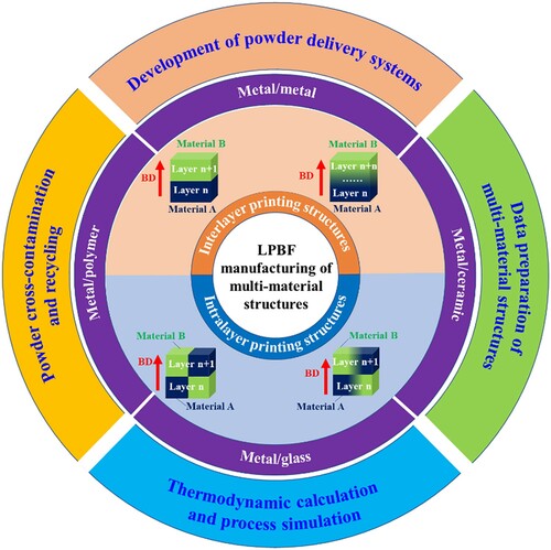
shows an overview of LPBF manufacturing of multi-material structures regarding their configurations, material types, and critical technical issues. According to the distribution of dissimilar materials, LPBF-printed multi-material structures can be categorised into interlayer- and intralayer-printed structures. The representative multi-material types are metal/metal, metal/ceramic, metal/glass, and metal/polymer. The achievement of a porosity- and crack-free interface with strong bonding is the most critical to these multi-material types. The critical technical issues in the multi-material LPBF process include the development of powder delivery systems, data preparation of multi-material structures before printing, thermodynamic calculation and process simulation, and powder cross-contamination and recycling.
Figure 1. Overview of LPBF manufacturing of multi-material structures, regarding their configurations, material types, and critical technical issues.
Recent reviews have reported multi-material structures fabricated via AM. Vaezi et al. (Citation2013) classified the multi-material AM processes and discussed their advantages and disadvantages, and technological obstacles. Bandyopadhyay and Heer (Citation2018) reviewed the multi-material AM processes of polymers and composites, metals and alloys, and metal/ceramic structures. Zhang, Chen et al. (Citation2019) provided a review focused on various functionally graded material (FGM) structures (Ti-based materials, Fe-based alloys, functionally graded porous scaffolds, ceramics, etc.). Han and Lee (Citation2020) reviewed different multi-material AM techniques and their applications (biomedical engineering, soft robotics, electronics, etc.). There are a few review papers focused on the multi-material LPBF process. Wei, Zhang et al. (Citation2020) reported progress of process/material characteristics and challenges in macro-, micro- and nano-scale laser-based multi-material AM for metals. Sing, Huang et al. (Citation2021) provided a comprehensive review for multi-material LPBF through in-situ alloying. Wei and Li (Citation2021) reviewed the material-spreading mechanisms, melt pool behaviour, and material characteristics in the LPBF processing of multi-material structures using metal/metal, metal/ceramic, and metal/polymer. Schneck et al. (Citation2021) investigated the implications of multi-material LPBF in the process chain, including the pre-process, in-process, and post-process.
In view of the increasingly significant roles in multi-material LPBF, there is still lack of discussion on the formation mechanisms of interfacial microstructure and defects as well as the strengthening methods for interfacial bonding. Additionally, the technical challenges (including equipment, data, process, material) in multi-material LPBF and its potential applications need to be comprehensively addressed. To this end, this article provides a comprehensive review of the multi-material structures via LPBF regarding interface characteristics (including the multi-material types, interfacial microstructure, defects, etc.) and strengthening methods of LPBF-printed multi-material structures, critical technical issues, and potential applications of printed products. After a brief introduction in Section 1, in Section 2, the interface characteristics of multi-material structures printed by LPBF including the representative multi-material types, interfacial microstructure and defects of multi-material structures will be reviewed, and the enhancement methods of the interface will be summarised and discussed. The critical technical issues in the LPBF process for multi-material structures will be presented and discussed in Section 3, including equipment development, data preparation, thermodynamic calculation and process simulation, and powder cross-contamination and recycling. Section 4 will illustrate the potential applications of multi-material structures via LPBF in various industries (particularly in biomedical, electronics, aerospace, and jewelry). Finally, Section 5 will conclude with perspectives on the challenges and opportunities in the development of multi-material LPBF.
2. Interface characteristics and strengthening methods
2.1. Multi-material types for LPBF
Recently, tremendous research has demonstrated the feasibility of the LPBF process for multi-material structures. lists the representative multi-material types printed by LPBF, which can be divided into four categories according to the combination of dissimilar materials, i.e. metal/metal, metal/ceramic, metal/glass, and metal/polymer. Among these multi-material types, metal/metal multi-material structures have been most popular in the LPBF printing (Bandyopadhyay and Heer Citation2018). The metal powder materials used in multi-material LPBF include iron-based alloys, titanium alloys, aluminium alloys, copper alloys, nickel-based alloys, and so on (Wei and Li Citation2021). 316L stainless steel (SS) and Ti6Al4 V are extensively used in LPBF-printed metal/metal multi-material structures (Bobbio et al. Citation2017; Liu et al. Citation2014; Mei et al. Citation2019). For metal/ceramic multi-material structures, ceramic materials are often used to improve the hardness and wear resistance of metal materials, and the insulating properties of ceramics can be used to manufacture metal/ceramic integrated electrical circuits and sensors (King et al. Citation2019; Liu and Shin Citation2019). However, it is challenging to fabricate metal/ceramic multi-material structures due to different atomic bonds, thermal expansion coefficients and poor wettability between metals and ceramics using powder bed AM techniques (Koopmann, Voigt, and Niendorf Citation2019; Zhou et al. Citation2019). The same challenge is also laid on the printing of metal/glass and metal/polymer multi-material structures (Cheon and Na Citation2014; Zhang et al. Citation2020).
Table 1. LPBF-printed multi-material structures with dissimilar materials.
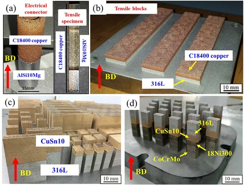
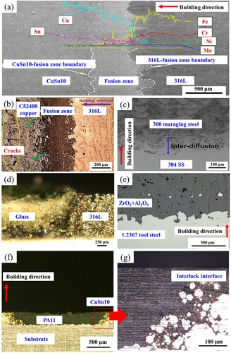
Currently, most studies have reported multi-material structures with the interlayer printing (). These multi-material structures are characterised by the changes of the material distribution in the build direction. The formation of the interface and its characteristics are still the priority to be investigated in interlayer LPBF-printed multi-material structures. Sing et al. (Citation2015) obtained good metallurgical bonding at the interface of Al/Cu laminates ((a)), and found the intermetallic compound Al2Cu at the interface. Liu et al. (Citation2014) produced the 316L/C18400 multi-material samples via LPBF ((b)), and a substantial amount of Fe and Cu element diffusion was observed at the 316L/C18400 interface. The 316L/CuSn10/18Ni300/CoCrMo multi-material structures were fabricated with LPBF ((c)), which exhibits a high degree of freedom material distribution along the construction direction (Wang et al. “Interface Microstructure,” Citation2021). Specifically, the 316L/CuSn10 bimetallic structure with a good joint strength was achieved by adopting island scanning and inter-layer stagger scanning strategies in the interfacial layers ((d)) (Chen, Yang et al. Citation2019). In this study, a well bonding interface between 316L and CuSn10 was obtained with the fusion zone width of ∼550 μm. The microstructure at the 316L/CuSn10 interface showed that spherical Fe-rich particles existed in the CuSn10 region, and some finer Cu-rich particles were embedded in the spherical Fe-rich particles. The epitaxial growth of grains across the melt pool boundary was observed at the interface. The ultimate strength of LPBF-printed 316L/CuSn10 multi-material structures was 423.3 MPa, which was superior than that of steel/copper multi-material structures fabricated by conventional processes (150–300 MPa).
Figure 2. Metal/metal multi-material structures with the interlayer printing via LPBF: (a) AlSi10Mg/C18400 (Sing et al. Citation2015), (b) 316L/C18400 (Liu et al. Citation2014), (c) 316/CuSn10/18Ni300/CoCrMo (Wang et al. “Interface Microstructure,” Citation2021), and (d) 316L/CuSn10 (Chen, Yang et al. Citation2019). BD refers to build direction.
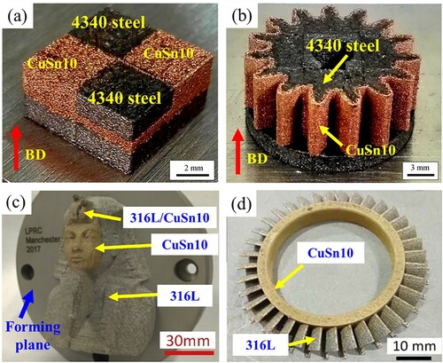
Theoretically, the multi-material structures with the intralayer printing can achieve predefined materials at desired positions within one part, thus being more compatible for multifunctional complex parts (e.g. electronic circuit, multi-material heat exchanger, and micro-nuclear power generation equipment). (a) and (b) exhibit CuSn10/4340 steel multi-material structures with the intralayer printing by LPBF (Wu et al. Citation2019a). The CuSn10 and 4340 steel powders can be delivered and printed not only in different layers but also in different zones of a single layer. The dimensional error in the material distribution was less than 0.1 mm, indicating a high printing accuracy of the CuSn10/4340 steel multi-material structures ((a)). (b) shows a printed CuSn10/4340 gear part, in which the outer contour (width of 0.5 mm) and interior was printed CuSn10 and 4340 steel, respectively. The printed gear simultaneously achieved the high mechanical strength and excellent wear resistance. Similar explorations on the printing of CuSn10/316L multi-material structures via LPBF were conducted (Wei et al. Citation2018; Wei, Sun et al. Citation2019). (c) shows the Sphinx part printed from CuSn10 and 316L SS, and CuSn10 was only used to print the human face of the part (Wei et al. Citation2018). (d) displays a turbine disk consisting of a CuSn10 ring and 316L blades (Wei, Sun et al. Citation2019). At the root of the blades, the material was gradually changed from 316L to CuSn10.
Figure 3. Metal/metal multi-material structures with the intralayer printing via LPBF: (a) a CuSn10/4340 block part, (b) a CuSn10/4340 gear part (Wu et al. Citation2019a), (c) a multiple colour, multi-material statue of the Sphinx (Wei et al. Citation2018), and (d) a CuSn10/316L turbine disk (Wei, Sun et al. Citation2019).
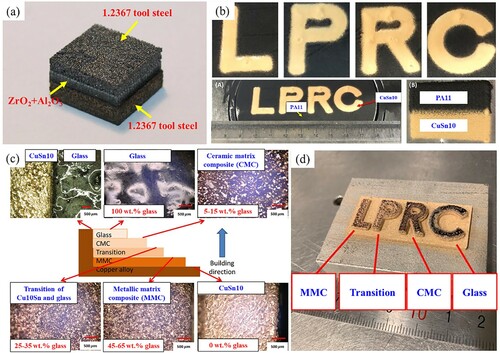
shows the metal/ceramic, metal/polymer, and metal/glass multi-material structures printed by LPBF. For the metal/ceramic multi-material structures, the printability of a 1.2367 tool steel/ZrO2/Al2O3 sandwich-like configuration was investigated (Koopmann, Voigt, and Niendorf Citation2019). The configuration comprised a tool steel porous structure and bulk at the top and bottom, respectively, as well as a ZrO2 + Al2O3 interlayer in between ((a)). They obtained an adhesion strength of 22 MPa between the 1.2367 tool steel porous structure and the ZrO2 + Al2O3 interlayer. For the metal/polymer multi-material structures, Chueh, Zhang et al. (Citation2020) investigated the printing of hybrid CuSn10/PA11 parts through a proprietary multi-material LPBF system ((b)). The results indicated a ‘proper distance’ maintained between CuSn10 and PA11, reducing the ‘balling’ caused by the carbon residue attached to the CuSn10 surface. For the metal/glass multi-material structures, Zhang et al. (Citation2020) printed an FGM part with composition variation from a copper alloy to a soda-lime glass using a proprietary nozzle-based multi-material LPBF system, which consisted of glass, ceramic matrix composite (CMC), transition, metallic matrix composite (MMC), and copper regions ((c) and (d)). A discrete interface was observed at CMC and MMC sides without oxidation transition layers in between, and the FGM part obtained a gradual transition from ductility at the metal side to brittleness at the glass side.
Figure 4. Metal/metalloid multi-material structures printed by LPBF: (a) 1.2367 tool steel/ZrO2+Al2O3 (Koopmann, Voigt, and Niendorf Citation2019), (b) CuSn10/PA11 (Chueh, Zhang et al. Citation2020), and (c, d) CuSn10/soda-lime glass (Zhang et al. Citation2020).
2.2. Interfacial microstructure
The microstructure of the interface between dissimilar materials has an important influence on the interfacial mechanical properties of LPBF-printed multi-material structures. Different interfacial microstructure could be formed in different multi-material types. As for the metal/metal multi-material structures, materials exhibit similar atomic bonds, and physical and chemical properties (melting temperature, thermal expansion coefficient, thermal conductivity, element composition, etc.). Therefore, a fusion region is usually generated at the multi-material interface where a composition gradient variation exists, contributing to a strong metallurgical bonding between dissimilar materials.
As shown in (a), a fusion region with a width of 550 μm was generated at the interface of 316L/CuSn10 multi-material structures, and the amount of Fe and Cu elements gradually varied in the fusion region (Chen, Yang et al. Citation2019). (b) shows a similar fusion region with an obvious dark feature at the interface of 316L/C52400 multi-material structures (Bai et al. Citation2020). (c) presents an inter-diffused region with a thickness up to 120 μm at the interface of LPBF-printed 300 maraging steel/304 SS multi-material structures (Tan, Wang et al. Citation2021). The tensile results showed that the 300 maraging steel was strongly bonded with the 304 SS, because all the fractures were located on the 304 SS side and far away from the interface. The circular flow features caused by intensive Marangoni convection can be observed in the melt pools at the interface, indicating that strong element diffusion of dissimilar materials occurred at the interface.
Figure 5. Interfacial microstructure of various combinations of dissimilar multi-material types: (a) 316L/CuSn10 (Chen, Yang et al. Citation2019), (b) 316L/C52400 (Bai et al. Citation2020), (c) 300 maraging steel/304 SS (Tan, Wang et al. Citation2021), (d) 316L/soda-lime glass (Zhang, Wei et al. Citation2019), (e) 1.2367 tool steel/ZrO2+Al2O3 (Koopmann, Voigt, and Niendorf Citation2019), and (f, g) CuSn10/PA11 (Chueh, Zhang et al. Citation2020).
However, if the materials exhibit great dissimilar atomic bonds, and physical and chemical properties, such as the metal/ceramic, metal/polymer, and metal/glass, a distinct boundary could be generated at their interface instead of the fusion region ((d–g)). Their bonding strength is mainly depended on the mechanical interlocking structures (Chueh, Zhang et al. Citation2020; Koopmann, Voigt, and Niendorf Citation2019; Zhang, Wei et al. Citation2019). (e) and (f) display the irregular interfaces of the steel/ceramic and copper/polymer multi-material structures, respectively, which can improve the bonding strength between the dissimilar materials through a mechanical interlocking structure. A rough surface of LPBF-printed parts is generally obtained due to the powder adhesion or irregularly shaped melt tracks, which contributes to the formation of mechanical interlocking structures at the interfaces. For example, the melted PA11 could better penetrate into CuSn10 and attach along the rough side surface of CuSn10 during laser scanning, resulting in strong adhesion of PA11 onto CuSn10 (Chueh, Zhang et al. Citation2020).
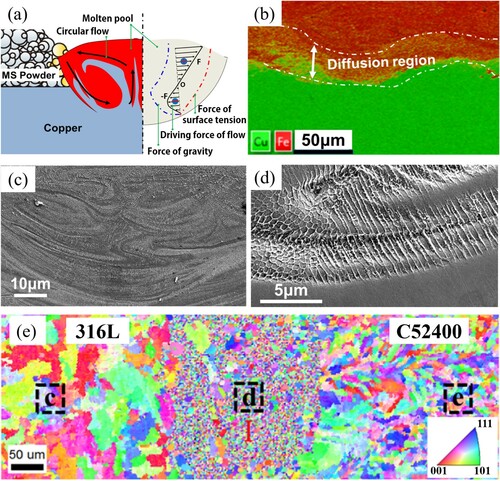
In the metal/metal multi-material parts, their unique microstructure features (acicular solidification microstructure, refined grains, etc.) could be beneficial to strengthening the interfacial bonding. Tan et al. (Citation2018) found that an element diffusion region was easily formed at the interface of grade 300 maraging steel/T2 copper multi-material structures along the Z-axis direction due to the Marangoni effect and the surface tension gradient of the melt pool at the interface ((a) and (b)). The circulating flow in the melt pool caused by the Marangoni effect can be observed as shown in (c). The temperature gradient at the solid–liquid interface G and the growth rate R can determine the morphology and size of the microstructure during solidification. The growth direction of the microstructure was parallel to the maximal temperature gradient. Some acicular grains of steel penetrated into the copper after solidification, acting as ‘reinforcing ribs’ at the interface and strengthening the interfacial bonding ((d)). In addition, Bai et al. (Citation2020) observed that the grains of the interface area were smaller than the grains of each material in a 316L/C52400 copper multi-material part, which could contribute to the hardening of the interface and the suppression of cracks, as shown in (e). The results showed that the 316L part was first printed via LPBF, followed by the printing of C52400 copper onto 316L. With a higher melting point, the pre-solidified 316L grains could provide cores for the subsequent growth of copper grains. The melt pool flow and Rayleigh-Taylor instability also played an important role in grain refinement at the 316L/C52400 copper interface.
Figure 6. Unique microstructure characteristics of multi-material structures along the build direction: (a-d) grade 300 maraging steel/T2 copper (Tan et al. Citation2018), and (e) 316L/C52400 copper (Bai et al. Citation2020).
2.3. Interfacial defects
The achievement of a porosity-free and crack-free interface with strong bonding is the most critical in the fabrication of multi-material structures through LPBF using dissimilar materials. Interfacial defects are critical challenges in multi-material LPBF. These defects include cracks, pores, delamination, and unmelted powder particles, as listed in . Cracks could occur in the fusion region because of the mismatch in thermal properties (thermal expansion coefficient, thermal conductivity, etc.) between dissimilar materials. Liu et al. (Citation2014) prepared the 316L/C18400 multi-material structures with LPBF, and found that cracks and pores were generated at the interface although a good metallurgical bonding was formed between steel and copper ((a)). Chen, Yang et al. (Citation2019) found numerous dendritic cracks at the 316L/CuSn10 interface ((b)). The residual stress caused by the high temperature gradients in LPBF could be concentrated on the 316L side because of the lower coefficient of thermal expansion of 316L compared to CuSn10. The 316L side was more prone to be a barrier restricting the expansion of the CuSn10 side, which could be torn by the CuSn10 side, and thus cracks were produced at the interface. (c) and (d) show the existence of cracks in the heat affected zone (HAZ) of 316L/soda-lime glass multi-material structures, resulting from the difference in the thermal expansion coefficient (Zhang, Wei et al. Citation2019). In addition, the initiation of cracks is caused by the formation of intermetallic brittleness phases generated during LPBF in material systems such as Al-Ti (Tomashchuk et al. Citation2015) and Fe-Ti (Bobbio et al. Citation2017). Moreover, the liquid metal embrittlement could induce cracks at the interface between stainless steel and copper, since the solid stainless steel could lose its ductility and becomes brittle when it contacts the liquefied copper (Wei, Zhang et al. Citation2020).
Figure 7. Interfacial defects in various multi-material structures: (a) 316L/C18400 (Liu et al. Citation2014), (b) 316L/CuSn10 (Chen, Yang et al. Citation2019), (c, d) 316L/soda-lime glass (Zhang, Wei et al. Citation2019), (e) AlSi10Mg/C18400 (Sing et al. Citation2015), (f) 1.2367 tool steel/ ZrO2+Al2O3 (Koopmann, Voigt, and Niendorf Citation2019).
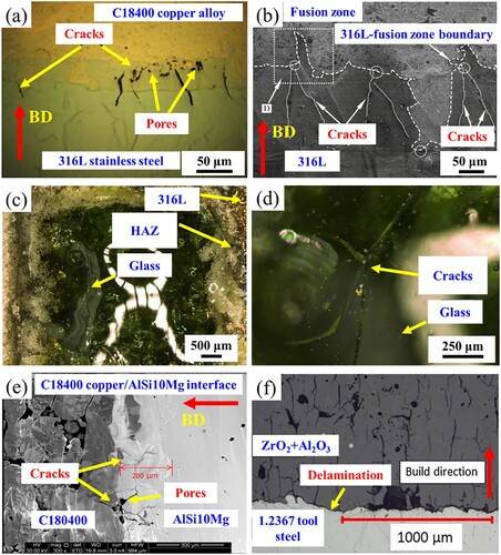
Table 2. Interfacial defects in LPBF-printed multi-material structures.
Pore formation may be occurred at the interface because of the insufficient laser energy density. Due to the high reflectivity and thermal conductivity of copper, the copper powder in the fusion region could not be totally melted, resulting in the formation of pores. Sing et al. (Citation2015) observed both cracks and pores at the interface of AlSi10Mg/C18400 multi-material structures, where macro pores were generated at the copper side ((e)). A higher laser energy density could be an effective way to eliminate the pores caused by insufficiently melting. However, the excessive laser energy density could lead to keyholes at the interface (Demir and Previtali Citation2017).
Delamination defect is often caused by insufficient metallurgical fusion at the interface and resultant poor bonding strength. (f) shows the delamination existing in a steel/ceramic multi-material part printed by Koopmann, Voigt, and Niendorf (Citation2019). Previous studies demonstrated that the bonding strength of the metal/ceramic interface depended on the mechanical interlocking structures, which could be influenced by the chemical bonding between the metal oxide layer and ceramic (Dikova, Vasilev, and Dolgov Citation2019; Wang, Gu et al. Citation2020). Since different atomic bonds of metal/ceramic, a mechanical interlocking structure is beneficial to increase the bonding strength. Chemical bonding is an important factor in determining the formation of mechanical interlocking structures between metals and ceramics, which can be influenced by the composition of metals and the formation of oxide layers on the metal surface. Chang et al. (Citation2016) found that the presence of the oxide layer could promote metal-ceramic bonds, which could provide a rough surface structure and promote the mechanical interlocking of metals and ceramics. The tensile results showed that the pathway of fracture remained within the ceramics, indicating that the bonding force between the alloy and ceramic was larger than the cohesive force of the ceramic. Moreover, the mismatch in thermal expansion coefficients between metals and ceramics could lead to higher interlayer stress and weaker bonding strength (Özcan Citation2003).
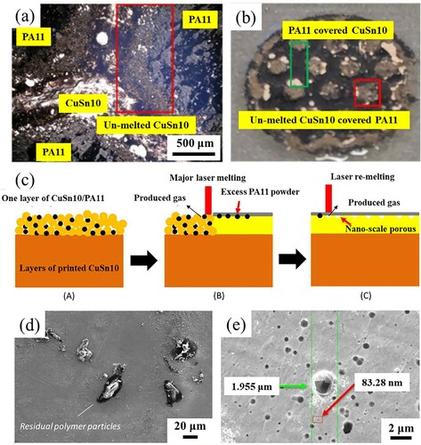
Unmelted powder particles usually exist at the interface of metal/metalloid multi-material structures due to the lack of fusion, which is detrimental to interface bonding. In metal/ceramic, metal/glass and metal/polymer multi-material structures, dissimilar materials possess different melting behaviours under the same laser energy input because of the huge differences in material melting temperature and laser absorbance. Wei, Chueh et al. (Citation2019) found that unmelted SiC powder particles were embedded in the 316L due to the higher melting temperature of SiC (up to 2730°C). Zhang et al. (Citation2020) found unmelted glass powder particles at the interface of CuSn10/soda-lime glass multi-material samples, because of the lower absorption of laser energy and higher transmission (up to 80%) for soda-lime glass. Chueh, Zhang et al. (Citation2020) also observed the unmelted CuSn10 powder particles in CuSn10/PA11 multi-material samples ((a) and (b)), and illustrated that the different melting temperature between CuSn10 and PA11 brought difficulties in the optimisation of laser energy input. In addition, when printing the Cu10Sn/PA11 mixed powder, the thermal pyrolysis of residual polymer particles on the melted CuSn10 surface during laser scanning resulted in nano-scale gas pores ((c–e)). Therefore, excessive and insufficient laser energy input could lead to evaporation of the polymer substrate and poor bonding strength caused by incomplete melting of the metal, respectively.
Figure 8. Interfacial defects in the LPBF-printed CuSn10/PA11 multi-material parts: (a, b) un-melted CuSn10 powder, (c) the illustration of laser melting and re-melting CuSn10/PA11 powder mixture, (d) residual polymer particles on the melted CuSn10 surface, and (e) SEM images of the surfaces of CuSn10 samples treated with laser re-melting (Chueh, Zhang et al. Citation2020).
2.4. Interfacial bonding strengthening methods
The mechanisms of defect formation at the interface of multi-material structures can be attributed to the mismatch in thermal properties with the materials and non-optimised printing process parameters in the LPBF process. A comprehensive understanding of the LPBF process is crucial to controlling the quality of multi-material structures. The microstructure, residual stress and thermal history are profoundly affected by the process parameters in LPBF (e.g. laser power, scanning speed, hatch space, layer thickness, and scanning strategy) (Liu et al. Citation2022). The process parameters adopted at the interface of multi-material structures should be carefully selected; otherwise, they can result in defects and weaken the interfacial bonding strength. Efforts have been made to achieve effective methods to suppress interfacial defects, including the optimisation of process parameters, the avoidance of material mutations, and the design of the interface (Chueh, Wei et al. Citation2020; Scaramuccia et al. Citation2020; Tey et al. Citation2020).
The process parameters have a significant influence on the properties (bonding strength, hardness, etc.) of the interface of multi-material structures (Chen, Yang et al. Citation2020). Line energy density (El) and volume energy density (Ev) are commonly used to quantify the laser energy input to the interface, which can be expressed by
(1)
(1)
(2)
(2) where p is the laser power (W), v is the scan speed (mm/s), h is the hatch distance (mm), and t is the layer thickness (mm) (Sing and Yeong Citation2020). Excessive and insufficient energy densities can result in the formation of interfacial defects in multi-material LPBF (Khorasani et al. Citation2020; Zhao et al. Citation2017). For example, the dominant defects at the Fe/Al-12Si interface were large cracks caused by insufficient fusion or excessive melting (Demir and Previtali Citation2017). Moreover, a large number of pores were generated at the cross-section of TiB2/Ti6Al4 V multi-material due to inadequate laser energy density, but samples with few pore defects and good interfacial bonding were obtained when the laser energy density was increased (Wang et al. Citation2019). Some unmelted 316L spherical particles were embedded in the fully melted copper region because of the low laser energy density in the LPBF-printed 316L/CuSn10 multi-material structures (Wei, Sun et al. Citation2019). However, keyholes may form at the interface while adopting an excessive laser energy density (e.g. with high laser power), since the high laser power could transfer the thermal transition mode from conductive to keyhole mode (Khairallah et al. Citation2020).
It is not advisable to optimise LPBF process parameters for dissimilar materials or compositional gradient materials with complex structures through conventional numerous trial-to-error experiments. Machine learning has been increasingly used for the process parameter prediction of LPBF-printed structures (Gobert et al. Citation2018; Yuan et al. Citation2018), which can directly obtain an accurate relationship between the input element and the output target through the model training of the preliminary data (Qi et al. Citation2019). However, limited works of machine learning have been carried out in multi-material LPBF. Rankouhi et al. (Citation2021) predicted the process parameters that were suitable for 316L/Cu multi-material structures with composition gradients through machine learning, indicating the great potential of machine learning to optimise the process parameters of multi-material LPBF.
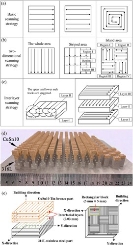
Since the scanning strategy is defined as the spatial moving pattern of the laser during the LPBF process, it varies by different scanning sequences, scanning directions, scanning vector lengths, scanning vector rotation angles, hatch spaces, etc. (Jia et al. Citation2021). Due to the rapid movement of laser during the LPBF process, scanning strategies can influence the heat flow direction, thermal gradient, and cooling rate inside the parts, which have a significant impact on the residual stress and microstructure. Consequently, an appropriate scanning strategy can be used to optimise the heat flow direction, thermal gradient, and cooling rate of the interface between dissimilar materials, thus reducing the residual stress and achieving the defect-free microstructure at the interface. Moreover, the pores at the interface can be significantly reduced by optimising the lap of the melt pool through the scanning strategy. (a–c) exhibit various scanning strategies applied to the LPBF process, including basic scanning strategies (e.g. single-direction scanning, dual-direction scanning, and spiral scanning), two-dimensional scanning strategies (e.g. plane scanning, strip scanning, and island scanning), and interlayer scanning strategies (e.g. interlayer staggered scanning and orthogonal scanning). A combination of scanning strategies can be flexibly adopted to print the interface of multi-material structures with reduced residual stress and the desired microstructure. Chen, Yang et al. (Citation2019) and Chen, Yang et al. (Citation2020) combined the inter-layer staggered scanning strategy and island scanning strategy to print the interface of 316L/CuSn10 multi-material structures ((d) and (e)), and the number of pores and the concentration of residual stress were reduced, resulting in a superior bonding strength at the interface.
Figure 9. (a) Basic scanning strategies, (b) two-dimensional scanning strategies, (c) interlayer scanning strategies, (d) CuSn10/316L multi-material structures (Chen, Yang et al. Citation2020), and (e) schematic of inter-layer staggered scanning strategy and island scanning strategy (Chen, Yang et al. Citation2019).
The remelting strategy is often used to print the interface of dissimilar materials with limited compatibility, which can remove oxide films and produce a clean solid–liquid interface at the atomic level (Sing, Huang et al. Citation2021). Moreover, it can provide extra energy input to promote the melting of powder. Koopmann, Voigt, and Niendorf (Citation2019) created a jagged surface between the steel layer and the ceramic layer through remelting, thereby significantly improving the bonding strength between the steel and ceramic ((e)), while delamination occurred without remelting ((f)). Similar observations were obtained in the remelting of the 316L surface when depositing the glass material on the 316L substrate (Zhang, Wei et al. Citation2019).
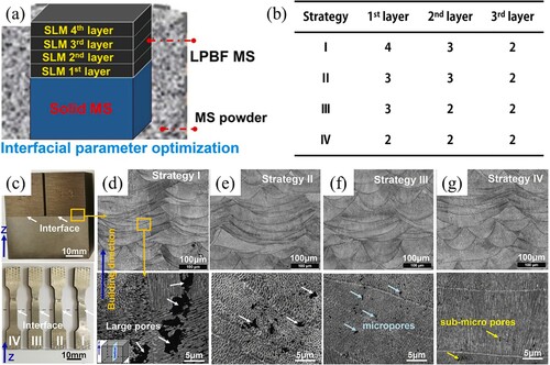
The number of remelted layers and the frequency to remelt each layer could influence the reliability of interface bonding. Tan, Wang et al. (Citation2021) studied the effect of four melting strategies on the microstructure at the interface of bulk grade 300 maraging steel (MS)/LPBF-printed MS ((a) and (b)). Four melting strategies (I to IV) for the first to third layers were carried out during LPBF of MS powder on the bulk MS. Specifically, the first to third layers were melted 4, 3 and 2 times respectively in strategy I, and accordingly, strategy II (3, 3 and 2 times), strategy III (3, 2 and 2 times) and strategy IV (2, 2 and 2 times) ((b)). (c) shows a typical bulk MS/LPBF-printed MS multi-material structure and its tensile samples. It can be observed that the fractures were located on the bulk MS side and far away from the bulk MS/LPBF-printed MS interface. They found that numerous pores appeared in the strategy I sample ((d)), which was considered excessive material evaporation due to the extremely high temperature of the melt pool after repeated melting. With a decrease in the remelting frequency, the number and size of pores in strategies II and III decreased ((e) and (f)), and only a few sub-micron pores could be observed in strategy IV ((g)). Therefore, suitable remelting for initial printing layers is beneficial to enhancing interfacial metallurgical bonding, and excessive remelting can cause pore defects.
Figure 10. Four melting strategies at the interface of bulk MS/LPBF-printed MS: (a) schematic illustrating the interface enhancement strategy, (b) four interface enhancement strategies, (c) multi-material specimens, (d) strategy I, (e) strategy II, (f) strategy III, and (g) strategy IV (Tan, Wang et al. Citation2021).
The methods to bond dissimilar materials at the interface of multi-material structures involve the direct bonding method (Bartolomeu et al. Citation2020; Chen, Yang et al. Citation2019; Tan et al. Citation2018), composition transition method (Demir and Previtali Citation2017; Wen et al. Citation2021; Zhang et al. Citation2020), and intermediate bonding layer method (Onuike and Bandyopadhyay Citation2018; Tey et al. Citation2020). The direct bonding method directly melts dissimilar materials, which enables the formation of a strong interface when the materials possess similar thermal properties. A compatible intermediate bonding layer between dissimilar materials is effective in eliminating the incompatibility of physical/chemical properties between dissimilar materials, which can create a strong and durable bonding interface. Moreover, the intermediate bonding layer method is often used to avoid the generation of detrimental phases between dissimilar materials. Ti/steel multi-material structures exhibit a favourable combination of corrosion resistance from titanium alloys and various properties (oxidation resistance, excellent hardness, good machinability, etc.) from relatively low-cost steels, which can potentially be applied in the nuclear power, chemical, and aerospace industries (Bobbio et al. Citation2017; Reichardt et al. Citation2016). However, detrimental Fe-Ti intermetallic compounds could form in the direct bond between steel and titanium. Tey et al. (Citation2020) obtained a Ti6Al4 V/Hovadur® K220 copper/316L SS multi-material part using LPBF, in which K220 copper was the intermediate bonding layer ((a)). Although the copper intermediate bonding layer could avoid the generation of Fe-Ti intermetallic compounds at the K220 copper/316L SS interface, they found that three detrimental phases existed at the interface of Ti6Al4 V/K220 copper ((b)), i.e. the L21 ordered phase, amorphous phase, and Ti2Cu, deteriorating the mechanical strength of the multi-material part. (c) shows the fracture paths at the interface of Ti6Al4 V/K220 copper. Interestingly, cracks initiated from the amorphous phase and then propagated within the β-Ti + Ti2Cu phase mixture. Finally, cracks can be diverted towards the K220 copper interlayer through a deflection around the α′-Ti phase. Therefore, the Ti6Al4 V/K220 copper samples achieved a high tensile strength by raising the interfacial volume fraction of the α′-Ti phase.
Figure 11. An LPBF-printed Ti6Al4V/Hovadur® K220 copper/316L SS multi-material part: (a) schematic of the part and tensile samples, (b) backscatter electron image and (c) illustration of fracture paths within the Ti6Al4V/K220 copper interface, (d) backscatter electron image and (e) inverse pole figure of the K220 copper/316L SS interface (Tey et al. Citation2020).
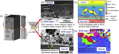
Moreover, the introduction of the intermediate layer will also have an impact on the microstructure of the interface, which in turn suppresses the formation of defects and enhances the interfacial bonding strength. In the K220 copper/316L SS interface, numerous micron-sized SS and copper globules can be found in the Cu-rich matrix and the SS bands, respectively ((d)), which were caused by the miscibility gap in the Cu-Fe system. (e) presents different microstructures at the interface of K220 copper/316L SS, indicating finer grains on the K220 copper side than on the SS side. This is because the liquid-phase-separated γ-Fe phase solidified first within the molten ϵ-Cu phase, which could be the low energy nucleation sites for the ϵ-Cu phase and lead to the formation of equiaxed grains. Interestingly, the equiaxed grains of the interface could suppress hot tearing and solidification cracking in susceptible materials and enhance the interfacial bonding strength (Martin et al. Citation2017).
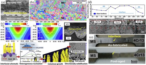
Recent research has demonstrated that in-situ synthesised interlayers can enhance the interfacial bonding strength of multi-material structures. Tan, Zhang et al. (Citation2020) proposed a novel approach to enhance the interfacial bonding of a 4Cr13 SS/MS multi-material part through the in-situ synthesis of a Cr-rich interlayer, as shown in (a). Two distinct grain morphologies (fine martensitic grains in LPBF-printed MS and coarse equiaxial grains in bulk SS) can be observed at the SS/MS interface ((b)). They found that the Marangoni effect promoted elemental migration and inter-diffusion at the interface through mass transfer, contributing to the in-situ formation of a Cr-rich interlayer, in which Cr-rich particles may act as a ‘seed’ for MS crystallization, and promote heterogeneous nucleation of maraging steel grains and subsequent epitaxial growth ((c)). Moreover, the segregation of the solute redistribution during solidification at the interface could also contribute to the in-situ interlayer formation. In the Fe-Cr system, the Cr element could diffuse from the solid into the liquid during solidification at a low temperature (Gui et al. Citation2020). Therefore, with a low laser energy and low temperature of melt pool, the Cr element could diffuse from the solid SS into the liquid MS pools spontaneously at the SS/MS interface. Consequently, the content of Cr element could increase at the interface, which was beneficial to the in-situ formation of a Cr-rich interlayer. Interestingly, they found that a Cr-rich in-situ interlayer can alleviate the strain of the interface to some extent, since the strain and distortion were unavailable to form at the interface. The results of hardness and tensile testing (including as-fabricated and post-aged samples) illustrated that the in-situ synthesised interlayer can enhance the interface bonding strength ((d) and (e)). The formation of the in-situ synthesised interlayer is beneficial to omitting the introduction of an additional compatible intermediate layer into the multi-material structures, which reduces the manufacturing lead time and avoids powder cross-contaminations.
Figure 12. In-situ synthesised interlayer formed in the LPBF-printed 4Cr13 SS/MS multi-material hybrid tooling: (a) the interfacial OM morphologies of SS/MS multi-material structures, (b) interfacial inverse pole figure, (c) the CFD simulation Marangoni convection in melt pool and microstructure evolution at the bonding interface, (d) the nano-hardness profile across the SS/MS interface, and (e) the standard tensile samples showing the location of fracture (Tan, Zhang et al. Citation2020).
For the composition transition method, a transition zone between dissimilar materials with a composition gradient can be created (Sun, Chueh, and Li Citation2020), which is more popularly termed as the FGM. The method enables gradient variations in the composition, microstructure and performance within multi-material structures and can avoid defect formation derived from the significant mutation in materials and stress concentration (Horn et al. Citation2019). Demir and Previtali (Citation2017) developed a multi-material LPBF platform for in-situ alloying of different elements and producing composite materials ((a)), which can realise a gradual change in the composition between two different materials. The platform consisted of three hoppers, including two upper hoppers to store different powders and one lower hopper to mix the powders. The vibrating plates and piezoelectric transducers in the platform were used to mix two materials with desired compositions. For example, a pure Fe/Al-12Si volumetric ratio of 55:45 was mixed to produce a composition transition zone between the pure Fe side and the Al-12Si side. In addition to metal/metal parts, Zhang et al. (Citation2020) used a proprietary nozzle-based multi-material LPBF system to obtain gradient materials with the composition variation from copper alloy to soda-lime glass, which can provide various ratios of metal/glass powders. However, unmelted powders could be formed when printing the mixed dissimilar materials, which could exhibit different melting behaviours due to their distinct thermal physical properties (melting point, laser absorptivity, and thermal conductivity, etc.). For example, Gu, Wei et al. (Citation2021) found that partially melted and un-melted Invar36 powders were embedded in the parts printed using Invar36/CuSn10 mixed powders, which can be attributed to the low laser absorptivity and high thermal conductivity of CuSn10.
Figure 13. Composition transition zones at the interface of multi-material structures: (a) the design and working principle of the powder feeder system, and the multi-material specimens of Fe/Al-12Si (Demir and Previtali Citation2017), and (b) schematic of a multi-material LPBF system with an adapted recoater for multi-material and characterisations of the printed IN718/316L specimens (Wits and Amsterdam Citation2021).
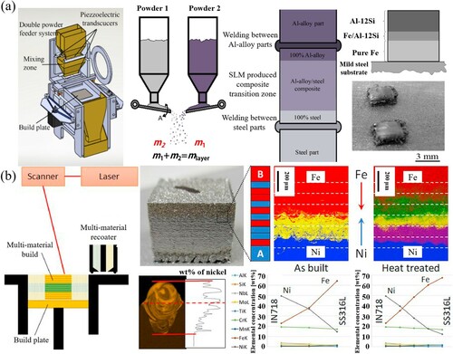
Wits and Amsterdam (Citation2021) presented an effective method to obtain the transition zone with a smooth material transition between IN718 and 316L. In (b), an adapted recoater that enabled multiple powder deposition in different layers was used to fabricate a gradual transition zone in IN718/316L multi-material structures. The transition zone was constructed by alternating the material deposition within 10 layers. After homogenisation heat treatment, the elemental diffusion was enhanced, resulting in a smooth material transition with a nearly linear change in elemental concentration. The results of the elemental diffusion in a single track showed an obvious solidification morphology caused by Marangoni convection, indicating great intermixing of Ni element within the melt pool. The unique advantage of this method is that additional powder mixture is not required.
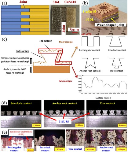
The design of the interface is another effective method to improve the bonding strength of multi-material structures. (a) presents a ‘finger-cross’ joint structure designed for the interface of 316L/CuSn10 multi-material structures (Wei et al. Citation2018). The enhancement of the interface bonding was attributed from the introduction of mechanical interlocking structures at the interface. Moreover, the increase of the contact area between dissimilar materials also facilitated the mixing of materials, which contributes to a gradual transition of dissimilar materials and the resultant reduction of defects derived from the material change at the interface. Similarly, a steel/copper gasket with strong metallurgical bonding was printed through designing a wave-shaped joint structure for the interface ((b)) (Wang et al. “Research Progress,” Citation2021), which can facilitate the element diffusion of dissimilar materials. Whereas, for metal/metalloid structures, since the atomic structure is different between metals and metalloids, the pre-created surface structure may be beneficial to enhance the joining strength by mechanical interlocking. Chueh, Wei et al. (Citation2020) designed three types of joint structures, i.e. interlock, anchor root, and tree contacts, for the interface of metal/polymer multi-material structures ((c)). First, the macroscopic mechanical interlocking structures of 316L SS were printed on a 316L substrate, and then the molten polymer was penetrated into the pre-printed 316L SS interlocking structures with a compressive pressure to improve the joining strength of the interfaces ((d)). The metal/polymer interface interlocking structures displayed a good combination of physical anchoring effect, resulting in a high bonding strength between the metal and the polymer ((e)).
Figure 14. Special joint designs of multi-material structures: (a) the ‘finger-cross’ joint (Wei et al. Citation2018), (b) the wave-shaped joint (Wang et al. “Research Progress,” Citation2021), and (c) designs of metal/polymer interface interlocking structures, (d) the pre-printed 316L SS interlocking structures, and (e) different metal/polymer interface interlocking structures (Chueh, Wei et al. Citation2020).
In summary, the interface characteristics are the priority in the multi-material structures printed by LPBF. The multi-material types for LPBF include metal/metal, metal/polymer, metal/glass, and metal/ceramic, which exhibit different mechanisms of interface formation and bonding. For example, the metal/metal multi-material structures obtain a fusion zone and unique microstructure (e.g. acicular solidification microstructure, refined grains) for a strong interfacial bonding; the metal/polymer, metal/glass, and metal/ceramic interfaces are bonded by the mechanical interlocking structures. Defects, such as cracks, pores, delamination, and unmelted powder particles, are often induced at the interface of LPBF-printed multi-material structures, which are detrimental to their mechanical properties.
Currently, the effective strengthening methods for interfacial bonding include the optimisation of process parameters at the interface, the introduction of intermediate bonding layers and the composition transition zone, and the design for interfacial shape and size. Among these methods, the composition transition method is most popular to reducing interfacial defects and stress concentration.
3. Critical technical issues in LPBF for multi-material structures
3.1. Equipment development
In the multi-material LPBF process, it is critical to deliver dissimilar powders to predetermined locations. The existing LPBF equipment is almost designed for the printing of a single material due to the limitation of powder delivery systems. Attempts have been made to print multi-material structures with material change along the build direction through replacing powders manually (Han et al. Citation2018). For example, Koopmann, Voigt, and Niendorf (Citation2019) printed a substrate using steel powder and then replaced the steel powder with ceramic powder in a single printing process to fabricate a steel/ceramic multi-material part. However, this method could significantly increase labour work, lead time, and material cost. The modification of the powder delivery system of original LPBF equipment is most effective to achieve customised changes in the physical location of dissimilar powder.
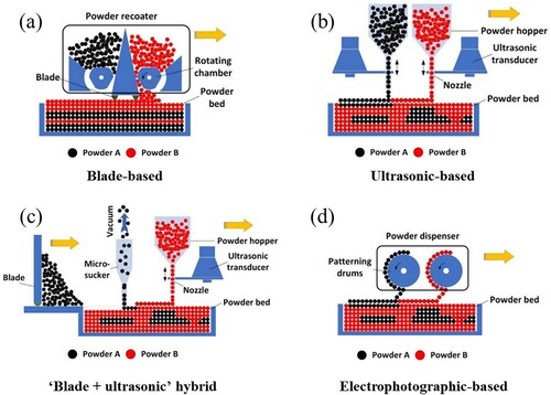
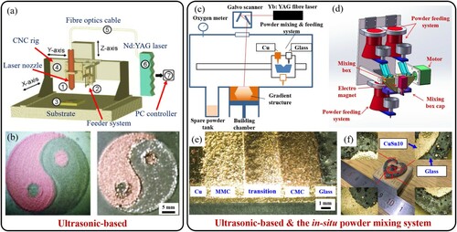
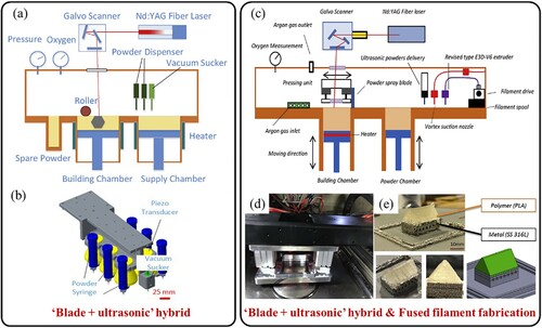
Wei and Li (Citation2021) classified modified powder delivery systems into blade-based, ultrasonic-based, ‘blade + ultrasonic’ hybrid, and electrophotographic-based powder spreading methods. The blade-based system can deliver dissimilar materials in the build direction (Z), but it is challenging to deposit them in a printing layer along the horizontal (X/Y) direction (Chen, Yang et al. Citation2019; Sing et al. Citation2015) ((a)). The ultrasonic-based system can dispense multi-material dry powder particles with different geometrical patterns to the powder bed by using ultrasonic wave vibration (Al-Jamal, Hinduja, and Li Citation2008), which has low material distribution efficiency ((b)). The ‘blade + ultrasonic’ hybrid powder spreading system utilises a powder blade to improve the powder deposition efficiency of ultrasonic-assisted LPBF (Wei et al. Citation2018) ((c)). The electrophotographic-based system can attract the powder particles onto a cylindrical mesh by using a point-by-point controlled micro-airflow, and then the powder particles are blown off the mesh and deposited on the powder bed to form a design pattern (Rafiee, Farahani, and Therriault Citation2020) ((d)).
Figure 15. Different modified powder feeding systems to print multi-material structures via LPBF: (a) blade-based, (b) ultrasonic-based, (c) ‘blade + ultrasonic’ hybrid, and (d) electrophotographic-based (Wei and Li Citation2021).
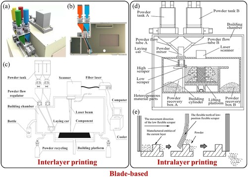
Based on the blade-based method, Demir and Previtali (Citation2017) designed a dual powder feeder system to modify their existing LPBF equipment, enabling the direct fabrication of multi-material structures with material variation along the Z-axis (interlayer distribution). (a–c) display the model and schematic illustration of a four-hopper powder feeding system in multi-material LPBF equipment (Chen, Yang et al. Citation2019). The four powder hoppers were installed on a laying car, and each of them had a switch to control the interlayer distributions of the four kinds of powder. The system has the capability to feasibly define specific process parameters for each printing layer of parts, which facilitates precise optimisation of energy density and suppression of defects at the interface.
Figure 16. Schematic diagrams of the multi-material LPBF equipment based on the blade-based method: (a–c) a four-hopper powder feeding system that can only realise the printing of interlayer multi-materials (Chen, Yang et al. Citation2019), (d) a flexible powder spreading system with the intralayer printing method, and (e) the powder removal mechanism (Wu et al. Citation2019b).
Furthermore, it is still challenging to realise the simultaneous distribution of dissimilar materials with the intralayer printing. The capability of printing different materials in the same layer and across different layers is crucial to obtaining multi-material products via LPBF (Stichel et al. Citation2016; Wei, Sun et al. Citation2019). Research has reported the combination of novel powder feeding methods and recycling methods. Wu et al. (Citation2019b) developed a novel LPBF machine for multi-material structures based on the blade-based method, as schematised in (d). Specifically, a new method based on a quantitative powder feeding through multiple hoppers and flexible cleaning was proposed to supply, spread and recycle dissimilar powders. For the multi-material structures with intralayer printing, a flexible scraper was used to remove unmelted powder after the printing of one layer ((e)). Then, dissimilar powders were delivered through the different hoppers and spread to fill in the vacant regions of the printable layer for printing. Nevertheless, slight material cross-contamination occurred in the printed multi-material structures, since it is difficult to clean up the residual powder outside the printing region in each powder layer.
Ultrasonic vibration has been demonstrated for the selective deposition of different powder materials (Al-Jamal, Hinduja, and Li Citation2008; Chianrabutra, Mellor, and Yang Citation2014). The prototype multi-material LPBF equipment with an ultrasonic-based powder deposition system is shown in (a) (Al-Jamal, Hinduja, and Li Citation2008). A Cu/H13 multi-material part with intralayer distribution was manufactured ((b)), which demonstrated great potential to multi-material structures with the intralayer printing by LPBF.
Figure 17. Schematic diagrams of the multi-material LPBF equipment based on the ultrasonic-based method: (a) the first prototype multi-material LPBF equipment with an ultrasonic-based powder deposition system (Al-Jamal, Hinduja, and Li Citation2008), (b) a Cu/H13 multi-material part with intralayer distribution, (c) the addition of an in-situ powder mixing system, (d) design of the in-situ powder mixing system, (e) the surface of the printed gradient CuSn10/soda-lime glass sample, and (f) a printed dual-heart ring prototype (Zhang et al. Citation2020).
Based on the ultrasonic-based method, Zhang et al. (Citation2020) added an in-situ powder mixing system to develop a novel multi-material LPBF machine to accurately change different proportions of mixed powder in the X/Y/Z direction ((c)). Specifically, CuSn10/soda-lime glass multi-material structures with a compositional gradient zone were printed using the modified machine. CuSn10 and soda-lime glass powders were mixed by the in-situ mixing system with different ratios, and then dispensed by an ultrasonic vibration feeding system. There were three sub vibration feeding systems in the in-situ powder mixing system, and two upper vibration feeding systems could dispense two different types of powders into the lower mixing box with constant powder flow rates ((d)). (e) shows the CuSn10/soda-lime glass gradient structure printed by the equipment, which contains a composition variation from CuSn10 to soda-lime glass including the areas of MMC, transition phase, and CMC. (f) displays a printed CuSn10/soda-lime glass multi-material dual-heart ring. However, the multi-material LPBF equipment based on the ultrasonic-based method are characterised by low efficiency.
To improve the efficiency of powder deposition, the ultrasonic-based powder deposition system and the powder blade-assisted LPBF system has been integrated to deliver different powders, which was termed as the ‘blade + ultrasonic’ hybrid method. (a) and (b) show the multi-material LPBF equipment that integrated the traditional powder spreading system with a selective material removing system through the point-by-point micro-vacuum and point-by-point ultrasonic powder distribution, respectively (Wei et al. Citation2018; Wei, Sun et al. Citation2019). In the equipment, the powder material constituting the main part of the component was spread through the traditional powder spreading system, and then the point-by-point micro-vacuum system was used to remove the unmelted powder in pre-defined local areas. Finally, the other powder materials were delivered into the vacancy areas through ultrasonic powder feeding nozzles. However, the powder delivered by ultrasonic powder feeding nozzles was not compacted, which resulted in a low compaction density of the powder in these areas and the resultant formation of cracks and pores during the printing process. An additional plate driven by a pneumatic cylinder was developed to compress the loose powder dispensed from the ultrasonic nozzle, which can significantly increase the relative density of parts (Wei, Gu et al. Citation2019).
Figure 18. Schematic diagrams of multi-material LPBF based on the ‘blade + ultrasonic’ hybrid method: (a) the equipment integrated the ultrasonic-based powder deposition system and the powder blade-assisted system (Wei et al. Citation2018), (b) the details of ultrasonic-based powder deposition system (Wei, Sun et al. Citation2019), (c) the addition of an FFF system, (d) the pressurisation system, and (e) a printed 316L/PLA multi-material mini house (Chueh, Wei et al. Citation2020).
The ‘blade + ultrasonic’ hybrid method provides the possibility to combine other polymer AM processes (e.g. fused filament fabrication, FFF) to obtain mechanical interlock structures in the metal/polymer multi-material parts. Chueh, Wei et al. (Citation2020) integrated an FFF system and a pressurisation system into the original multi-material LPBF equipment to enable the fabrication of metal/polymer multi-material structures. (c) and (d) show the schematic of the modified equipment and the pressurisation system, respectively. After printing the metallic interlocking structures (316L) in the LPBF process, the residual loose powder inside the metallic interlocking structures was removed by a vacuum sucker, and the metallic interlocking structures were filled up by the polymer in the FFF process. The pressurisation system was used to compress the melted polymer (PLA) into the metallic interlocking structures to form a mechanical interlock structure between the metal and polymer, as shown in (e).
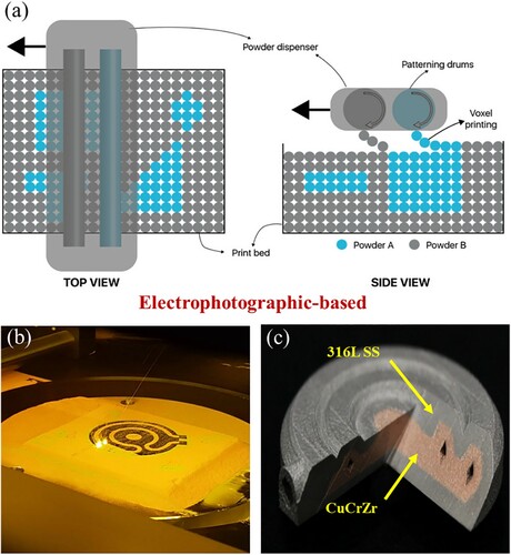
Based on the electrophotographic-based method, Aerosint SA company (Belgium) has developed a multi-material printing machine based on LPBF that can print polymer, ceramics and metal powders with relatively high efficiency (Rafiee, Farahani, and Therriault Citation2020) ((a)). For instance, a 316L SS/CuCrZr multi-material part with an intralayer distribution of dissimilar materials can be printed based on the selective deposition of voxels of powder ((b) and (c)). The powder dispenser is the key component of the equipment, which uses two drum-shaped powder feeding systems to realise the distribution of two dissimilar materials at any zones. The increase in the number of the drum-shaped powder feeding system enables the printing of increased material types. In addition, the non-contact powder spreading of the system can print brittle materials without shear and friction on them, and thus prevent partial warping of printed parts.
Figure 19. Schematic diagrams of the multi-material LPBF equipment based on the electrophotographic-based method developed by Aerosint SA: (a) schematic of selective powder recoating, (b) the printing process, and (c) a printed 316L SS/CuCrZr multi-material part (Rafiee, Farahani, and Therriault Citation2020).
Although various multi-material LPBF equipment have been developed for printing multifunctional and geometrically complex parts, low efficiency and powder cross-contamination are still the critical challenges for the equipment. Highly efficient and high-quality powder feeder systems for the flexible combination and precise distribution of dissimilar materials are still prerequisites for industrial applications.
3.2. Data preparation
One of the prerequisites for the LPBF processing of multi-material structures is creating their 3D models (Zhang and Joshi Citation2017). Currently, most of the mainstream 3D models only express the geometric information of a part without its material information due to the limitation of commercial software available, which could hinder the printing of multi-material structures. presents a data preparation method of multi-materials, which should be processed through model segmentation, definition and combination to obtain multi-material structures with a complex shape (Wei et al. Citation2018; Wu et al. Citation2019b). Nevertheless, this method requires a complicated manual process that is not conducive to mass production and extensive industrial applications. Therefore, a type of data interface file that can simultaneously express the geometric and material information and connect with the manufacturing process is critical to the integration of the design and manufacturing of multi-material structures (Loh et al. Citation2018; Muller, Mognol, and Hascoet Citation2012).
Figure 20. Manual data preparation procedures for the LPBF printing of multi-material structures (Wei et al. Citation2018).
Currently, the generally accepted data formats in AM include STL (standard tesselation language), OBJ (object file format), AMF (additive manufacturing format) and PLY (polygon file format) files (Loh et al. Citation2018). The STL file is the most widely used data format and has become a standardised input file for commercial AM equipment, but it cannot express the material information (Bonnard, Hascoët, and Mognol Citation2019; Li et al. Citation2020). STL 2.0 was developed to express the material information of each area in the part (Hiller and Lipson Citation2009). The OBJ file can express colour information, but it is still unable to express material information. The AMF file is a multi-material AM data format proposed by the American Society for Testing and Materials (ASTM) for standardisation, which can express both geometric and material information but occupy a large storage space (Liu and Jing Citation2019). The AMF file is still in the open-sharing stage and immature to be applied to multi-material structures (Shi, Yang, and Wang Citation2017). The PLY file uses a polygonal mesh to express the surface information of a part, such as texture and colour. However, the PLY file is unavailable when a part contains different material properties (Zhu and Wang Citation2017).
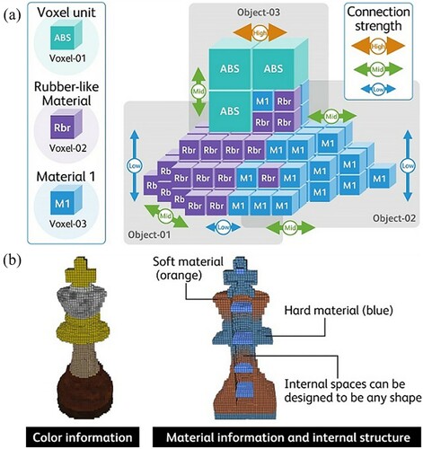
Some potential file formats (such as fabricatable voxel, FAV; simple voxels, SVX; and 3D manufacturing format, 3MF) can be used in LPBF-printed multi-material structures, which can carry information about the material gradient and micro-scale physical properties beyond a fixed geometric description (Loh et al. Citation2018). The FAV format comprises the digital information of the exterior and interior of an object through voxels, including its colours, materials, and connection strength, as shown in (FUJIFILM Business Citation2017). SVX is a voxel transmittal format to carry voxel-based models for AM, which can contain information on material allocation, density, RGB colour, etc (Shapeways Citation2014). In addition, 3MF, a new file format, has been developed to define the process data in manufacturing processes and describe the intrinsic and extrinsic information of a model. However, the 3MF file does not support solid modelling with higher-order representations such as B-Rep (boundary representation), NURBS (non-uniform rational B-splines) and STEP (standard for the exchange of product model data) (Shi, Yang, and Wang Citation2017).
Figure 21. (a) Conceptual diagram showing voxels arranged three-dimensionally, and (b) the FAV format can retain information on internal structure, colour, and material (FUJIFILM Business Citation2017).
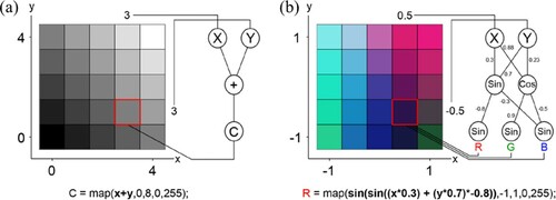
Multi-material structures for LPBF require a new approach of computational modelling that can not only contain geometric information but also specify and manage the material information for local composition control (Loh et al. Citation2018). The new approach of computational modelling should be able to control the proportion and directionality of the materials in 3D space. Michalatos and Payne (Citation2013) demonstrated a way that uses volumetric gradient patterns to control a voxel-based model, which can vary the material information of 3D printed structures in volume by defining the property of each voxel by a function of its Cartesian (x, y, z) coordinates. Richards and Amos (Citation2014) proposed a computational approach of using CPPN (Compositional Pattern Producing Network) encodings and a scalable algorithm using NEAT (Neuroevolution of Augmented Topologies) to embed multi-material information in multi-material parts through voxel-by-voxel descriptions by a function of its Cartesian (x, y, z) coordinates (). To reduce the amount of calculation in the conversion of the voxel model from a common geometric format (i.e. STL file) for multi-material structures, General (Citation2018) proposed an alternate design-supporting system to represent material-geometry-topology with a volumetric texture map. It allows modifications on voxel models and then compiled back into the texture description to change at different scales. Therefore, functional representation is an effective method to provide a viable way of describing multi-material physical objects with complex internal architectures.
Figure 22. (a) Simple gradient pattern generated by summing the X and Y coordinates of each pixel to generate a colour: C, and (b) CPPN generated pattern. The equation below (b) shows the calculation of the red value (Richards and Amos Citation2014).
3.3. Thermodynamic calculation and process simulation
It is critical to understand the compatibilities of material properties and predict the behaviours of the dissimilar materials (interfacial morphology, melt pool shape, microstructure evolution, etc.) in the multi-material LPBF process, and then rapidly screen material types and process parameters for multi-material structures. However, the compatibilities of material properties and the underlying physical behaviour in multi-material LPBF are complex scientific matter related to the thermodynamics and fluid dynamics of the melt pool, the phase transition, the thermodynamics of materials, etc. In addition, highly compatible materials may possess similar functions, resulting in the single function of a multi-material part, which may be unable to adapt to variable working environments. Currently, the optimisation of process parameters of interface is still mainly through numerous trial-to-error experiments, which can lead to long lead time and high cost (Chen, Yang et al. Citation2020).
The calculation of phase diagram (CALPHAD) is a useful thermodynamic calculation method that can be employed to determine the thermodynamic properties of multi-component structures (Wei and Li Citation2021). The CALPHAD method can establish a thermodynamic model based on the crystal structure of each component phase (gas phase, liquid phase, solid solution, compound, etc.). In multi-material structures, CALPHAD can provide critical information for accurately predicting the phase formation. Therefore, the compatibility of dissimilar materials can be evaluated through CALPHAD. The transition path from one material to another can also be designed based on the results of thermodynamic calculations through CALPHAD, which can avoid the generation of undesired phases.
Numerical simulation is an effective way to gain the insight of the underlying physical behaviour during the multi-material LPBF process (Yao et al. Citation2021). It is critical to understand the formation mechanisms of the interface microstructure in multi-material LPBF. However, current research on the microstructure simulation using phase-field modelling and cellular automata method is mainly developed for binary alloys or tertiary alloys (Tan, Sing, and Yeong Citation2020). In addition, a lack of physical properties of mixed materials is another barrier to obtain the accurate model of multi-material LPBF at the microscopic scales. Therefore, limited works have been carried out based on the microscopic methods. Mohanty and Hattel (Citation2017) developed a thermo-microstructural model for a steel/nickel multi-material structure to simulate nucleation and grain growth in LPBF process using a sequentially coupled 3D thermal model and a 2D cellular automata microstructure model. However, only a single melting track of steel was investigated, and the microstructure of multiple melting tracks in multi-material LPBF process was not discussed.
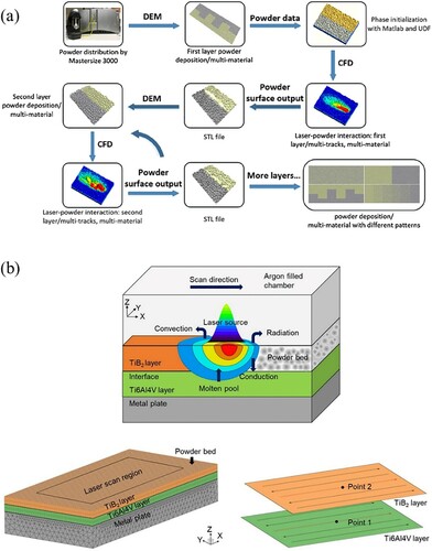
Gu et al. (Citation2020) developed an integrated modelling framework to predict melt pool development of multi-track, multi-layer and multi-material structures during the multi-material LPBF process on the mesoscopic scale ((a)). In this framework, various combinations of powder materials for multi-material structures can be explored prior to printing, which provides valuable insights on the design and optimisation of multi-material structures. Sun, Chueh, and Li (Citation2020) developed a computation fluid dynamic model at the mesoscale for simulating single-track multi-material LPBF melt pool behaviour. An inhomogeneous temperature distribution was observed in melting the mixed IN718/CuSn10 powder because of the different thermal-physical properties (melting points, laser beam absorptivity, thermal conductivity, etc.) of dissimilar materials. The temperature of the melt pool decreased with increasing the CuSn10 content. In addition to metal/metal multi-material structures, Chen, Gu et al. (Citation2019) proposed a multi-layer finite element model to investigate the thermal behaviour of TiB2/Ti6Al4 V multi-material structures by LPBF, and the subsequent experiments proved the effectiveness of the model ((b)). Through the multi-layer finite element model to screen process parameters, an appropriate penetration depth of the TiB2 layer can be obtained at the interface to achieve sound interfacial bonding between TiB2 and Ti6Al4 V. In addition, machine learning and artificial intelligence can be used to supplement simulations to obtain multi-material structures with fewer defects and higher quality (Goh, Sing, and Yeong Citation2021; Meng, McWilliams et al. Citation2020).
Figure 23. (a) A framework for multi-track, multi-layer and multi-material LPBF modelling (Gu et al. Citation2020), and (b) schematic overview of the LPBF physical model for multi-material structures (Chen, Gu et al. Citation2019).
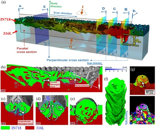
However, the evolution of the 3D morphology of the interface between dissimilar materials was not investigated in these simulation works. Recently, Yao et al. (Citation2021) developed a multi-physics model that combines micron-scale fluid dynamics with nanosecond-level thermal diffusion processes to examine the 3D morphology evolution of the interface between 316L and IN718 ((a)). They found that a ‘fish-scale’ morphology could be obtained when the aspect ratio of the melt pool at the interface was higher than 0.25 and lower than 0.55 ((b–f)). The ‘fish-scale’ morphology could contribute to the formation of mechanical interlocking structures and entangled curved grains at the interface ((f) and (g)), thus improving the interfacial bonding strength.
Figure 24. (a) Representative image of a single-track laser scan showing the cross sections used for various viewing directions, (b–e) simulation results of the flow characteristics within the melt pool from cross-sections A-A, B-B, C-C, and D-D, respectively. (f) ‘Fish-scale’ morphology of the interface, and (g) representative elemental distribution maps and microstructures along the cross-section E-E (Yao et al. Citation2021).
3.4. Powder cross-contamination and recycling
The development of LPBF equipment enables the printing of multi-material structures with dissimilar materials spatially distributed as desired. However, powder cross-contamination and recycling of different powders after printing are still critical issues to be addressed. On the one hand, the intrinsic characteristics of LPBF (e.g. based on the powder bed) bring the inevitable problem of powder cross-contamination during the printing of multi-material structures (Horn et al. Citation2019). It is necessary to clean up the powder in the unmelted region after printing one powder layer; otherwise, the mixture of dissimilar powders occurs to cause powder cross-contamination (Montazeri et al. Citation2018). This mixture may disrupt the fine material layout and change the function of multi-material structures (Gu et al. Citation2014; Tang et al. Citation2015), which is detrimental to the precise control of their performance. Thus, a cleaning system is critical for the multi-material LPBF equipment to effectively remove unscanned powders within a printed layer. Furthermore, the powder preset capability of the equipment is also required to achieve the precise preset of dissimilar powder. Wei et al. (Citation2018) and Wei, Sun et al. (Citation2019) used an ultrasonic transducer to achieve the precise powder presetting, including the spreading of dissimilar powders and powder removal through a vacuum sucker, which can reduce powder cross-contamination.
On the other hand, the recycling, separation and reuse of dissimilar powders should be considered for the multi-material LPBF equipment to reduce the material cost. If the mixed powders have significant differences in particle size, they can be separated by sieving (Chivel Citation2016); if the mixed powders have different magnetic properties, they can be separated by magnetic adsorption (Binder et al. Citation2018; Wu et al. Citation2019b); if the mixed powders obtain different densities, they can be separated by particle inertia (Ullrich Citation2013). Moreover, the multi-material LPBF equipment should avoid mixing raw powder during the printing process.
In summary, the critical technical issues in multi-material LPBF are focused on equipment development, data preparation, thermodynamic calculation and process simulation, and powder cross-contamination and recycling. Various multi-material LPBF equipment has been developed based on the modification of powder feeding systems, including blade-based, ultrasonic-based, ‘blade + ultrasonic’ hybrid, and electrophotographic-based. These developed LPBF equipment can construct the multi-material structures with the interlayer or intralayer printing, but all of them show low efficiency and powder cross-contamination.
There is still a lack of data formats to simultaneously express the geometric and material information of multi-material structures, which can be supplemented by introducing some potential file formats (such as FAV, SVX, and 3MF) and new approaches (such as the functional representation). The thermodynamic calculation (such as CALPHAD) and process simulation are effective to understanding the compatibilities of material properties, predicting the physical behaviours of the dissimilar materials in multi-material LPBF, and rapidly screening material types and process parameters for printing. However, limited works have been carried out on the microstructure simulation due to the lack of modelling methods for multi-material systems and physical properties of mixed materials. As for powder cross-contamination and recycling, the mixed dissimilar powders can be separated through sieving, magnetic adsorption, particle inertia from their significant differences in particle size, magnetic properties, and densities, respectively.
4. Potential applications
LPBF-printed multi-material parts with diversified functions/performance have great potential to work in harsh environments such as high temperature, high load, and high corrosion, in various applications of aerospace, nuclear energy, marine and offshore. In addition, multi-material AM has even demonstrated its advantages in the field of four-dimensional (4D) printing (Rafiee, Farahani, and Therriault Citation2020). For example, new smart materials with a specific shape variation can be obtained after heating through the layout design of dissimilar materials (e.g. shape memory alloys and non-shape memory alloys), as shown in (a) (Shi et al. Citation2020). Multi-material structures can also be applied in powertrain transfer systems. (b) presents a printed CuSn10/PA11 multi-material gear with a height of 3 mm, which demonstrated the capability of multi-material LPBF for the fabrication of metal/polymer components with complex structures (Chueh, Zhang et al. Citation2020). PA11 and CuSn10 were used to print the interior and exterior of the gear, respectively. The printed multi-material gear can potentially be applied in environments with insulation and force transmission required in the field of power transmission. (c) displays a printed copper/polymer turbine blade in which only the central of the blade was made of copper. The copper/polymer turbine blade can potentially be applied in dynamical systems driven by magnetism.
Figure 25. LPBF-printed multi-material parts with potential applications in 4D printing, powertrain transfer systems, and communication equipment: (a) smart multi-material structures of Ni20Mn6/Ni36 (Shi et al. Citation2020), (b) hybrid CuSn10/PA11 gear, (c) CuSn10/PA11 turbine blades, (d) a CuSn10/PA11 mobile phone back housing, and (e) a 316L SS/CuSn10/PA11 interlocking ring (Chueh, Zhang et al. Citation2020).
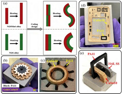
In the field of communication equipment, polymer components such as speakers, control modules and radiation/electrical insulators can be attached to the metallic electronic device housing. (d) shows a CuSn10/PA11 multi-material mobile phone back housing printed by LPBF, which may simplify the production of mobile phone back housing. (e) presents a 316 SS/CuSn10/PA11 multi-material interlocking ring, which consists of three dissimilar materials. In the sector of electronic circuits, the method of directly fabricating complex multi-material structures can be integrated with other AM processes to manufacture 3D complex electrical circuits (Li et al. Citation2016), thus enabling the printing of entire electrical devices directly. Moreover, multi-material LPBF can allow the construction of complex 3D metal circuits and ceramic package shapes with the desired materials at predefined locations for functionality or performance improvement (e.g. electrical conductivity, insulation performance, waterproof function, and seismic and compression resistance) (Gheisari et al. Citation2020; Raynaud et al. Citation2020; Sahasrabudhe and Bandyopadhyay Citation2016).
(a) shows a metal/glass multi-material decoration structure printed by LPBF (Zhang, Wei et al. Citation2019), which demonstrates the innovative feasibility of multi-material LPBF in the jewelry field. It can not only omit the subsequent inlay process but also directly fabricate complex structures with dissimilar material distributions (e.g. combining several types of precious metals). (b) shows a multi-material tubular heat exchanger of CuCrZr/316L with a complex curved structure manufactured by Aerosint SA company (Belgium) (Aerosint Citation2021). In the heat exchanger, the copper tube acts as one of the channels and is surrounded by the 316L channel. The LPBF processing of the multi-material heat exchanger is cost-effective compared to traditional welding methods. To combine the high-temperature performance of IN718 with the high ductility and low-cost characteristics of 316L SS, the multi-material heat exchangers have been manufactured by Wits and Amsterdam (Citation2021) ((c)).
Figure 26. LPBF-printed multi-material parts with potential applications in the field of jewelry and energy: (a) a CuSn10/glass pendant (Zhang, Wei et al. Citation2019), (b) the CuCrZr/316L multi-material heat exchanger (Aerosint Citation2021), and (c) IN718/SS316L multi-material heat exchanger (Wits and Amsterdam Citation2021).
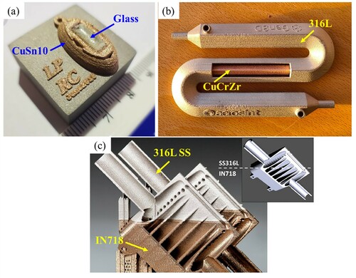
In the biomedical field, the LPBF processing of multi-material structures allows printed implants to achieve a fine multi-material layout to obtain various properties (e.g. biocompatibility, stiffness, abrasion resistance, corrosion resistance) required by human bones (Putra et al. Citation2020; Zhang and Attar Citation2016). (a) shows a printed NiTi/Ti6Al4 V multi-material hip implant (Bartolomeu et al. Citation2020). This multi-material hip implant comprises the Ti6Al4 V inner region with adequate mechanical strength and stiffness, and the NiTi outer region with a controlled volume expansion (shape memory activation) to promote a suitable bone-implant contact and induce bone ingrowth. Metal/polymer hybrid structures can also be applied for orthopedic applications. For example, metal implants with the function of local drug delivery are generally required to prevent infection after prosthetic joint replacement surgery. However, the drug release profile cannot be controlled by drug-loaded biodegradable polymer coating on implants (Manoj Kumar et al. Citation2017). Chueh, Wei et al. (Citation2020) developed a novel LPBF-printed metal/polymer implant with a controllable drug delivery profile. The polymer that could be loaded with antibiotics is biodegradable and embedded inside a metallic implant, as shown in (b). In addition, it is feasible to manufacture multi-material artificial teeth with a metal core and a ceramic shell through the LPBF process, which can achieve excellent mechanical performance and a higher compatibility with the human body (Wei et al. Citation2018).
Figure 27. LPBF-printed multi-material parts with potential applications in the biomedical field: (a) design concept of a NiTi/Ti6Al4V multi-material hip implant for LPBF (Bartolomeu et al. Citation2020), and (b) an LPBF-printed metal/polymer implant with a controllable drug delivery profile (Chueh, Wei et al. Citation2020).
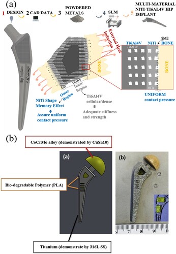
In the aerospace sector, the LPBF process can be used to fabricate multi-material parts that work in extremely harsh environments to achieve excellent environmental adaptability by configuring flexible material layouts in a cost-effective way (Meng, Zhang et al. Citation2020; Zhao et al. Citation2018). For instance, the National Aeronautics and Space Administration (NASA) has conducted a project called ‘Rapid Analysis and Manufacturing Propulsion Technology’ (Gradl et al. Citation2020), and one of the critical objectives of the project is the advancement of bimetallic and multi-metallic AM technologies. In the project, LPBF has been maturely applied to the fabrication of combustion chambers, and combined with other AM techniques (e.g. blown powder-directed energy deposition, BP-DED) to fabricate lightweight thrust chamber assemblies (). This indicates that multi-material LPBF technology can produce continuous cooling channels between the chamber and the nozzle, and reduce the weight of parts by configuring appropriate material layouts.
Figure 28. (a) An LPBF-printed GRCop chamber prepared for BP-DED, (b) a BP-DED process of coupled manufacturing demonstrator, and (c) a completed coupled BP-DED/LPBF bimetallic demonstrator (Gradl et al. Citation2020).
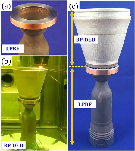
5. Conclusion and outlook
This review summarises the research progress on the multi-material structures (in particular dissimilar materials) printed via LPBF. The interface characteristics and strengthening methods of LPBF-printed multi-material structures, critical technical issues in multi-material LPBF, and potential applications are reviewed.
The main types of multi-material structures are available to LPBF include metal/metal, metal/polymer, metal/glass, and metal/ceramic. Among them, the metal/metal systems are most extensively investigated, including 316L/CuSn10, 316L/IN718, Ti6Al4 V/IN718, CuSn10/18Ni300, AlSi10Mg/C18400, etc. The interface formation and bonding mechanisms are different in different multi-material types. As for the metal/metal structures, a fusion zone and unique microstructure (e.g. acicular solidification microstructure, refined grains) can contribute to a strong interfacial bonding; the metal/polymer, metal/glass, and metal/ceramic structures are bonded by the mechanical interlocking structures. Defects (such as cracks, pores, delamination, and unmelted powder particles) are the critical challenges to the mechanical properties of LPBF-printed multi-material structures. The current effective methods to suppress interfacial defects and enhance the interfacial bonding include the optimisation of process parameters at the interface, the introduction of intermediate bonding layer and the composition transition zone, and the design for the interface.
The critical technical issues of the multi-material LPBF technology contain the development of powder feeding systems, data preparation, thermodynamic calculation and process simulation, and powder cross-contamination and recycling. Based on the modification of powder feeding systems (blade-based, ultrasonic-based, ‘blade + ultrasonic’ hybrid, and electrophotographic-based), various multi-material LPBF equipment has been developed to construct the structures with the interlayer or intralayer printing. However, low efficiency and powder cross-contamination are still the challenges for them. The lack of data formats to simultaneously express the geometric and material information of multi-material structures is another barrier for the multi-material LPBF, which could be solved by some potential file formats (such as FAV, SVX, and 3MF) and new approaches (such as the functional representation). The thermodynamic calculation and process simulation can help to understand the compatibilities of material properties, predict the physical behaviours of the dissimilar materials in multi-material LPBF, and rapidly screen material types and process parameters for printing. The mixed dissimilar powders can be separated to reduce powder contamination and recycling through sieving, magnetic adsorption, particle inertia from their significant differences in particle size, magnetic properties, and densities, respectively. LPBF-printed multi-material parts have great potential in the applications of 4D printing, electronic, jewelry, energy, biomedical, aerospace, etc. The hybrid manufacturing method combining multi-material LPBF with other AM methods (e.g. BP-DED) provides an effective method for high-efficiency production and application.
The perspectives regarding the future of multi-material LPBF are outlined as follows.
In multi-material LPBF, the mismatch of thermal properties and the formation of secondary phases (e.g. brittle intermetallics and carbides) can cause high residual stress and resultant delamination and cracks in the LPBF-printed multi-material structures. However, current commercial simulation software that can work on phase transformation prediction are usually designed for single-material printing, it is challenging to predict the formation of secondary phases and defects at the interface of multi-material structures. Therefore, the thermodynamic calculation and process simulations can be developed for multi-materials to understand the temperature gradient, thermal stress distribution, and solidification behaviours at the multi-material interface, and thus provide a theoretical guidance to enhance interfacial bonding strength and minimise defects.
Various multi-material types can be developed by LPBF to fulfil the increasing requirements on the multifunctionality of parts from industrial applications. Machine learning can be introduced to accelerate the development of new multi-material types for LPBF. A comprehensive database consisting of material properties (chemical composition, melting point, laser absorptivity, thermal conductivity, specific heat capacity, etc.), printing process parameters (laser power, scanning speed, layer thickness, hatch space, etc.), and printed multi-material part performance (strength, ductility, fatigue life, wear resistance, corrosion resistance, etc.) can be established for training machine learning models (Chen et al. Citation2021). The trained models can then be used to predict the part performance of new multi-material types. In addition, the intermediate temporal-level thermal dynamics and spatial-level structural evolutions during printing can be monitored through a high-fidelity characterisation method based on real-time monitoring techniques (e.g. the high-speed X-ray imaging). Thus, the thermal behaviours and structural formation between dissimilar materials in multi-material LPBF can be understood.
The design of the multi-material interface can be effective to the enhancement of the interfacial bonding strength. Continuous gradient transition zones and mechanical interlocking structures can be created at the interface of LPBF-printed multi-material structures. The influence of the transition zone characteristics (thickness, compositions, etc.) on the interface bonding strength need to be explored. The design features of the mechanical interlocking structures, such as dimensions and shapes, can determine the mechanics in interfacial bonding between dissimilar materials.
Improvement on the LPBF process can be explored to print high-quality multi-material structures. The introduction of green and blue lasers can be used to effectively print multi-materials with high-reflectivity (copper, aluminum). Additional electric, ultrasonic, and magnetic fields can be used to stir the melt pools during the multi-material printing process, which can refine microstructures, reduce defects, and thus promote the metallurgical bonding of dissimilar materials.
In-situ monitoring can be used to ensure the high-quality multi-material parts during the LPBF process. With the aid of high-speed photography technology and infrared imaging cameras, the temperature and size of the melt pool, the size of sputters, and the sputtering distance and angle can be obtained during the printing process. Moreover, the in-situ high-speed synchrotron X-ray imaging can be used to study the interface dynamics (melt pool geometry, internal flow patterns, pore formation/elimination, etc.) can be revealed. Finally, the information of the melt pool, sputtering, and interface dynamics obtained can be used for machine learning to establish the relationship between the formation of interfacial defects and process parameters adopted in multi-material LPBF, thus ensuring the quality of the parts by using optimised process parameters.
Disclosure statement
No potential conflict of interest was reported by the author(s).
Additional information
Funding
Notes on contributors
Di Wang
Di Wang is a Professor in the School of Mechanical and Automotive Engineering at the South China University of Technology, China. He has worked on projects for metal additive manufacturing in equipment/software, design method, process optimization, process monitoring, and application.
Linqing Liu
Linqing Liu is a PhD candidate in the School of Mechanical and Automotive Engineering at the South China University of Technology, China. His research interest focuses on multi-material additive manufacturing of metals.
Guowei Deng
Guowei Deng is a master candidate in the School of Mechanical and Automotive Engineering at the South China University of Technology, China. His research interest focuses on microstructure and mechanical properties of nickel-base superalloy additive manufacturing.
Cheng Deng
Cheng Deng is a post-doctoral research fellow in the School of Mechanical and Automotive Engineering at the South China University of Technology, China. He is engaged in the research of microstructure and mechanical properties of copper alloy additive manufacturing.
Yuchao Bai
Yuchao Bai is a post-doctoral research fellow in the Department of Mechanical Engineering at the National University of Singapore, Singapore. His research interest focuses on additive manufacturing of metals.
Yongqiang Yang
Yongqiang Yang is a Professor in the School of Mechanical and Automotive Engineering at the South China University of Technology, China. He is engaged in the research of laser additive manufacturing.
Weihui Wu
Weihui Wu is a Professor in the School of Intelligent Engineering at the Shaoguan University, China. He is engaged in the research of additive manufacturing of metals.
Jie Chen
Jie Chen is PhD candidate in the School of Mechanical and Automotive Engineering at the South China University of Technology, China. His research interest focuses on additive manufacturing of copper-steel multi-material structures.
Yang Liu
Yang Liu is an Associate Professor in the Laboratory of Impact and Safety Engineering, Ministry of Education at the Ningbo University, China. He is engaged in the research of numerical simulation of additive manufacturing.
Yonggang Wang
Yonggang Wang is a Professor in the Laboratory of Impact and Safety Engineering of the Ministry of Education at the Ningbo University, China. He is engaged in the research of mechanical behavior of materials and structures under dynamic loading.
Xin Lin
Xin Lin is a Professor in the State Key Laboratory of Solidification Processing at the Northwestern Polytechnical University, China. He is engaged in the research of additive manufacturing.
Changjun Han
Changjun Han is an Associate Professor in the School of Mechanical and Automotive Engineering at the South China University of Technology, People's Republic of China. His research interest focuses on additive manufacturing of metals.
References
- Aerosint. 2021. “CuCrZr/316L Heat Exchanger.” Accessed August 1, 2021. https://aerosint.com/heat-exchanger/.
- Al-Jamal, O. M., S. Hinduja, and L. Li. 2008. “Characteristics of the Bond in Cu-H13 Tool Steel Parts Fabricated Using SLM.” CIRP Annals – Manufacturing Technology 57 (1): 239–242. doi:https://doi.org/10.1016/j.cirp.2008.03.010.
- Azizi, H., R. Ghiaasiaan, R. Prager, M. H. Ghoncheh, Khaled Abu Samk, Ante Lausic, Wes Byleveld, and A. B. Phillion. 2019. “Metallurgical and Mechanical Assessment of Hybrid Additively-Manufactured Maraging Tool Steels via Selective Laser Melting.” Additive Manufacturing 27 (May): 389–397. doi:https://doi.org/10.1016/j.addma.2019.03.025.
- Bai, Yuchao, Jiayi Zhang, Cuiling Zhao, Chaojiang Li, and Hao Wang. 2020. “Dual Interfacial Characterization and Property in Multi-Material Selective Laser Melting of 316L Stainless Steel and C52400 Copper Alloy.” Materials Characterization 167 (September): 110489. doi:https://doi.org/10.1016/j.matchar.2020.110489.
- Bandyopadhyay, Amit, and Bryan Heer. 2018. “Additive Manufacturing of Multi-Material Structures.” Materials Science and Engineering: R: Reports 129 (July): 1–16. doi:https://doi.org/10.1016/j.mser.2018.04.001.
- Bartolomeu, F., M. M. Costa, N. Alves, G. Miranda, and F. S. Silva. 2020. “Additive Manufacturing of NiTi-Ti6Al4V Multi-Material Cellular Structures Targeting Orthopedic Implants.” Optics and Lasers in Engineering 134 (November): 106208. doi:https://doi.org/10.1016/j.optlaseng.2020.106208.
- Binder, M., C. Anstaett, M. Horn, F. Herzer, G. Schlick, C. Seidel, J. Schilp, and G. Reinhart. 2018. “Potentials and Challenges of Multi-Material Processing by Laser-Based Powder Bed Fusion.” Solid Freeform Fabrication 2018: 376–387.
- Bobbio, Lourdes D., Richard A. Otis, John Paul Borgonia, R. Peter Dillon, Andrew A. Shapiro, Zi-Kui Liu, and Allison M. Beese. 2017. “Additive Manufacturing of a Functionally Graded Material from Ti-6Al-4V to Invar: Experimental Characterization and Thermodynamic Calculations.” Acta Materialia 127 (April): 133–142. doi:https://doi.org/10.1016/j.actamat.2016.12.070.
- Bohidar, Shailendra Kumar, Ritesh Sharma, and Prabhat Ranjan Mishra. 2014. “Functionally Graded Materials: A Critical Review.” International Journal of Research 1: 289–301.
- Bonnard, Renan, Jean-Yves Hascoët, and Pascal Mognol. 2019. “Data Model for Additive Manufacturing Digital Thread: State of the Art and Perspectives.” International Journal of Computer Integrated Manufacturing 32 (12): 1170–1191. doi:https://doi.org/10.1080/0951192X.2019.1690681.
- Chang, Hao-Sheng, Chao-Sen Yang, Yao-Dung Hsieh, and Ming Chen. 2016. “Interfacial Analysis of Porcelain Fused to High-Palladium Alloy with Different Observation Methods.” Journal of Dental Sciences 11 (2): 156–163. doi:https://doi.org/10.1016/j.jds.2015.10.001.
- Chen, Caiyan, Dongdong Gu, Donghua Dai, Lei Du, Rui Wang, Chenglong Ma, and Mujian Xia. 2019. “Laser Additive Manufacturing of Layered TiB2/Ti6Al4V Multi-Material Parts: Understanding Thermal Behavior Evolution.” Optics & Laser Technology 119 (November): 105666. doi:https://doi.org/10.1016/j.optlastec.2019.105666.
- Chen, Keyu, Chong Wang, Qingfeng Hong, Shifeng Wen, Yan Zhou, Chunze Yan, and Yusheng Shi. 2020. “Selective Laser Melting 316L/CuSn10 Multi-Materials: Processing Optimization, Interfacial Characterization and Mechanical Property.” Journal of Materials Processing Technology 283 (September): 116701. doi:https://doi.org/10.1016/j.jmatprotec.2020.116701.
- Chen, Jie, Yongqiang Yang, Changhui Song, Di Wang, Shibiao Wu, and Mingkang Zhang. 2020. “Influence Mechanism of Process Parameters on the Interfacial Characterization of Selective Laser Melting 316L/CuSn10.” Materials Science and Engineering: A 792 (August): 139316. doi:https://doi.org/10.1016/j.msea.2020.139316.
- Chen, Jie, Yongqiang Yang, Changhui Song, Mingkang Zhang, Shibiao Wu, and Di Wang. 2019. “Interfacial Microstructure and Mechanical Properties of 316L /CuSn10 Multi-Material Bimetallic Structure Fabricated by Selective Laser Melting.” Materials Science and Engineering: A 752 (April): 75–85. doi:https://doi.org/10.1016/j.msea.2019.02.097.
- Chen, Ze, Changjun Han, Ming Gao, Sastry Yagnanna Kandukuri, and Kun Zhou. 2021. “A Review on Qualification and Certification for Metal Additive Manufacturing.” Virtual and Physical Prototyping, December, 1-24. doi:https://doi.org/10.1080/17452759.2021.2018938.
- Cheon, J., and S.-J. Na. 2014. “Relation of Joint Strength and Polymer Molecular Structure in Laser Assisted Metal and Polymer Joining.” Science and Technology of Welding and Joining 19 (8): 631–637. doi:https://doi.org/10.1179/1362171814Y.0000000236.
- Chianrabutra, S., B. G. Mellor, and S. Yang. 2014. A Dry Powder Material Delivery Device for Multiple Material Additive Manufacturing. Southampton: University of Southampton.
- Chivel, Yuri. 2016. “New Approach to Multi-Material Processing in Selective Laser Melting.” Physics Procedia 83: 891–898. doi:https://doi.org/10.1016/j.phpro.2016.08.093.
- Chueh, Yuan-Hui, Chao Wei, Xiaoji Zhang, and Lin Li. 2020. “Integrated Laser-Based Powder Bed Fusion and Fused Filament Fabrication for Three-Dimensional Printing of Hybrid Metal/Polymer Objects.” Additive Manufacturing 31 (January): 100928. doi:https://doi.org/10.1016/j.addma.2019.100928.
- Chueh, Yuan-Hui, Xiaoji Zhang, Jack Chun-Ren Ke, Qian Li, Chao Wei, and Lin Li. 2020. “Additive Manufacturing of Hybrid Metal/Polymer Objects via Multiple-Material Laser Powder Bed Fusion.” Additive Manufacturing 36 (December): 101465. doi:https://doi.org/10.1016/j.addma.2020.101465.
- Demir, Ali Gökhan, and Barbara Previtali. 2017. “Multi-Material Selective Laser Melting of Fe/Al-12Si Components.” Manufacturing Letters 11 (January): 8–11. doi:https://doi.org/10.1016/j.mfglet.2017.01.002.
- Dikova, Tsanka, Tihomir Vasilev, and Nikolay Dolgov. 2019. “Failure of Ceramic Coatings on Cast and Selective Laser Melted Co-Cr Dental Alloys Under Tensile Test: Experiment and Finite Element Analysis.” Engineering Failure Analysis 105 (November): 1045–1054. doi:https://doi.org/10.1016/j.engfailanal.2019.07.018.
- Dolev, O., S. Osovski, and A. Shirizly. 2021. “Ti-6Al-4V Hybrid Structure Mechanical Properties—Wrought and Additive Manufactured Powder-Bed Material.” Additive Manufacturing 37 (January): 101657. doi:https://doi.org/10.1016/j.addma.2020.101657.
- FUJIFILM Business Innovation. 2017. “The New 3D Data Format FAV.” Accessed August 17, 2021. http://www.fujixerox.com/eng/company/technology/communication/3d/-fav.html.
- General Fabb. 2018. “3D Design Futures: An Interview With Dr. Daniel Richards, Part 2.” Accessed September 17, 2021. http://www.fabbaloo.com/blog/2018/1/17/3d-design-futures-an-interview-with-dr-daniel-richards-part-2.
- Gheisari, Reza, Henry Chamberlain, George Chi-Tangyie, Shiyu Zhang, Athanasios Goulas, Chih-Kuo Lee, Tom Whittaker, et al. 2020. “Multi-Material Additive Manufacturing of Low Sintering Temperature Bi2Mo2O9 Ceramics with Ag Floating Electrodes by Selective Laser Burnout.” Virtual and Physical Prototyping 15 (2): 133–147. doi:https://doi.org/10.1080/17452759.2019.1708026.
- Gobert, Christian, Edward W. Reutzel, Jan Petrich, Abdalla R. Nassar, and Shashi Phoha. 2018. “Application of Supervised Machine Learning for Defect Detection During Metallic Powder Bed Fusion Additive Manufacturing Using High Resolution Imaging.” Additive Manufacturing 21 (May): 517–528. doi:https://doi.org/10.1016/j.addma.2018.04.005.
- Goh, G. D., S. L. Sing, and W. Y. Yeong. 2021. “A Review on Machine Learning in 3D Printing: Applications: Potential, and Challenges.” Artificial Intelligence Review 54 (1): 63–94. doi:https://doi.org/10.1007/s10462-020-09876-9.
- Gradl, Paul R., Chris Protz, John Fikes, David Ellis, Laura Evans, Allison Clark, Sandi Miller, and Tyler Hudson. 2020. “Lightweight Thrust Chamber Assemblies Using Multi-Alloy Additive Manufacturing and Composite Overwrap.” In AIAA Propulsion and Energy 2020 Forum. Reston, VA: American Institute of Aeronautics and Astronautics. doi:https://doi.org/10.2514/6.2020-3787.
- Gu, Hengfeng, Haijun Gong, J. J. S. Dilip, Deepankar Pal, Adam Hicks, Heather Doak, and Brent Stucker. 2014. “Effects of Powder Variation on the Microstructure and Tensile Strength of Ti6Al4V Parts Fabricated by Selective Laser Melting.” Proceedings of the 25th Annual International Solid Freeform Fabrication Symposium, Austin, TX.
- Gu, Dongdong, Xinyu Shi, Reinhart Poprawe, David L. Bourell, Rossitza Setchi, and Jihong Zhu. 2021. “Material-Structure-Performance Integrated Laser-Metal Additive Manufacturing.” Science 372 (6545). doi:https://doi.org/10.1126/science.abg1487.
- Gu, Heng, Chao Wei, Lin Li, Quanquan Han, Rossitza Setchi, Michael Ryan, and Qian Li. 2020. “Multi-Physics Modelling of Melt Pool Development and Track Formation in Multi-Track, Multi-Layer and Multi-Material Selective Laser Melting.” International Journal of Heat and Mass Transfer 151 (April): 119458. doi:https://doi.org/10.1016/j.ijheatmasstransfer.2020.119458.
- Gu, Heng, Chao Wei, Lin Li, Michael Ryan, Rossitza Setchi, Quanquan Han, and Lili Qian. 2021. “Numerical and Experimental Study of Melt Pool Behaviour and Defect Formation in Multi-Material and Functionally Graded Materials Laser Powder Bed Fusion.” Advanced Powder Technology 32 (11): 4303–4321. doi:https://doi.org/10.1016/j.apt.2021.09.036.
- Gui, Lintao, Mujun Long, Dengfu Chen, Jingjun Zhao, Qinzheng Wang, and Huamei Duan. 2020. “Thermodynamic Study on the Solute Partition Coefficients on L/δ and L/Δ+γ Phase Interfaces for 1215 High-Sulfur Steel Solidification by Orthogonal Design.” Journal of Materials Research and Technology 9 (1): 89–103. doi:https://doi.org/10.1016/j.jmrt.2019.10.033.
- Han, Changjun, Rita Babicheva, Jasper Dong Qiu Chua, Upadrasta Ramamurty, Shu Beng Tor, Chen-Nan Sun, and Kun Zhou. 2020. “Microstructure and Mechanical Properties of (TiB+TiC)/Ti Composites Fabricated in Situ via Selective Laser Melting of Ti and B4C Powders.” Additive Manufacturing 36 (December): 101466. doi:https://doi.org/10.1016/j.addma.2020.101466.
- Han, Changjun, Qihong Fang, Yusheng Shi, Shu Beng Tor, Chee Kai Chua, and Kun Zhou. 2020. “Recent Advances on High-Entropy Alloys for 3D Printing.” Advanced Materials 32 (26): 1903855. doi:https://doi.org/10.1002/adma.201903855.
- Han, Daehoon, and Howon Lee. 2020. “Recent Advances in Multi-Material Additive Manufacturing: Methods and Applications.” Current Opinion in Chemical Engineering 28 (June): 158–166. doi:https://doi.org/10.1016/j.coche.2020.03.004.
- Han, Changjun, Yan Li, Qian Wang, Daosheng Cai, Qingsong Wei, Li Yang, Shifeng Wen, Jie Liu, and Yusheng Shi. 2018. “Titanium/Hydroxyapatite (Ti/HA) Gradient Materials With Quasi-Continuous Ratios Fabricated by SLM: Material Interface and Fracture Toughness.” Materials & Design 141 (March): 256–266. doi:https://doi.org/10.1016/j.matdes.2017.12.037.
- Hiller, Jonathan D., and Hod Lipson. 2009. “STL 2.0: A Proposal for a Universal Multi-Material Additive Manufacturing File Format.” Proceedings of the Solid Freeform Fabrication Symposium 3: 266–278.
- Horn, M., Georg Schlick, Max Lutter-Guenther, Christine Anstaett, Christian Seidel, and Gunther Reinhart. 2019. “Metal Powder Cross-Contaminations in Multi-Material Laser Powder Bed Fusion: Influence of CuCr1Zr Particles in AlSi10Mg Feedstock on Part Properties.” Proceedings of Lasers in Manufacturing Conference 2019.
- Jain, M., R. K. Sadangi, W. R. Cannon, and B. H. Kear. 2001. “Processing of Functionally Graded WC/Co/Diamond Nanocomposites.” Scripta Materialia 44 (8–9): 2099–2103. doi:https://doi.org/10.1016/S1359-6462(01)00882-X.
- Jia, Haolin, Hua Sun, Hongze Wang, Yi Wu, and Haowei Wang. 2021. “Scanning Strategy in Selective Laser Melting (SLM): A Review.” The International Journal of Advanced Manufacturing Technology 113 (9–10): 2413–2435. doi:https://doi.org/10.1007/s00170-021-06810-3.
- Khairallah, Saad A., Aiden A. Martin, Jonathan R. I. Lee, Gabe Guss, Nicholas P. Calta, Joshua A. Hammons, Michael H. Nielsen, et al. 2020. “Controlling Interdependent Meso-Nanosecond Dynamics and Defect Generation in Metal 3D Printing.” Science 368 (6491): 660–665. doi:https://doi.org/10.1126/science.aay7830.
- Khorasani, Amir Mahyar, Ian Gibson, AmirHossein Ghasemi, and Alireza Ghaderi. 2020. “Modelling of Laser Powder Bed Fusion Process and Analysing the Effective Parameters on Surface Characteristics of Ti-6Al-4V.” International Journal of Mechanical Sciences 168 (February): 105299. doi:https://doi.org/10.1016/j.ijmecsci.2019.105299.
- King, Derek, John Middendorf, Kathleen Cissel, Thomas Key, and Carmen Carney. 2019. “Selective Laser Melting for the Preparation of an Ultra-High Temperature Ceramic Coating.” Ceramics International 45 (2): 2466–2473. doi:https://doi.org/10.1016/j.ceramint.2018.10.173.
- Koopmann, J., J. Voigt, and T. Niendorf. 2019. “Additive Manufacturing of a Steel–Ceramic Multi-Material by Selective Laser Melting.” Metallurgical and Materials Transactions B 50 (2): 1042–1051. doi:https://doi.org/10.1007/s11663-019-01523-1.
- Kumar Chauhan, Pankaj, and Sabah Khan. 2020. “Microstructural Examination of Aluminium-Copper Functionally Graded Material Developed by Powder Metallurgy Route.” Materials Today: Proceedings 25: 833–837. doi:https://doi.org/10.1016/j.matpr.2019.10.007.
- Li, Weikai, and Baohong Han. 2018. “Research and Application of Functionally Gradient Materials.” IOP Conference Series: Materials Science and Engineering 394 (August): 022065. doi:https://doi.org/10.1088/1757-899X/394/2/022065.
- Li, Boyuan, Changjun Han, Choon Wee Joel Lim, and Kun Zhou. 2022. “Interface Formation and Deformation Behaviors of an Additively Manufactured Nickel-Aluminum-Bronze/15-5 PH Multimaterial via Laser-Powder Directed Energy Deposition.” Materials Science and Engineering: A 829 (January): 142101. doi:https://doi.org/10.1016/j.msea.2021.142101.
- Li, J., T. Wasley, T. T. Nguyen, V. D. Ta, J. D. Shephard, J. Stringer, P. Smith, E. Esenturk, C. Connaughton, and R. Kay. 2016. “Hybrid Additive Manufacturing of 3D Electronic Systems.” Journal of Micromechanics and Microengineering 26 (10): 105005. doi:https://doi.org/10.1088/0960-1317/26/10/105005.
- Li, Lei, Yufan Zheng, Maolin Yang, Jiewu Leng, Zhengrong Cheng, Yanan Xie, Pingyu Jiang, and Yongsheng Ma. 2020. “A Survey of Feature Modeling Methods: Historical Evolution and New Development.” Robotics and Computer-Integrated Manufacturing 61 (February): 101851. doi:https://doi.org/10.1016/j.rcim.2019.101851.
- Liu, Chenyan, and Shikai Jing. 2019. “Multi-Attribute Voxelization Technology of AMF for 3D Printing.” In 2019 IEEE 6th International Conference on Industrial Engineering and Applications (ICIEA), 81–85. IEEE. doi:https://doi.org/10.1109/IEA.2019.8714990.
- Liu, Shunyu, and Yung C. Shin. 2019. “Additive Manufacturing of Ti6Al4V Alloy: A Review.” Materials & Design 164 (February): 107552. doi:https://doi.org/10.1016/j.matdes.2018.107552.
- Liu, Z. H., D. Q. Zhang, S. L. Sing, C. K. Chua, and L. E. Loh. 2014. “Interfacial Characterization of SLM Parts in Multi-Material Processing: Metallurgical Diffusion Between 316L Stainless Steel and C18400 Copper Alloy.” Materials Characterization 94 (August): 116–125. doi:https://doi.org/10.1016/j.matchar.2014.05.001.
- Liu, Zhiyuan, Dandan Zhao, Pei Wang, Ming Yan, Can Yang, Zhangwei Chen, Jian Lu, and Zhaoping Lu. 2022. “Additive Manufacturing of Metals: Microstructure Evolution and Multistage Control.” Journal of Materials Science & Technology 100 (February): 224-236. doi:https://doi.org/10.1016/j.jmst.2021.06.011.
- Loh, Giselle Hsiang, Eujin Pei, David Harrison, and Mario D. Monzón. 2018. “An Overview of Functionally Graded Additive Manufacturing.” Additive Manufacturing 23 (October): 34–44. doi:https://doi.org/10.1016/j.addma.2018.06.023.
- Manesh, Danesh, and Karimi Taheri. 2005. “An Investigation of Deformation Behavior and Bonding Strength of Bimetal Strip During Rolling.” Mechanics of Materials 37 (5): 531–542. doi:https://doi.org/10.1016/j.mechmat.2004.04.004.
- Manoj Kumar, R., Pallavi Gupta, Sandan Kumar Sharma, Akshat Mittal, Manish Shekhar, Vijayesh Kumar, B. V. Manoj Kumar, Partha Roy, and Debrupa Lahiri. 2017. “Sustained Drug Release from Surface Modified UHMWPE for Acetabular Cup Lining in Total Hip Implant.” Materials Science and Engineering: C 77 (August): 649–661. doi:https://doi.org/10.1016/j.msec.2017.03.221.
- Martin, John H., Brennan D. Yahata, Jacob M. Hundley, Justin A. Mayer, Tobias A. Schaedler, and Tresa M. Pollock. 2017. “3D Printing of High-Strength Aluminium Alloys.” Nature 549 (7672): 365–369. doi:https://doi.org/10.1038/nature23894.
- Mei, Xinliang, Xiangyu Wang, Yinbo Peng, Hongyan Gu, Gaoyan Zhong, and Shoufeng Yang. 2019. “Interfacial Characterization and Mechanical Properties of 316L Stainless Steel/IN718 Manufactured by Selective Laser Melting.” Materials Science and Engineering: A 758 (June): 185–191. doi:https://doi.org/10.1016/j.msea.2019.05.011.
- Meng, Lingbin, Brandon McWilliams, William Jarosinski, Hye-Yeong Park, Yeon-Gil Jung, Jehyun Lee, and Jing Zhang. 2020. “Machine Learning in Additive Manufacturing: A Review.” JOM Journal of the Minerals Metals and Materials Society 72 (6): 2363–2377. doi:https://doi.org/10.1007/s11837-020-04155-y.
- Meng, Wei, Wenhao Zhang, Wang Zhang, Xiaohui Yin, and Bing Cui. 2020. “Fabrication of Steel-Inconel Functionally Graded Materials by Laser Melting Deposition Integrating with Laser Synchronous Preheating.” Optics & Laser Technology 131 (November): 106451. doi:https://doi.org/10.1016/j.optlastec.2020.106451.
- Michalatos, Panagiotis, and Andrew O. Payne. 2013. “Working With Multi-Scale Material Distributions.”.
- Mohanty, Sankhya, and Jesper Henri Hattel. 2017. “Laser Additive Manufacturing of Multimaterial Tool Inserts: A Simulation-Based Optimization Study.” In Vol. 100950G, edited by Bo Gu, Henry Helvajian, Alberto Piqué, Corey M. Dunsky, and Jian Liu. doi:https://doi.org/10.1117/12.2253600.
- Montazeri, Mohammad, Reza Yavari, Prahalada Rao, and Paul Boulware. 2018. “In-Process Monitoring of Material Cross-Contamination Defects in Laser Powder Bed Fusion.” Journal of Manufacturing Science and Engineering 140 (11). doi:https://doi.org/10.1115/1.4040543.
- Muller, Pierre, Pascal Mognol, and Jean-Yves Hascoet. 2012. “Functionally Graded Material (FGM) Parts: From Design to the Manufacturing Simulation.” In Volume 4: Advanced Manufacturing Processes; Biomedical Engineering; Multiscale Mechanics of Biological Tissues; Sciences, Engineering and Education; Multiphysics; Emerging Technologies for Inspection and Reverse Engineering; Advanced Materials and Tribolo, 123–131. American Society of Mechanical Engineers. doi:https://doi.org/10.1115/ESDA2012-82586.
- Onuike, Bonny, and Amit Bandyopadhyay. 2018. “Additive Manufacturing of Inconel 718 – Ti6Al4V Bimetallic Structures.” Additive Manufacturing 22 (August): 844–851. doi:https://doi.org/10.1016/j.addma.2018.06.025.
- Özcan, M. 2003. “Fracture Reasons in Ceramic-Fused-to-Metal Restorations.” Journal of Oral Rehabilitation 30 (3): 265–269. doi:https://doi.org/10.1046/j.1365-2842.2003.01038.x.
- Putra, N. E., M. J. Mirzaali, I. Apachitei, J. Zhou, and A. A. Zadpoor. 2020. “Multi-Material Additive Manufacturing Technologies for Ti-,: Mg-, and Fe-Based Biomaterials for Bone Substitution.” Acta Biomaterialia 109 (June): 1–20. doi:https://doi.org/10.1016/j.actbio.2020.03.037.
- Qi, Xinbo, Guofeng Chen, Yong Li, Xuan Cheng, and Changpeng Li. 2019. “Applying Neural-Network-Based Machine Learning to Additive Manufacturing: Current Applications, Challenges, and Future Perspectives.” Engineering 5 (4): 721–729. doi:https://doi.org/10.1016/j.eng.2019.04.012.
- Rafiee, Mohammad, Rouhollah D. Farahani, and Daniel Therriault. 2020. “Multi-Material 3D and 4D Printing: A Survey.” Advanced Science 7 (12): 1902307. doi:https://doi.org/10.1002/advs.201902307.
- Rankouhi, Behzad, Salman Jahani, Frank E. Pfefferkorn, and Dan J. Thoma. 2021. “Compositional Grading of a 316L-Cu Multi-Material Part Using Machine Learning for the Determination of Selective Laser Melting Process Parameters.” Additive Manufacturing 38 (February): 101836. doi:https://doi.org/10.1016/j.addma.2021.101836.
- Raynaud, Jonathan, Vincent Pateloup, Mégane Bernard, Delphine Gourdonnaud, Damien Passerieux, Dominique Cros, Valérie Madrangeas, and Thierry Chartier. 2020. “Hybridization of Additive Manufacturing Processes to Build Ceramic/Metal Parts: Example of LTCC.” Journal of the European Ceramic Society 40 (3): 759–767. doi:https://doi.org/10.1016/j.jeurceramsoc.2019.10.019.
- Reichardt, Ashley, R. Peter Dillon, John Paul Borgonia, Andrew A. Shapiro, Bryan W. McEnerney, Tatsuki Momose, and Peter Hosemann. 2016. “Development and Characterization of Ti-6Al-4V to 304L Stainless Steel Gradient Components Fabricated with Laser Deposition Additive Manufacturing.” Materials & Design 104 (August): 404–413. doi:https://doi.org/10.1016/j.matdes.2016.05.016.
- Richards, Daniel, and Martyn Amos. 2014. “Designing With Gradients: Bio-Inspired Computation for Digital Fabrication.”
- Sahasrabudhe, Himanshu, and Amit Bandyopadhyay. 2016. “Additive Manufacturing of Reactive In Situ Zr Based Ultra-High Temperature Ceramic Composites.” JOM Journal of the Minerals Metals and Materials Society 68 (3): 822–830. doi:https://doi.org/10.1007/s11837-015-1777-x.
- Scaramuccia, Marco Giuseppe, Ali Gökhan Demir, Leonardo Caprio, Oriana Tassa, and Barbara Previtali. 2020. “Development of Processing Strategies for Multigraded Selective Laser Melting of Ti6Al4V and IN718.” Powder Technology 367 (May): 376–389. doi:https://doi.org/10.1016/j.powtec.2020.04.010.
- Schneck, M., M. Horn, M. Schmitt, C. Seidel, G. Schlick, and G. Reinhart. 2021. “Review on Additive Hybrid- and Multi-Material-Manufacturing of Metals by Powder Bed Fusion: State of Technology and Development Potential.” Progress in Additive Manufacturing (August). doi:https://doi.org/10.1007/s40964-021-00205-2.
- Shapeways. 2014. “Shapeways laynches SVX, a Voxel Based File Format for 3D Printing.” Accessed August 17, 2021. https://www.shapeways.com/blog/archives/17972-shapeways-launches-svx-voxel-file-format-for-3d-printing.html.
- Shi, Yusheng, Hongzhi Wu, Chunze Yan, Xiao Yang, Daobing Chen, Ce Zhang, Bin Su, et al. 2020. “Four–dimensional Printing –– the Additive Manufacturing Technology of Intelligent Components.” Journal of Mechanical Engineering 56: 1.
- Shi, J., J. Yang, and X. Wang. 2017. “Status and Trend of 3D Printing Technology for Heterogeneous Objects.” Machine Design and Manufacturing Engineering 46 (02): 11–17.
- Sing, S. L., S. Huang, G. D. Goh, G. L. Goh, C. F. Tey, J. H. K. Tan, and W. Y. Yeong. 2021. “Emerging Metallic Systems for Additive Manufacturing: In-Situ Alloying and Multi-Metal Processing in Laser Powder Bed Fusion.” Progress in Materials Science 119 (June): 100795. doi:https://doi.org/10.1016/j.pmatsci.2021.100795.
- Sing, S. L., C. N. Kuo, C. T. Shih, C. C. Ho, and C. K. Chua. 2021. “Perspectives of Using Machine Learning in Laser Powder Bed Fusion for Metal Additive Manufacturing.” Virtual and Physical Prototyping 16 (3): 372–386. doi:https://doi.org/10.1080/17452759.2021.1944229.
- Sing, S. L., L. P. Lam, D. Q. Zhang, Z. H. Liu, and C. K. Chua. 2015. “Interfacial Characterization of SLM Parts in Multi-Material Processing: Intermetallic Phase Formation Between AlSi10Mg and C18400 Copper Alloy.” Materials Characterization 107 (September): 220–227. doi:https://doi.org/10.1016/j.matchar.2015.07.007.
- Sing, S. L., and W. Y. Yeong. 2020. “Laser Powder Bed Fusion for Metal Additive Manufacturing: Perspectives on Recent Developments.” Virtual and Physical Prototyping 15 (3): 359–370. doi:https://doi.org/10.1080/17452759.2020.1779999.
- Stichel, Thomas, Tobias Laumer, Tim Linnenweber, Philipp Amend, and Stephan Roth. 2016. “Mass Flow Characterization of Selective Deposition of Polymer Powders with Vibrating Nozzles for Laser Beam Melting of Multi-Material Components.” Physics Procedia 83: 947–953. doi:https://doi.org/10.1016/j.phpro.2016.08.099.
- Sun, Zhe, Yuan-Hui Chueh, and Lin Li. 2020. “Multiphase Mesoscopic Simulation of Multiple and Functionally Gradient Materials Laser Powder Bed Fusion Additive Manufacturing Processes.” Additive Manufacturing 35 (October): 101448. doi:https://doi.org/10.1016/j.addma.2020.101448.
- Tan, Chaolin, Youxiang Chew, Di Wang Guijun Bi, Wenyou Ma, Yongqiang Yang, and Kesong Zhou. 2021. “Additive Manufacturing of Steel–Copper Functionally Graded Material with Ultrahigh Bonding Strength.” Journal of Materials Science & Technology 72 (May): 217–222. doi:https://doi.org/10.1016/j.jmst.2020.07.044.
- Tan, Pengfei, Fei Shen, Wei Shian Tey, and Kun Zhou. 2021. “A Numerical Study on the Packing Quality of Fibre/Polymer Composite Powder for Powder Bed Fusion Additive Manufacturing.” Virtual and Physical Prototyping 16 (sup1): S1–S18. doi:https://doi.org/10.1080/17452759.2021.1922965.
- Tan, Joel Heang Kuan, Swee Leong Sing, and Wai Yee Yeong. 2020. “Microstructure Modelling for Metallic Additive Manufacturing: A Review.” Virtual and Physical Prototyping 15 (1): 87–105. doi:https://doi.org/10.1080/17452759.2019.1677345.
- Tan, Chaolin, Di Wang, Wenyou Ma, and Kesong Zhou. 2021. “Ultra-Strong Bond Interface in Additively Manufactured Iron-Based Multi-Materials.” Materials Science and Engineering: A 802 (January): 140642. doi:https://doi.org/10.1016/j.msea.2020.140642.
- Tan, Chaolin, Xinyue Zhang, Dongdong Dong, Di Wang Bonnie Attard, Min Kuang, Wenyou Ma, and Kesong Zhou. 2020. “In-Situ Synthesised Interlayer Enhances Bonding Strength in Additively Manufactured Multi-Material Hybrid Tooling.” International Journal of Machine Tools and Manufacture 155 (August): 103592. doi:https://doi.org/10.1016/j.ijmachtools.2020.103592.
- Tan, Chaolin, Kesong Zhou, Wenyou Ma, and Liu Min. 2018. “Interfacial Characteristic and Mechanical Performance of Maraging Steel-Copper Functional Bimetal Produced by Selective Laser Melting Based Hybrid Manufacture.” Materials & Design 155 (October): 77–85. doi:https://doi.org/10.1016/j.matdes.2018.05.064.
- Tang, H. P., M. Qian, N. Liu, X. Z. Zhang, G. Y. Yang, and J. Wang. 2015. “Effect of Powder Reuse Times on Additive Manufacturing of Ti-6Al-4V by Selective Electron Beam Melting.” JOM Journal of the Minerals Metals and Materials Society 67 (3): 555–563. doi:https://doi.org/10.1007/s11837-015-1300-4.
- Tey, Cher Fu, Xipeng Tan, Swee Leong Sing, and Wai Yee Yeong. 2020. “Additive Manufacturing of Multiple Materials by Selective Laser Melting: Ti-Alloy to Stainless Steel via a Cu-Alloy Interlayer.” Additive Manufacturing 31 (January): 100970. doi:https://doi.org/10.1016/j.addma.2019.100970.
- Tomashchuk, I., P. Sallamand, N. Belyavina, and M. Pilloz. 2013. “Evolution of Microstructures and Mechanical Properties During Dissimilar Electron Beam Welding of Titanium Alloy to Stainless Steel via Copper Interlayer.” Materials Science and Engineering: A 585 (November): 114–122. doi:https://doi.org/10.1016/j.msea.2013.07.050.
- Tomashchuk, I., P. Sallamand, E. Cicala, P. Peyre, and D. Grevey. 2015. “Direct Keyhole Laser Welding of Aluminum Alloy AA5754 to Titanium Alloy Ti6Al4V.” Journal of Materials Processing Technology 217 (March): 96–104. doi:https://doi.org/10.1016/j.jmatprotec.2014.10.025.
- Ullrich, Hansjürgen. 2013. Mechanische verfahrenstechnik: berechnung und projektierung. Berlin: Springer-Verlag.
- Vaezi, Mohammad, Srisit Chianrabutra, Brian Mellor, and Shoufeng Yang. 2013. “Multiple Material Additive Manufacturing – Part 1: A Review.” Virtual and Physical Prototyping 8 (1): 19–50. doi:https://doi.org/10.1080/17452759.2013.778175.
- Vassilakos, Aggelos, John Giannatsis, and Vassilis Dedoussis. 2021. “Fabrication of Parts with Heterogeneous Structure Using Material Extrusion Additive Manufacturing.” Virtual and Physical Prototyping 16 (3): 267–290. doi:https://doi.org/10.1080/17452759.2021.1919154.
- Wang, Di, Guowei Deng, Yongqiang Yang, Jie Chen, Weihui Wu, Haoliang Wang, and Chaolin Tan. 2021. “Interface Microstructure and Mechanical Properties of Selective Laser Melted Multilayer Functionally Graded Materials.” Journal of Central South University 28 (4): 1155–1169. doi:https://doi.org/10.1007/s11771-021-4687-9.
- Wang, Di, Guowei Deng, Yongqiang Yang, Jie Chen, Weihui Wu, and Mingkang Zhang. 2021. “Research Progress on Additive Manufacturing of Metallic Heterogeneous Materials.” Journal of Mechanical Engineering 57: 186–198.
- Wang, Rui, Dongdong Gu, Caiyan Chen, Donghua Dai, Chenglong Ma, and Hongmei Zhang. 2020. “Formation Mechanisms of TiB2 Tracks on Ti6Al4V Alloy During Selective Laser Melting of Ceramic-Metal Multi-Material.” Powder Technology 367 (May): 597–607. doi:https://doi.org/10.1016/j.powtec.2020.04.027.
- Wang, Rui, Dongdong Gu, Lixia Xi, Kaijie Lin, Meng Guo, and Hongmei Zhang. 2019. “Selective Laser Melted TiB2/Ti6Al4V Graded Materials and First-Principle Calculations.” Materials Letters 254 (November): 33–36. doi:https://doi.org/10.1016/j.matlet.2019.07.015.
- Wang, P., C. S. Lao, Z. W. Chen, Y. K. Liu, H. Wang, H. Wendrock, J. Eckert, and S. Scudino. 2020. “Microstructure and Mechanical Properties of Al-12Si and Al-3.5Cu-1.5Mg-1Si Bimetal Fabricated by Selective Laser Melting.” Journal of Materials Science & Technology 36 (January): 18–26. doi:https://doi.org/10.1016/j.jmst.2019.03.047.
- Wei, Chao, Yuan-Hui Chueh, Xiaoji Zhang, Yihe Huang, Qian Chen, and Lin Li. 2019. “Easy-To-Remove Composite Support Material and Procedure in Additive Manufacturing of Metallic Components Using Multiple Material Laser-Based Powder Bed Fusion.” Journal of Manufacturing Science and Engineering 141 (7). doi:https://doi.org/10.1115/1.4043536.
- Wei, Chao, Heng Gu, Zhe Sun, Dongxu Cheng, Yuan-Hui Chueh, Xiaoji Zhang, Yihe Huang, and Lin Li. 2019. “Ultrasonic Material Dispensing-Based Selective Laser Melting for 3D Printing of Metallic Components and the Effect of Powder Compression.” Additive Manufacturing 29 (October): 100818. doi:https://doi.org/10.1016/j.addma.2019.100818.
- Wei, Chao, and Lin Li. 2021. “Recent Progress and Scientific Challenges in Multi-Material Additive Manufacturing via Laser-Based Powder Bed Fusion.” Virtual and Physical Prototyping 16 (3): 347–371. doi:https://doi.org/10.1080/17452759.2021.1928520.
- Wei, Chao, Lin Li, Xiaoji Zhang, and Yuan-Hui Chueh. 2018. “3D Printing of Multiple Metallic Materials via Modified Selective Laser Melting.” CIRP Annals 67 (1): 245–248. doi:https://doi.org/10.1016/j.cirp.2018.04.096.
- Wei, Chao, Zhe Sun, Qian Chen, Zhu Liu, and Lin Li. 2019. “Additive Manufacturing of Horizontal and 3D Functionally Graded 316L/CuSn10 Components via Multiple Material Selective Laser Melting.” Journal of Manufacturing Science and Engineering 141 (8). doi:https://doi.org/10.1115/1.4043983.
- Wei, Kaiwen, Xiaoyan Zeng, Fangzhi Li, Mengna Liu, and Jinfeng Deng. 2020. “Microstructure and Mechanical Property of Ti-5Al-2.5Sn/Ti-6Al-4V Dissimilar Titanium Alloys Integrally Fabricated by Selective Laser Melting.” JOM Journal of the Minerals Metals and Materials Society 72 (3): 1031–1038. doi:https://doi.org/10.1007/s11837-019-03988-6.
- Wei, Chao, Zhizhou Zhang, Dongxu Cheng, Zhe Sun, Menghui Zhu, and Lin Li. 2020. “An Overview of Laser-Based Multiple Metallic Material Additive Manufacturing: From Macro- to Micro-Scales.” International Journal of Extreme Manufacturing 3 (1): 012003. doi:https://doi.org/10.1088/2631-7990/abce04.
- Wen, Yaojie, Baicheng Zhang, Ramasubramanian Lakshmi Narayan, Pei Wang, Xu Song, Hao Zhao, Upadrasta Ramamurty, and Xuanhui Qu. 2021. “Laser Powder Bed Fusion of Compositionally Graded CoCrMo-IN718.” Additive Manufacturing 40 (April): 101926. doi:https://doi.org/10.1016/j.addma.2021.101926.
- Wits, Wessel W., and Emiel Amsterdam. 2021. “Graded Structures by Multi-Material Mixing in Laser Powder Bed Fusion.” CIRP Annals 70 (1): 159–162. doi:https://doi.org/10.1016/j.cirp.2021.03.005.
- Wu, Weihui, Yongqiang Yang, Di Wang Guisheng Mao, and Changhui Song. 2019a. “Free Manufacturing of Heterogeneous Materials Part by Selective Laser Melting.” Optics and Precision Engineering 27: 517–526.
- Wu, Weihui, Yongqiang Yang, Di Wang Guisheng Mao, and Changhui Song. 2019b. “Design and Implementation of SLM System for Additive Manufacturing of Heterogeneous Material Parts.” Manufacturing Technology & Machine Tool 10: 32–37.
- Yan, Chunze, Gao Ma, Annan Chen, Ying Chen, Jiamin Wu, Wei Wang, Shoufeng Yang, and Yusheng Shi. 2020. “Additive Manufacturing of Hydroxyapatite and Its Composite Materials: A Review.” Journal of Micromechanics and Molecular Physics 05 (03): 2030002. doi:https://doi.org/10.1142/S2424913020300029.
- Yao, Liming, Sheng Huang, Upadrasta Ramamurty, and Zhongmin Xiao. 2021. “On the Formation of ‘Fish-Scale’ Morphology With Curved Grain Interfacial Microstructures During Selective Laser Melting of Dissimilar Alloys.” Acta Materialia 220 (November): 117331. doi:https://doi.org/10.1016/j.actamat.2021.117331.
- Yilmaz, O., and H. Çelik. 2003. “Electrical and Thermal Properties of the Interface at Diffusion-Bonded and Soldered 304 Stainless Steel and Copper Bimetal.” Journal of Materials Processing Technology 141 (1): 67–76. doi:https://doi.org/10.1016/S0924-0136(03)00029-3.
- Yuan, Bodi, Gabriel M. Guss, Aaron C. Wilson, Stefan P. Hau-Riege, Phillip J. DePond, Sara McMains, Manyalibo J. Matthews, and Brian Giera. 2018. “Machine-Learning-Based Monitoring of Laser Powder Bed Fusion.” Advanced Materials Technologies 3 (12): 1800136. doi:https://doi.org/10.1002/admt.201800136.
- Zhang, Lai-Chang, and Hooyar Attar. 2016. “Selective Laser Melting of Titanium Alloys and Titanium Matrix Composites for Biomedical Applications: A Review.” Advanced Engineering Materials 18 (4): 463–475. doi:https://doi.org/10.1002/adem.201500419.
- Zhang, Chi, Fei Chen, Zhifeng Huang, Mingyong Jia, Guiyi Chen, Yongqiang Ye, Yaojun Lin, et al. 2019. “Additive Manufacturing of Functionally Graded Materials: A Review.” Materials Science and Engineering: A 764 (September): 138209. doi:https://doi.org/10.1016/j.msea.2019.138209.
- Zhang, Xiaoji, Yuan-hui Chueh, Chao Wei, Zhe Sun, Jiwang Yan, and Lin Li. 2020. “Additive Manufacturing of Three-Dimensional Metal-Glass Functionally Gradient Material Components by Laser Powder Bed Fusion With in Situ Powder Mixing.” Additive Manufacturing 33 (May): 101113. doi:https://doi.org/10.1016/j.addma.2020.101113.
- Zhang, Zhengyan, and Sanjay Joshi. 2017. “Slice Data Representation and Format for Multi-Material Objects for Additive Manufacturing Processes.” Rapid Prototyping Journal 23 (1): 149–161. doi:https://doi.org/10.1108/RPJ-04-2014-0047.
- Zhang, Xiaoji, Chao Wei, Yuan-Hui Chueh, and Lin Li. 2019. “An Integrated Dual Ultrasonic Selective Powder Dispensing Platform for Three-Dimensional Printing of Multiple Material Metal/Glass Objects in Selective Laser Melting.” Journal of Manufacturing Science and Engineering 141 (1). doi:https://doi.org/10.1115/1.4041427.
- Zhang, Mingkang, Yongqiang Yang, Di Wang, Changhui Song, and Jie Chen. 2019. “Microstructure and Mechanical Properties of CuSn/18Ni300 Bimetallic Porous Structures Manufactured by Selective Laser Melting.” Materials & Design 165 (March): 107583. doi:https://doi.org/10.1016/j.matdes.2019.107583.
- Zhao, Cang, Kamel Fezzaa, Ross W. Cunningham, Haidan Wen, Francesco De Carlo, Lianyi Chen, Anthony D. Rollett, and Tao Sun. 2017. “Real-Time Monitoring of Laser Powder Bed Fusion Process Using High-Speed X-Ray Imaging and Diffraction.” Scientific Reports 7 (1): 3602. doi:https://doi.org/10.1038/s41598-017-03761-2.
- Zhao, Danlei, Hang Liang, Changjun Han, Jingjing Li, Jie Liu, Kun Zhou, Cao Yang, and Qingsong Wei. 2021. “3D Printing of a Titanium-Tantalum Gyroid Scaffold with Superb Elastic Admissible Strain, Bioactivity and in-Situ Bone Regeneration Capability.” Additive Manufacturing 47 (November): 102223. doi:https://doi.org/10.1016/j.addma.2021.102223.
- Zhao, S., S. J. Li, S. G. Wang, W. T. Hou, Y. Li, L. C. Zhang, Y. L. Hao, R. Yang, R. D. K. Misra, and L. E. Murr. 2018. “Compressive and Fatigue Behavior of Functionally Graded Ti-6Al-4V Meshes Fabricated by Electron Beam Melting.” Acta Materialia 150 (May): 1–15. doi:https://doi.org/10.1016/j.actamat.2018.02.060.
- Zhou, Yanan, Wei Wei, Jiazhen Yan, Wenbo Liu, Ning Li, Haopeng Li, and Sheng Xu. 2019. “Microstructures and Metal-Ceramic Bond Properties of Co-Cr Biomedical Alloys Fabricated by Selective Laser Melting and Casting.” Materials Science and Engineering: A 759 (June): 594–602. doi:https://doi.org/10.1016/j.msea.2019.05.085.
- Zhu, Xiaowei, and Congjun Wang. 2017. “A New File Format for Multiple Material Additive Manufacturing.” Modern Manufacturing Engineering 445: 30. doi:https://doi.org/10.16731/j.cnki.1671-3133.2017.10.006.