
 ?Mathematical formulae have been encoded as MathML and are displayed in this HTML version using MathJax in order to improve their display. Uncheck the box to turn MathJax off. This feature requires Javascript. Click on a formula to zoom.
ABSTRACT
Multi Jet Fusion (MJF) is a fast-growing powder bed fusion(PBF) additive manufacturing technique which features low production costs and high production speeds. However, MJF currently suffers from limited choice of commercially available composite powders. Here, a new type of composite powder, aramid fibre (AF)–filled polyamide 12 (PA12), was developed for MJF to enhance the mechanical properties of the printed parts. The process–structure–property relationship was established by analysing the fibre arrangement in the composite and systematically investigating the effects of the fibre fraction, fibre length, layer thickness, build orientation, and post-annealing process on the structures and mechanical properties of the printed parts. The results showed significant enhancement in the mechanical performance of the AF/PA12 composites parts in the roller recoating direction along which the fibres preferred to align. The ultimate tensile strength and Young’s modulus of the optimised composite parts were increased by 27% and 179% and further improved by 40% and 216% through a post-annealing process, respectively, compared with those of the neat PA12 part. The manufacturing methodology of these high-strength light-weight composites can be further extended to other PBF techniques for applications in a broad spectrum of fields.
1. Introduction
Powder bed fusion (PBF) is one of the seven categories of additive manufacturing (AM) technology that is vital for rapid and custom manufacturing in Industry 4.0 (Tofail et al. Citation2018; Yuan et al. Citation2019; Tan, Zhu, and Zhou Citation2020; Chen et al. Citation2022). Because of the unique features of PBF such as the wide material choice and ability to build complex geometries without support structures, PBF-printed polymer parts have been widely applied in aerospace, automobile, tissue engineering, and other industries (Wang et al. Citation2015; Fischer et al. Citation2015; Yuan et al. Citation2018; Williams et al. Citation2005; Dong and Chang Citation2021; Yan et al. Citation2020). In a PBF process, a powder layer is coated onto the build platform by a recoater, and then a heat source is applied to selectively fuse the powder particles based on the computer-aided design data. Afterwards, another powder layer is deposited onto the previous layer. In such a layer-by-layer manner, the molten powder is consolidated into a three-dimensional (3D) part after cooling and crystallization.
Selective laser sintering (SLS) and Multi Jet Fusion (MJF) are two typical PBF techniques for the manufacturing of polymeric parts using a laser beam and infrared lamps as the heat sources, respectively. In particular, the MJF technique, recently developed by the Hewlett-Packard (HP) company, employs an HP multi-agent printing process that dispenses two types of agents (i.e. a fusing agent and a detailing agent with different energy absorption rates) and uses infrared light to selectively fuse the powder particles to fabricate parts with fine detail and smooth surfaces (HP Development Company, L.P. Citation2022). This unique energy input process enables a new level of 3D printing production speed which is ten times higher than that of SLS with point-by-point laser scanning (Xu et al. Citation2019).
Polyamide 12 (PA12) is the most commonly used polymer for PBF due to its wide sintering window and high dimensional stability. To develop broad functional applications, isotropic reinforcements (e.g. spherical particles and nanofillers) and anisotropic reinforcements (e.g. fibres with large aspect ratios inducing lengthwise directivity) are often added into the PA12 powder to improve the mechanical performance of the printed parts. Glass beads (GBs) (O’ Connor and Dowling Citation2020), aluminium fillers (Mazzoli, Moriconi, and Pauri Citation2007), multi-walled carbon nanotubes (Yuan et al. Citation2018), graphene nanoplatelets (Chen et al. Citation2020), potassium titanium whiskers (Yang, Shi, and Yan Citation2010), and nanosilica particles (Yan et al. Citation2012) are typically utilised as isotropic reinforcements. These reinforcements can uniformly improve the mechanical properties of the parts and are suitable for applications where the parts need to sustain multiple loading modes with similar magnitudes along all directions (Kim et al. Citation2019). However, it is worth noticing that nanofiller-reinforced composites are usually prepared by a surface coating process or in-situ polymerisation, either of which is relatively tedious and difficult to implement in large-scale production.
For anisotropic reinforcements such as glass fibres (GFs) (Salazar et al. Citation2014; Lanzl, Wudy, and Drummer Citation2020; Liu et al. Citation2021) and carbon fibres (CFs) (Jansson and Pejryd Citation2016; Jing et al. Citation2017), the lengthwise direction is most likely confined in the building plane because of the layer-wise printing manner. With appropriate alignment, these reinforcements can greatly enhance the mechanical performance of the parts in the aligned direction. Therefore, the printing process changes the composite structure by introducing fibre alignment, resulting in the enhanced mechanical properties. A comprehensive understanding of the process–structure–property relationship can be of practical importance to the material selection and process optimisation for printing parts with desired performances. Although studies of the relationship have been widely applied to other AM techniques for property optimisation of printed parts (Pei et al. Citation2021; Ravoori et al. Citation2018; Zanjanijam et al. Citation2020; Yuan et al. Citation2021), only a few studies were conducted on PBF (Yuan et al. Citation2020; Chatham, Long, and Williams Citation2019), particularly for composite parts printed.
Among the reported studies of PBF-printed polymer composites, composites reinforced with carbon-based fillers exhibited significant improvement in their mechanical performance. Unfortunately, powder with dark colours is not readily applicable to MJF because the fusing process of powder particles is based on the absorption of infrared energy and the strong energy absorption of dark powder may cause powder caking or even melting in the unintended region of the print bed. Therefore, the development of high-strength composites using MJF is still in its infancy due to the limited candidates of composite powder. GB-filled PA12 (GB/PA12) is currently the only commercial composite powder available for MJF. The Young's modulus of the GB/PA12 part (2.5 GPa) is higher than that of the neat PA12 part (1.8 GPa), while the ultimate tensile strength (UTS) of the GB/PA12 part (30 MPa) is lower than that of the neat PA12 part (48 MPa) (HP Development Company, L.P. Citation2017).
Aramid fibres (AFs) have been developed for a wide variety of load-bearing applications from household items to aerospace products (Afshari et al. Citation2008). The rigid molecular structure and high crystallinity endow AFs with a strength-to-weight ratio five times higher than that of steel (Prakhash et al. Citation2021). Continuous and short AFs have been successfully applied to fused deposition modelling and digital light processing techniques, respectively (Melenka et al. Citation2016; Dickson et al. Citation2017; Zhao et al. Citation2021). However, AFs have barely been used in PBF.
In this work, short-chopped AF-filled PA12, a new type of composite powder, was developed for PBF. The printing process of the composites was illustrated in detail, with an emphasis on the fibre alignment induced by the recoating process. The fibre alignment was analysed by fibre orientation statistics to elucidate the process–structure relationship. A systematic study on the effects of the fibre fraction, fibre length, layer thickness, build orientation, and post-annealing process on the mechanical properties of printed parts was conducted to obtain the process–structure–property relationship and the best mechanical performance of the parts. The superior mechanical properties of the optimized AF/PA12 composite part were demonstrated by comparing with those of other PBF-printed polymer composites to highlight the commercial potential of the AF/PA12 composite powder in MJF and other PBF techniques.
2. Materials and methods
2.1. Powder preparation
This study was conducted on the AF/PA12 composite powder (AFs, Tech-in Materials Co. Ltd., China; High Reusability PA12 powder, Hewlett-Packard Inc., USA; both materials were used as received.). The parts were printed from the powder by an MJF testbed (built by Sigma Design, USA, authorised by HP Inc.) in the research laboratory. The composite powder comprised the PA12 powder and short-chopped AFs with different fibre fractions (0–14 wt%) and average fibre lengths (0.5, 0.7, and 1.2 mm), and was prepared using a mechanical mixer (Inversina 2L, Bioengineering AG, Switzerland) at a rotation speed of 60 rpm for 4 h. The agglomerated AFs were separated using a sieve with a mesh size of 1 mm prior to mixing. The used composite powder was recycled by sieving them again and mixing with fresh composite powder at a ratio of 20:80 (recycled:virgin). In this work, an ‘A wt% AF-B mm/PA12 composite’ refers to the composite that is printed using composite powder consisting of PA12 and A wt% AFs with an average length of B mm. For example, the 8 wt% AF-0.5 mm/PA12 composite is the part consisting of 92 wt% PA12 and 8 wt% AFs with an average length of 0.5 mm.
2.2. Printing parameters
The AF/PA12 parts were fabricated using the MJF testbed, and the printing parameters including the energy input, print bed temperature, layer thickness, recoating speed, and supply ratio of powder were tuned systematically. The heating system of the testbed consists of an overhead lamp and two fusing lamps. Through adjusting the power of the overhead heating lamp, fusing lamps, and the temperature controlling system around the print bed, the selected region with the dispensed HP fusing agent in the powder bed was heated to 200–220 °C. The thickness of the building layer was set at 60, 80, 100, 120, and 140 μm with a roller recoating speed at 250 mm/s. After being naturally cooled to room temperature for approximately 30 min, the printed parts were collected and cleaned by bead blasting.
2.3. Fibre orientation statistics
The fibre orientation statistics were obtained by calculating the fibre direction of a printed part based on its optical microscope images. The printed part was first mounted in epoxy, and its surface parallel to the x–y plane was polished to expose the fibres using a polishing instrument (Tegramin-25, Struers, Denmark). Then, an optical microscope was used to examine the morphology of the fibres (SZX16, Olympus Corp., Japan). The optical microscope images were processed by the ImageJ software via the Fourier components analysis to determine the fibre orientations. The statistical information regarding the fibre orientation was generated by the ‘Directionality’ plugin, and the distribution of the fibre orientations was fitted by a Gaussian function. Three images were analysed for each case.
2.4. Characterisation
The temperature variation of the powder bed during the printing process was recorded by an infrared camera (A655sc, FLIR systems, USA). The emissivity was calibrated and set at 0.95. The dynamic avalanche angles for assessing the flowability of the PA12 powder and AF/PA12 composite powders were measured by a powder analyser (Revolution Powder Analyzer, Mercury Scientific Inc., Switzerland). The dynamic avalanche angle was measured by the rotating drum method. The angles were collected 250 times, and the rotation speed of the drum was kept at 0.6 rpm.
The mechanical properties of the printed parts were evaluated by tensile tests in accordance with the ASTM D638 Type V standard and three-point bending tests (AGX 10 kN universal tester, Shimadzu Corp., Japan) at a test speed of 1 mm/min. Based on the ISO 178 standard, specimens for three-point bending tests were downsized to 40 mm × 5 mm × 2 mm because of the limited size of the print bed. The support gap was 30 mm, and the diameter of the loading pin was 6 mm. Four specimens were tested for each measurement. The fractographs of the tensile specimens were obtained by a scanning electron microscope (SEM, JSM-5600 LV, JEOL, Japan). The pore morphology and porosity of the PA12 and AF/PA12 composite samples (22 mm × 12 mm × 2.8 mm) were analysed by a micro-computed tomography (micro-CT) scanner (Skyscan 1173, Bruker Corp., USA) with a voltage of 80 kV and a current of 100 μA. The pixel size of the scanner was 7.8 μm, and the range of thresholding for image processing was 31–255. To avoid the edge effect, regions of 10 mm × 5 mm × 2.3 mm inside the samples were analysed for the calculation of porosity.
Annealing treatment was performed using a vacuum oven (LVO-2041P, Daihan Labtech, Korea). The annealing process was conducted at 170 °C for 4 h, followed by a furnace cooling process. The thermal properties and crystallization behaviour were evaluated by a thermogravimetric analysis (TGA) instrument (TGA-Q500, TA Instruments, UK) and a differential scanning calorimetry (DSC) system (DSC-Q200, TA Instruments, UK) under a nitrogen atmosphere. The heating process in the TGA instrument was conducted from 25 °C to 750 °C at a ramp rate of 10 °C/min. The actual fiber fractions of the printed parts can be obtained by the TGA results (see Supplementary Material). The heating and cooling cycles in the DSC system were set with a temperature range between 25 °C and 250 °C at a ramp rate of 10 °C/min. The crystallinity Xc of polymer composites can be determined by
(1)
(1) where ΔHm is the melting enthalpy,
is the enthalpy of 100% crystalline polymer (PA12,
= 209.3 J/g) (Craft et al. Citation2018), and w is the weight fraction of the polymer matrix in the composites. The X-ray diffraction (XRD) measurement was performed using a CuKα radiation source (λ = 1.5418 Å) under a generator voltage of 40 kV and a current of 25 mA (Bruker D8 Advance, Bruker Corp., USA). XRD scans were conducted over a 2θ range of 5°–40° at a rate of 0.135°/s. The densities of the printed parts were measured by an analytical balance (XS204, Mettler Toledo, USA) based on the buoyancy method with ethanol (99.8%, Sigma-Aldrich) as the auxiliary liquid.
3. Results and discussion
3.1. Printing process and powder properties
In this section, the MJF printing process of the AF/PA12 composites, including the sub-processes of powder recoating, energy input, and cooling, was presented. The powder flowability and recyclability were discussed to demonstrate the printability of the AF/PA12 composite powders for MJF.
3.1.1. MJF printing process
During the powder recoating sub-process, the print bed moved downwards by a certain distance predetermined by the layer thickness, and the supply bed moved upwards by a certain height based on the powder supply ratio (a). This powder supply ratio, namely the ratio of the ascending height of the supply bed to the descending depth of the print bed, had to be greater than 1 to obtain a densely packed powder bed. A layer of uniformly preheated AF/PA12 composite powder was coated onto the print bed by a counter-rotating roller, which generated a shear flow to align the fibres along the recoating direction (inset, a). b shows an optical image of the roller where the aligned AFs stick on the roller surface, while c depicts the fibre orientation on the print bed, both confirming that the predominant orientation of the fibres was in the recoating direction.
Figure 1. MJF printing process of the AF/PA12 composites: (a) schematics of the printing process and fibre alignment induced by roller recoating, (b, c) optical images of the roller and the powder bed, and (d) temperature contour of the powder bed during the printing process.
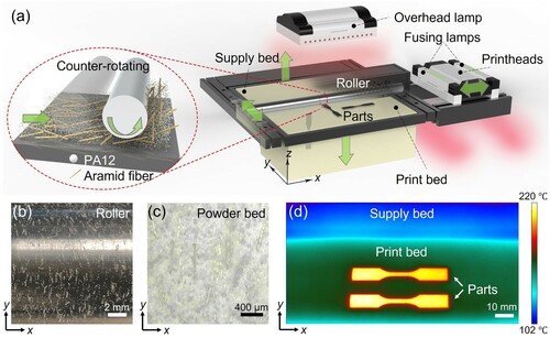
The energy input sub-process started when a carriage consisting of a printhead system and two fusing lamps passed over the print bed. Both the fusing lamps were turned on, and the printhead system in between dispensed the HP fusing agent on designated regions where the powder particles were selected to be fused. The HP fusing agent, which contains radiation-absorbing materials, can be dispensed at millions of drops per second in every single inch of the intended region through the printhead system (HP Development Company, L.P. Citation2022). The energy input was controlled by multiple independent factors including the infrared intensity (determined by power of the overhead lamp and fusing lamps), moving velocity of the carriage, scan count of the fusing lamps (i.e. the number of fusing lamps passing between two consecutive recoating steps), and hatch spacing (Chatham, Long, and Williams Citation2019).
Insufficient energy input may cause high porosity of printed parts, resulting in poor mechanical properties. The use of elevated temperature increases the macromolecular mobility, which leads to higher crystallinity of the printed parts, and thus the higher mechanical strength. However, excessive heat may cause thermal bleeding that affects the dimensional accuracy of the parts. To better address the porosity issue caused by the addition of the fibres (Jansson and Pejryd Citation2016), the scan count was set at two to increase the energy input for the fabrication of denser parts.
The printer was equipped with not only an infrared sensor for monitoring the operation of the print bed but also a thermal imaging system for recording the temperature distribution. A temperature contour of the 8 wt% AF-0.5 mm/PA12 powder bed is presented in d. The temperature distribution of the powder bed was obtained immediately after the fusing lamps were applied twice. With the aid of the radiation-absorbing material (i.e. carbon black) in the fusing agent, the PA12 powder in the designated regions reached its melting point after absorbing sufficient infrared energy. Because of their highly rigid and orientated molecular structure, the AFs exhibited high heat resistance, and their decomposition temperature was approximately 500 °C, resulting in insignificant changes in their physical features during the fusion of PA12. Hence, the AFs were uniformly embedded in the continuous PA12 matrix. When an external force is applied to the composite, part of the force can be transferred from the matrix to the fibres to resist the deformation of the matrix, leading to the enhancement of the mechanical performance.
The temperature profiles of the neat PA12 and AF-0.5 mm/PA12 parts with various fibre fractions are compared in Figure S1. In general, the composite powder became yellower with a higher fibre fraction, which could be the cause of the increase in the fusing temperature approximately from 205 °C to 220 °C. The temperature of the powder without the fusing agent was below 170 °C.
By the layer-wise manner, the fused powder and AFs were consolidated into the final part after being naturally cooled down to room temperature. The various cooling conditions led to different polymer crystallization behaviours that affected the mechanical properties of the printed parts. This is further explained in Section 3.3.4. This work defined that the lamp moving direction, the roller recoating direction, and the powder bed moving direction are along the x-, y-, and z-axes, respectively.
3.1.2. Powder properties
Powder flowability is a key property that influences the recoating process of powder. It governs the packing density of powder layers which affects the quality of the printed parts. The dynamic avalanche angle, an indicator of powder flowability, measures the cohesiveness of particles during their flow process. A small avalanche angle suggests good powder flowability, while a large avalanche angle implies undesirable powder cohesion (Zegelmeier et al. Citation2013).
The shape, size, and size distribution of powder particles are critical to the powder flowability. The addition of fibre reinforcements to powder inevitably degrades its flowability. In , with an increase in the fibre fraction from 0 wt% to 12 wt%, the medium avalanche angle increased from 48.4° to 58.4°, possibly because of the mismatch of the shape and size between the PA12 particles and AFs. Nonetheless, the flowability of the AF/PA12 composite powders is still comparable to that of some reported PBF-grade polymer powders (e.g. PA12 and thermoplastic polyurethane) with avalanche angles in the range of 40°–60° (Ziegelmeier et al. Citation2015).
Figure 2. Histograms of avalanche angle distributions and images of powders: (a) PA12 powder and (b–d) AF-0.5 mm/PA12 powders with fibre fractions of 4, 8, and 12 wt%. The avalanche angle distributions are fitted by Gaussian functions (the blue curves).
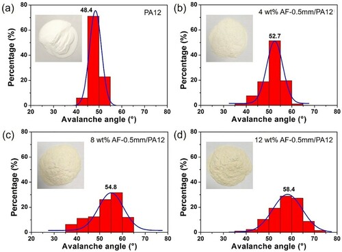
In MJF, powder with dark colours shows high radiation absorption that can enable the heat absorption of unintended regions, and thus the powder printability is limited. With the addition of AFs, the composite powder turned from white to pale yellow in various degrees (insets, ), which were still suitable for MJF because most of the energy was delivered to the designated regions of the powder bed. The surrounding powder was kept at a low temperature based on the measurement by the infrared camera, suggesting high powder recyclability. Powder recyclability, a unique feature of PBF that significantly reduces costs for commercial applications, was evaluated with the results presented in Figure S2 and Table S1.
3.2. Structure of the AF/PA12 composites
The structure of the AF/PA12 composites is determined by various factors including the material composition and the printing process. The composite powder composes the basic composite structure, in which the polymer particles form the matrix, and the fibres serve as the reinforcements. The fibre reinforcements have a preferred orientation determined by the recoating direction. To reveal the fibre arrangement in the printed parts, the fibre orientation was investigated by an optical microscope. The composite parts were polished down to the centre, and the cross-section images were obtained for the quantitative analysis of the fibre orientation via the ImageJ software (Figure S3).
The statistical characteristics of the fibre orientation distributions for AF-0.5 mm/PA12 parts with different fibre fractions (4, 8, and 12 wt%) are given in . The orientation angle ranged from 0° (i.e. along the positive direction of the x-axis) to 180°. In all cases, the preferred orientation angle of AFs was found to be approximately 90°, corresponding to the moving direction of the roller.
Table 1. Statistical characteristics of fibre orientation distributions for the AF-0.5 mm/PA12 parts with different fibre fractions (4, 8, and 12 wt%). ‘Dispersion' indicates the standard deviations of peaks of the Gaussian fitting curves, and ‘Percentage' means the percentages of the histograms within the standard deviations.
The differences among the UTS of parts measured along different directions can be explained by anisotropy of the printed composites caused by the fibre alignment. The percentage of the fibre alignment in the predominant direction increased from 54% to 63% with the increase in the fibre fraction from 4 wt% to 12 wt%. This finding also implies that a higher fibre fraction facilitates the fibre alignment along the direction of roller movement.
3.3. Mechanical properties
The mechanical properties of composites are directly related to their structures and are determined by the feeding powder, printing process, and post-process. In this section, the effects of the fibre fraction, fibre length, layer thickness, build orientation, and post-annealing process on the mechanical performance of the parts are discussed through the elucidated process–structure–property relationships. The established relationships facilitate the design of part performances and powder commercialisation for PBF.
3.3.1. Effects of the fibre fraction and fibre length
illustrates the effects of the fibre fraction and fibre length on the UTS of the AF/PA12 composites measured along the y-axis. The results of all tested groups are summarised in Table S2, and the microscopy images of the AFs with different fibre lengths are shown in Figure S4. The increase in the fibre length gave rise to poor powder flowability because of the mismatch of the shape and size between the PA12 particles and AFs, which eventually caused a recoating problem. The maximum fibre fractions of composites with the fibre lengths of 0.5, 0.7, and 1.2 mm were 14, 10, and 4 wt%, respectively, beyond which the powder recoating will fail.
Figure 3. Effect of the fibre fraction on the UTS of the AF/PA12 composites measured along the y-direction for different fibre lengths (0.5, 0.7, and 1.2 mm). The maximum fibre fractions of composites with fibre lengths of 0.5, 0.7, and 1.2 mm were 14, 10, and 4 wt%, respectively.
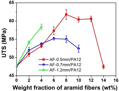
When the fiber weight fraction is not larger than 4 wt%, the UTS of the printed composite increases as the fiber length increases. At a large fiber weight fraction, an increase in the fiber length will significantly reduce the flowability of the composite powder and increase the porosity of the printed composites, thereby degrading their mechanical properties. In general, higher fibre fractions and larger fibre lengths result in better reinforcement of composites. However, for PBF printing, high fibre fractions and long fibre lengths have limited or even adverse effect on the composite reinforcement because of the poor powder flowability. In our work, the optimum fibre fractions with fibre lengths of 0.5, 0.7, and 1.2 mm for the composite parts were determined as 8, 6, and 4 wt%, respectively, indicating that a smaller fibre length enabled higher fibre loading (a higher weight fraction) to achieve better mechanical performance.
The porosity of the neat PA12 and AF/PA12 composites shown in Figure S5 was quantitatively measured by micro-CT. The porosity values of the samples with 0, 4, 8, and 12 wt% AFs were 0.84%, 2.70%, 5.26%, and 7.20%, respectively. The porosity of the neat PA12 was lower than that obtained in the previous studies (Cai et al. Citation2021; O’ Connor, Dickson, and Dowling Citation2018; Jansson and Pejryd Citation2016). The low porosity could be attributed to the small amount of residual carbon black and 2-pyrrolidone in the HP fusing agent as well as the high energy input used. The addition of AFs in PA12 powder decreased the powder flowability, leading to an increased number of voids in the powder bed. Consequently, the printed composite parts had larger porosity than the neat PA12 part, which was in direct proportion to the fibre fraction.
3.3.2. Effect of the layer thickness
The thickness of the building layer is a critical parameter influencing the printing resolution, printing efficiency, and quality of the products. The effect of the layer thickness on the tensile properties was investigated for the composite with optimal performance (8 wt% AF-0.5 mm/PA12). shows the tensile properties and fractographs of the parts fabricated at layer thicknesses of 60, 80, 100, 120, and 140 μm while other printing parameters were kept constant. Based on the tensile test results (detailed in Table S3), the optimal layer thickness was determined as 80 μm.
Figure 4. Effect of the layer thickness on the tensile properties of the 8 wt% AF-0.5 mm/PA12 parts: (a) variations in the UTS and Young’s modulus with different layer thicknesses (60, 80, 100, 120, and 140 μm) and (b–f) fractographs of the printed parts.
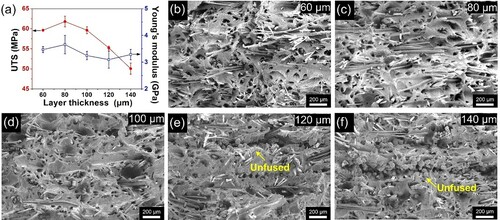
The printed parts with the layer thickness of 60 μm showed lower dimensional accuracy due to thermal bleeding raised by excessive energy input. Increasing the powder layer thickness can increase the packing density of composite powder (Tan et al. Citation2021) but inevitably reduces the resolution of printed products. The layer thickness of 100 μm was chosen as the upper limit since lack of fusion was observed (e,f) when the layer was thicker than 100 μm. The lack of fusion may be attributed to the insufficient energy intensity, time, and amount of fusing agent used, which lead to the partial penetration of the powder layer. Hence, a thicker layer requires high energy intensity, an extended exposure time, or a greater amount of fusing agent for the full penetration of the powder layer during the printing.
3.3.3. Effect of the build orientation
Based on the optimised fibre fraction, fibre length, and layer thickness, the effect of the build orientation on the mechanical properties was further investigated using the parts with a fibre length of 0.5 mm and layer thickness of 80 μm. a,b illustrate the UTS and Young’s moduli of the neat PA12 and AF-0.5 mm/PA12 parts with various fibre fractions measured along the x-, y-, and z-directions. The obtained values are listed in Tables S2 and S4. The UTS and Young's moduli of the composite parts measured along the y-direction showed the best performance. Specifically, the composite with 8 wt% AFs exhibited the highest UTS that was 61.79 MPa (increased by 27%), and the composite with 12 wt% AFs showed the highest modulus of 4.71 GPa (increased by 179%), as compared with the unreinforced counterpart.
Figure 5. Effect of the build orientation on the tensile properties of neat PA12 and 8 wt% AF-0.5 mm/PA12 parts: (a) the UTS and (b) Young’s moduli of the parts measured along the x-, y-, and z-directions, (c) stress–strain curves of the neat PA12 and 8 wt% AF-0.5 mm/PA12 parts measured along the x-, y-, and z-directions, and (d–f) fractographs of the 8 wt% AF-0.5 mm/PA12 parts fractured under tensile loading along the x-, y-, and z-directions.
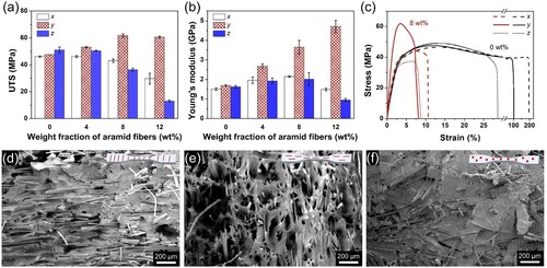
In contrast, the UTS and Young's moduli of the composite parts measured in the x- and z-directions showed lower performance, particularly in the z-direction, since most of the fibres were confined in the x–y plane. c shows the stress–strain curves of the 8 wt% AF/PA12 and neat PA12 parts measured in the three directions. Similarly to the situations seen in most of the fibre-reinforced composites, the increase in strength and modulus is normally achieved at the cost of increased brittleness, which results in the decreased elongation at break (Figure S6). This may be caused by the diminished continuity of the polymer matrix with the fibre-induced porosity. Therefore, the enhancement in the strength and modulus of the AF/PA12 composites is compromised by the reduction in the ductility. When the ductility is the priority in some applications, a polymer composite with a fibre fraction of 2 wt% or 4 wt% will be preferable. The elongation at break of the neat PA12 part is much higher than those in other studies (Cai et al. Citation2021; O’ Connor, Dickson, and Dowling Citation2018; Sillani et al. Citation2019), which may be caused by the relatively fast cooling process of our MJF testbed and the high energy input.
The fractographs of the 8 wt% AF-0.5 mm/PA12 samples are shown in d–f. The fibre alignment in the recoating direction can be notably observed. The fibres were predominantly oriented in the x–y plane and thus did not contribute to the interlayer strength. The smooth fracture surfaces of the parts fractured along the x- and z-directions demonstrate that the fracture mode was brittle failure. For the composite fractured along the y-direction, the fibres were oriented perpendicular to the fracture surface, and some holes were created in the matrix as the fibres were dislodged. The aligned fibres enhanced the mechanical strength through preventing crack propagation by means of energy absorption processes such as the fracture, debonding, and pull-out of the fibres in the PA12 matrix. In addition, the flexural properties of the neat PA12 and AF-0.5 mm/PA12 composites are shown in Figure S7 and Table S5. Overall, the anisotropic behaviour suggests that the main load-bearing direction of the printed parts is recommended to be set in the y-direction.
3.3.4. Effect of the post-annealing process
For the MJF testbed used in this work, the small size of the build platform and the relatively open working area made the natural cooling process faster than that in a commercial MJF printer. A fast cooling process causes varied local thermal contraction in a printed part, which may result in the formation of residual stress and the final part warpage. Moreover, the fast cooling process leads to low crystallinity that decreases the mechanical strength and modulus of the part. Hence, a post-annealing process was conducted to relieve the residual stress and increase the crystallinity of the AF/PA12 composite parts. The annealing temperature of the semicrystalline polymer is often implemented in the temperature window above the glass transition temperature Tg and below the melting point Tm. By assuming the absence of deformation, a high annealing temperature can allow adequate segmental motion for crystallization. Based on our previous work on optimising the annealing temperature setting (Liu et al. Citation2021), the process was conducted at the optimised temperature of 170 °C for 4 h.
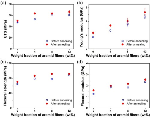
illustrates the mechanical performances of the neat PA12 part and AF-0.5 mm/PA12 composites before and after annealing treatment. The obtained values are also presented in detail in Table S6. Both the tensile and flexural performances of the parts were improved by the annealing process. Specifically, the 12 wt% AF-0.5 mm/PA12 composite exhibited the highest UTS, Young’s modulus, and flexural modulus of 66.44 MPa, 5.34 GPa, and 2.54 GPa, respectively, and the 8 wt% AF-0.5 mm/PA12 composite showed the highest flexural strength of 91.82 MPa. Interestingly, the 4 wt% AF-0.5 mm/PA12 composite revealed a more significant improvement in strength than the other composites. To fully understand the impact of annealing on the crystallization behaviour, DSC and XRD were performed, and the results are shown in Table S7 and Figures S8 and S9.
Figure 6. Effect of the post-annealing process on the tensile and flexural properties of neat PA12 and AF-0.5 mm/PA12 parts with fibre fractions of 4, 8, and 12 wt% measured along the y-direction.
3.3.5. Comparison of mechanical properties
With the addition of the high-performance AF reinforcements and property optimisation, the MJF-printed AF/PA12 composites exhibited outstanding mechanical properties among the composites printed by PBF. To date, commercial reinforcements including GBs, GFs, and CFs have been used in PBF, typically in SLS or MJF. The mechanical properties of the AF/PA12 composites measured along the recoating direction and previously reported PBF-printed composites are compared in . Generally, the 12 wt% AF-0.5 mm/PA12 composite fabricated in this work outperforms most of the reported composites in terms of the UTS and Young’s modulus. The mechanical performance of the composite is further enhanced after annealing. Although the mechanical properties of CF/PA12 composites are superior to those of the composites fabricated in this work, CFs are unsuitable for MJF due to their dark colour. Therefore, the AF/PA12 composite powder developed in this work can be considered as a promising candidate for MJF.
Table 2. Comparison of the mechanical properties of the SLS- and MJF-printed neat PA12 part and GB/PA12, GF/PA12, CF/PA12, and AF/PA12 composites measured along the recoating direction.
Known for their unique structure, AFs enable the composites to have high mechanical performance and light weight. Among the most commonly used fibres in PBF-printed composites, the density of AFs (1.44 g/cm3) is generally lower than those of GFs (∼2.5 g/cm3) and CFs (∼1.8 g/cm3). In contrast to GFs, GBs, or CFs which generally increases the densities of the composite parts, AFs resulted in no significant changes in part density when they were added (). The densities of the AF-reinforced composite parts were in the range of 0.97–1.03 g/cm3 (depending on the fibre fraction), which were comparable to the density of the neat PA12 part (1.02 g/cm3).
Table 3. Comparison of the specific strength of various materials.
As shown in , the specific strength (i.e. the strength-to-weight ratio) of the annealed 12 wt% AF-0.5 mm/PA12 composite (64.50 kN·m/kg) measured along the recoating direction was comparable to that of stainless steel 304 (64.38 kN·m/kg). The specific strength values of composite parts printed by MJF (e.g. GB/PA12 and GF/PA12) and other composite parts that can be only printed by SLS (e.g. GB/CF/PA12 and CF/PA12) are also listed in . The AF/PA12 composites reported in this work are lighter and stronger than the glass-filled PA12 composites, revealing the great commercial value of the former.
4. Conclusions
A new type of composite powder, AF/PA12, was developed and applied to fabricating 3D printed parts with enhanced performance using an MJF testbed. The process–structure–property relationships were built by comprehensively analysing the manufacturing process of the AF/PA12 composites and the influence of the experiment parameters on the mechanical properties. The MJF printing process of the composites, including the powder recoating, energy input, and cooling sub-processes, was presented in detail. The fibre alignment caused by the recoating process was investigated by an optical microscope to reveal the structure of the composites, which comprised the polymer as the matrix and fibres as the reinforcements. The effects of the material composition (i.e. the fibre fraction and fibre length), printing parameters (i.e. the layer thickness and build orientation), and post-annealing process on the mechanical properties of the printed parts were systematically investigated and explained through the process–structure–property relationship to optimise the mechanical properties of the composites.
The results showed that the composite parts printed using a fibre fraction of 12 wt%, a fibre length of 0.5 mm, and a layer thickness of 80 μm exhibited optimal mechanical performance by achieving high UTS, Young’s modulus, flexural strength, and flexural modulus values of 60.61 MPa, 4.71 GPa, 88.45 MPa, and 2.34 GPa, respectively. After the post-annealing process, the mechanical properties of the AF/PA12 parts were further enhanced. In particular, the UTS, Young’s modulus, flexural strength, and flexural modulus were increased up to 66.44 MPa, 5.34 GPa, 91.62 MPa, and 2.54 GPa, respectively, while the densities were maintained at the same level as that of the neat PA12 part. The specific strength of the AF/PA12 composites (up to 64.50 kN·m/kg) was comparable to that of stainless steel 304.
The high-strength light-weight AF/PA12 composite possesses the best mechanical performance among the reported MJF-printed parts and is competitive with most nylon composites printed by SLS. This work demonstrates the manufacturing methodology of the AF/PA12 composites and their potential for a broad range of applications.
Supplemental Material
Download MS Word (1.3 MB)Acknowledgements
This study is supported under the RIE2020 Industry Alignment Fund – Industry Collaboration Projects (IAF-ICP) Funding Initiative, as well as cash and in-kind contribution from the industry partner, HP Inc. The authors thank Mr. Boyuan Li for the XRD characterisation and Ms. Meixin Zhou for the DSC characterisation.
Disclosure statement
No potential conflict of interest was reported by the author(s).
Additional information
Funding
Notes on contributors
Jiayao Chen
Jiayao Chen is a research fellow in HP-NTU Digital Manufacturing Corporate Lab, School of Mechanical and Aerospace Engineering, Nanyang Technological University, Singapore.
Pengfei Tan
Pengfei Tan is a research fellow in HP-NTU Digital Manufacturing Corporate Lab, School of Mechanical and Aerospace Engineering, Nanyang Technological University, Singapore.
Xiaojiang Liu
Xiaojiang Liu is a research fellow in HP-NTU Digital Manufacturing Corporate Lab, School of Mechanical and Aerospace Engineering, Nanyang Technological University, Singapore.
Wei Shian Tey
Wei Shian Tey is a PhD candidate in HP-NTU Digital Manufacturing Corporate Lab, School of Mechanical and Aerospace Engineering, Nanyang Technological University, Singapore.
Adrian Ong
Adrian Ong is a senior engineer in HP-NTU Digital Manufacturing Corporate Lab, School of Mechanical and Aerospace Engineering, Nanyang Technological University, Singapore, and HP R&D Singapore Pte. Ltd., Singapore.
Lihua Zhao
Lihua Zhao is the Global Head of 3D Lab at HP Labs, HP Inc., USA, and a principal investigator in HP-NTU Digital Manufacturing Corporate Lab, School of Mechanical and Aerospace Engineering, Nanyang Technological University, Singapore.
Kun Zhou
Kun Zhou is an Associate Professor in HP-NTU Digital Manufacturing Corporate Lab, School of Mechanical and Aerospace Engineering, Nanyang Technological University, Singapore.
References
- Afshari, M., D. J. Sikkema, K. Lee, and M. Bogle. 2008. “High Performance Fibers Based on Rigid and Flexible Polymers.” Polymer Reviews 48 (2): 230–274.
- AZoM. 2021. “Stainless steel - Grade 304 (UNS S30400).” https://www.azom.com/article.aspx?ArticleID = 965.
- Cai, C., W. S. Tey, J. Chen, W. Zhu, X. Liu, T. Liu, L. Zhao, and K. Zhou. 2021. “Comparative Study on 3D Printing of Polyamide 12 by Selective Laser Sintering and Multi Jet Fusion.” Journal of Materials Processing Technology 288: 116882.
- Chatham, C. A., T. E. Long, and C. B. Williams. 2019. “A Review of the Process Physics and Material Screening Methods for Polymer Powder bed Fusion Additive Manufacturing.” Progress in Polymer Science 93: 68–95.
- Chen, B., R. Davies, Y. Liu, N. Yi, D. Qiang, Y. Zhu, and O. Ghita. 2020. “Laser Sintering of Graphene Nanoplatelets Encapsulated Polyamide Powders.” Additive Manufacturing 35: 101363.
- Chen, J., X. Liu, Y. Tian, W. Zhu, C. Yan, Y. Shi, L. B. Kong, H. J. Qi, and K. Zhou. 2022. “3D-printed Anisotropic Polymer Materials for Functional Applications.” Advanced Materials, 34, 2102877.
- Craft, G., J. Nussbaum, N. Crane, and J. P. Harmon. 2018. “Impact of Extended Sintering Times on Mechanical Properties in PA-12 Parts Produced by Powderbed Fusion Processes.” Additive Manufacturing 22: 800–806.
- Dickson, A. N., J. N. Barry, K. A. McDonnell, and D. P. Dowling. 2017. “Fabrication of Continuous Carbon, Glass and Kevlar Fibre Reinforced Polymer Composites Using Additive Manufacturing.” Additive Manufacturing 16: 146–152.
- Dong, H., and L. Chang. 2021. “The Effects of Printing Directions on the Compression Behavior of the Re-Entrant Structure Produced by 3D Printing Technology.” Journal of Micromechanics and Molecular Physics 6 (2): 2141004.
- EOS. 2021. “EOS polymers for additive manufacturing polyamide 12.” https://www.eos.info/en/additive-manufacturing/3d-printing-plastic/sls-polymer-materials/polyamide-pa-12-alumide.
- Fischer, S., A. Pfister, V. Galitz, B. Lyons, C. Robinson, K. Rupel, R. Booth, and S. Kubiak. 2015. “A high performance material for aerospace applications: Development of carbon fiber filled PEKK for laser sintering. “ Paper presented at the Proceedings of the 26th Annual International Solid Freeform Fabric Symposium, Austin, TX, USA.
- HP Development Company, L.P. 2017. “HP 3D high reusability PA12 glass beads.” https://cimquest-inc.com/resource-center/HP/Materials/HP-PA12GB-Datasheet.pdf.
- HP Development Company, L.P. 2020. “HP 3D Printing materials for the HP Jet Fusion 5200 Series 3D Printing Solution.” https://h20195.www2.hp.com/V2/getpdf.aspx/4AA7-7084ENW.pdf.
- HP Development Company, L.P. 2022. “HP MJF handbook.” https://reinvent.hp.com/us-en-3dprint-mjfhandbook.
- Jansson, A., and L. Pejryd. 2016. “Characterisation of Carbon Fibre-Reinforced Polyamide Manufactured by Selective Laser Sintering.” Additive Manufacturing 9: 7–13.
- Jing, W., H. Chen, Q. Wu, H. Liu, and Z. Luo. 2017. “Surface Modification of Carbon Fibers and the Selective Laser Sintering of Modified Carbon Fiber/Nylon 12 Composite Powder.” Materials & Design 116: 253–260.
- Kim, Y., Y. Kim, F. Libonati, and S. Ryu. 2019. “Designing Tough Isotropic Structural Composite Using Computation, 3D Printing and Testing.” Composites Part B: Engineering 167: 736–745.
- Lanzl, L., K. Wudy, and D. Drummer. 2020. “The Effect of Short Glass Fibers on the Process Behavior of Polyamide 12 During Selective Laser Beam Melting.” Polymer Testing 83: 106313.
- Liu, X., W. S. Tey, J. Y. C. Choo, J. Chen, P. Tan, C. Cai, A. Ong, L. Zhao, and K. Zhou. 2021. “Enhancing the Mechanical Strength of Multi Jet Fusion–Printed Polyamide 12 and its Glass Fiber-Reinforced Composite via High-Temperature Annealing.” Additive Manufacturing 46: 102205.
- Mazzoli, A., G. Moriconi, and M. G. Pauri. 2007. “Characterization of an Aluminum-Filled Polyamide Powder for Applications in Selective Laser Sintering.” Materials & Design 28 (3): 993–1000.
- Melenka, G. W., B. K. O. Cheung, J. S. Schofield, M. R. Dawson, and J. P. Carey. 2016. “Evaluation and Prediction of the Tensile Properties of Continuous Fiber-Reinforced 3D Printed Structures.” Composite Structures 153: 866–875.
- Mousa, A. A. 2014. “The Effects of Content and Surface Modification of Filler on the Mechanical Properties of Selective Laser Sintered polyamide12 Composites.” Jordan Journal of Mechanical and Industrial Engineering 8 (5): 265–274.
- O’ Connor, H. J., A. N. Dickson, and D. P. Dowling. 2018. “Evaluation of the Mechanical Performance of Polymer Parts Fabricated Using a Production Scale Multi Jet Fusion Printing Process.” Additive Manufacturing 22: 381–387.
- O' Connor, H. J., and D. P. Dowling. 2020. “Comparison Between the Properties of Polyamide 12 and Glass Bead Filled Polyamide 12 Using the Multi Jet Fusion Printing Process.” Additive Manufacturing 31: 100961.
- Pei, S., K. Wang, C.-B. Chen, J. Li, Y. Li, D. Zeng, X. Su, and H. Yang. 2021. “Process-structure-property Analysis of Short Carbon Fiber Reinforced Polymer Composite via Fused Filament Fabrication.” Journal of Manufacturing Processes 64: 544–556.
- Prakhash, N., P. Sakthivel, M. D. Karthick, P. Swaminathan, and D. Z. Rahman. 2021. “Mechanical Properties of RCC Column with Kevlar and Banana Fibre Wrapping.” Materials Today: Proceedings 37: 2986–2990.
- Ravoori, D., L. Alba, H. Prajapati, and A. Jain. 2018. “Investigation of Process-Structure-Property Relationships in Polymer Extrusion Based Additive Manufacturing Through in Situ High Speed Imaging and Thermal Conductivity Measurements.” Additive Manufacturing 23: 132–139.
- Salazar, A., A. Rico, J. Rodríguez, J. S. Escudero, R. Seltzer, and F. M. de la Escalera Cutillas. 2014. “Fatigue Crack Growth of SLS Polyamide 12: Effect of Reinforcement and Temperature.” Composites Part B: Engineering 59: 285–292.
- Sculpteo. 2021. “Nylon 3200 glass-filled 3D printing material.” https://www.sculpteo.com/en/materials/sls-material/glass-filled-nylon-material/.
- Sillani, F., R. G. Kleijnen, M. Vetterli, M. Schmid, and K. Wegener. 2019. “Selective Laser Sintering and Multi Jet Fusion: Process-Induced Modification of the raw Materials and Analyses of Parts Performance.” Additive Manufacturing 27: 32–41.
- Tan, P., F. Shen, W. S. Tey, and K. Zhou. 2021. “A Numerical Study on the Packing Quality of Fibre/Polymer Composite Powder for Powder bed Fusion Additive Manufacturing.” Virtual and Physical Prototyping 16 (sup1): S1–S18.
- Tan, L. J., W. Zhu, and K. Zhou. 2020. “Recent Progress on Polymer Materials for Additive Manufacturing.” Advanced Functional Materials 30 (43): 2003062.
- Tofail, S. A. M., E. P. Koumoulos, A. Bandyopadhyay, S. Bose, L. O’Donoghue, and C. Charitidis. 2018. “Additive Manufacturing: Scientific and Technological Challenges, Market Uptake and Opportunities.” Materials Today 21 (1): 22–37.
- Wang, Y., D. Rouholamin, R. Davies, and O. R. Ghita. 2015. “Powder Characteristics, Microstructure and Properties of Graphite Platelet Reinforced Polyether-Ether-Ketone Composites in High Temperature Laser Sintering (HT-LS).” Materials & Design 88: 1310–1320.
- Williams, J. M., A. Adewunmi, R. M. Schek, C. L. Flanagan, P. H. Krebsbach, S. E. Feinberg, S. J. Hollister, and S. Das. 2005. “Bone Tissue Engineering Using Polycaprolactone Scaffolds Fabricated via Selective Laser Sintering.” Biomaterials 26 (23): 4817–4827.
- WINDFORM. 2021. “WINDFORM SP.” http://www.windform.com/windform-sp.html.
- Xu, Z., Y. Wang, D. Wu, K. P. Ananth, and J. Bai. 2019. “The Process and Performance Comparison of Polyamide 12 Manufactured by Multi Jet Fusion and Selective Laser Sintering.” Journal of Manufacturing Processes 47: 419–426.
- Yan, C., G. Ma, A. Chen, Y. Chen, J. Wu, W. Wang, S. Yang, and Y. Shi. 2020. “Additive Manufacturing of Hydroxyapatite and its Composite Materials: A Review.” Journal of Micromechanics and Molecular Physics 5 (3): 2030002.
- Yan, C., Y. Shi, J. Yang, and J. Liu. 2012. “Multiphase Polymeric Materials for Rapid Prototyping and Tooling Technologies and Their Applications.” Composite Interfaces 17 (2–3): 257–271.
- Yang, J., Y. Shi, and C. Yan. 2010. “Selective Laser Sintering of Polyamide 12/Potassium Titanium Whisker Composites.” Journal of Applied Polymer Science 117 (4): 2196–2204.
- Yuan, S., J. Li, X. Yao, J. Zhu, X. Gu, T. Gao, Y. Xu, and W. Zhang. 2020. “Intelligent Optimization System for Powder bed Fusion of Processable Thermoplastics.” Additive Manufacturing 34: 101182.
- Yuan, S., S. Li, J. Zhu, and Y. Tang. 2021. “Additive Manufacturing of Polymeric Composites from Material Processing to Structural Design.” Composites Part B: Engineering 219:108903.
- Yuan, S., F. Shen, C. K. Chua, and K. Zhou. 2019. “Polymeric Composites for Powder-Based Additive Manufacturing: Materials and Applications.” Progress in Polymer Science 91: 141–168.
- Yuan, S., Y. Zheng, C. K. Chua, Q. Yan, and K. Zhou. 2018. “Electrical and Thermal Conductivities of MWCNT/Polymer Composites Fabricated by Selective Laser Sintering.” Composites Part A: Applied Science and Manufacturing 105: 203–213.
- Zanjanijam, A. R., I. Major, J. G. Lyons, U. Lafont, and D. M. Devine. 2020. “Fused Filament Fabrication of PEEK: A Review of Process-Structure-Property Relationships.” Polymers 12 (8): 1665.
- Zegelmeier, S., F. Wöllecke, C. Tuck, R. Goodridge, and R. Hague. 2013. “Characterizing the Bulk & Flow Behaviour of LS Polymer Powders.” International Solid Freeform Fabrication Symposium, 354–367.
- Zhao, J., Q. Li, F. Jin, and N. He. 2021. “Digital Light Processing 3D Printing Kevlar Composites Based on Dual Curing Resin.” Additive Manufacturing 41: 101962.
- Ziegelmeier, S., P. Christou, F. Wöllecke, C. Tuck, R. Goodridge, R. Hague, E. Krampe, and E. Wintermantel. 2015. “An Experimental Study Into the Effects of Bulk and Flow Behaviour of Laser Sintering Polymer Powders on Resulting Part Properties.” Journal of Materials Processing Technology 215: 239–250.