
 ?Mathematical formulae have been encoded as MathML and are displayed in this HTML version using MathJax in order to improve their display. Uncheck the box to turn MathJax off. This feature requires Javascript. Click on a formula to zoom.
ABSTRACT
The Eggshell fabrication process combines the 3D printing of formwork with the simultaneous casting of a fast-hardening concrete. One limiting factor to reaching mass-market adoption is a suitable reinforcing strategy. In this study, a reinforcement strategy combining steel reinforcing bars with steel fibres is explored. A series of eight beams were produced using the Eggshell process or conventionally cast. The longitudinal reinforcement was provided by two reinforcing bars, and two types of fibres, either mixed with the concrete or placed and aligned between the cast concrete layers, were used as shear reinforcement. The results showed that combining conventional longitudinal reinforcement and fibres as shear reinforcement is a suitable strategy. These findings were applied to fabricate an optimised beam with a volume reduction of almost 50%. The structural performance of this beam was similar to the beam with a rectangular cross-section with the same reinforcement strategy showing the potential of Eggshell in combination with an innovative reinforcement strategy to produce material-efficient structural concrete elements.
GRAPHICAL ABSTRACT
1. Introduction
The building and construction industry is one of the largest contributors to global CO2 emissions. The construction industry is responsible for 10% of total emissions (United Nations Environment Programme Citation2020), with the manufacturing of cement alone resulting in 8% of worldwide CO2 emissions (Monteiro, Miller, and Horvath Citation2017). Therefore, to move towards a sustainable future for construction, the way buildings are constructed must be reconsidered (McKinsey & Company Citation2016). Since concrete and cement have a high impact on the environment, these materials must be used sustainably. Research shows that it is possible to reduce CO2 emissions from concrete construction by up to 70% by 2050 (Favier et al. Citation2018). Achieving such a reduction requires efforts from cement and concrete producers to decrease the carbon footprint of cement and concrete, but also from structural engineers and designers, to design structurally efficient concrete structures with minimum material use (Favier et al. Citation2018; Habert et al. Citation2020).
However, traditional construction methods are not well suited for producing the non-standard, curved geometries that often characterise structurally efficient designs. Digital Fabrication with Concrete (DFC) has recently emerged as a field aiming to overcome these limitations (Wangler et al. Citation2019). One aspect of DFC is the introduction of novel fabrication methods, such as the fabrication of concrete formwork using 3D printing. These formworks allow for higher geometric flexibility than typical construction formworks. Various 3D printing technologies can be used to produce formwork. One particularly suitable method is using Fused Deposition Modeling (FDM) 3D printing. FDM 3D printing has a relatively low cost compared to other methods such as binder jetting, and the equipment for it is widely available (Wu, Wang, and Wang Citation2016).
Several recent projects have investigated the use of FDM 3D printing for formwork production (Peters Citation2014; Jipa, Bernhard, and Dillenburger Citation2017; Naboni and Breseghello Citation2018; Leschok and Dillenburger Citation2019). Three main challenges can be identified in the application of 3D printed formwork:
| (1) | Reinforcing the concrete elements. | ||||
| (2) | Addressing hydrostatic pressure on the thermoplastic formwork. | ||||
| (3) | Increasing the scale and speed of the 3D printing process. | ||||
The research project Eggshell (Burger et al. Citation2020) is a novel fabrication process for non-standard concrete structures using FDM 3D printing. Eggshell addresses the previously mentioned challenges by (1) combining 3D printed formwork with passive reinforcement (Burger et al. Citation2020), (2) using a fast-hardening, set-on-demand concrete that minimises the formwork pressure (Lloret-Fritschi et al. Citation2020; Reiter et al. Citation2020), and (3) making use of an industrial robotic arm with a thermoplastic extruder. The Eggshell fabrication process consists of 3D printing a thin formwork whilst simultaneously casting a self-compacting concrete into the formwork. A detailed explanation of the fabrication process can be found in Section 3.3. So far, it has been shown that Eggshell can be used to produce load-bearing concrete columns. However, even though Eggshell offers the potential for designing other elements with higher potentials for structural optimisation, this has not yet been demonstrated and validated.
The inclusion of reinforcement is one of the primary challenges for Eggshell to exploit its geometric possibilities fully. In recent years, various reinforcement strategies have been proposed for DFC. The focus of these strategies lies mainly in 3D Concrete Printing (3DCP). Details on these strategies can be found in various reviews (Asprone et al. Citation2018; Menna et al. Citation2020; Kloft et al. Citation2020; Mechtcherine et al. Citation2021).
For Eggshell, the feasibility of using conventional reinforcing cages has already been demonstrated for the fabrication of a non-standard column (Burger et al. Citation2020). However, the use of conventional cages limits the geometric flexibility that can be achieved.
Therefore, in this study, a different, more flexible reinforcement strategy for Eggshell is explored, combining its geometrical flexibility with reliable structural performance for a lasting impact on the construction industry and a mass-market adaptation. The focus of this study lies on the load-bearing behaviour assessed through structural testing. A set of beams with rectangular cross-section and different reinforcement strategies produced with the Eggshell technology is tested until failure. The combined use of conventional reinforcement (ensuring a ductile response) and fibre reinforcement (providing a high degree of geometric flexibility) is explored for the reinforcement strategy. The potential for structural optimisation and geometrical flexibility is shown by producing a materially optimised beam. The structural performance of all beams is assessed and simplified models are presented to investigate the effectiveness of the different strategies.
2. Investigated reinforcement strategies
The reinforcement strategy for this study combines conventional continuous longitudinal reinforcement with shear reinforcement. The longitudinal reinforcement carries the main tensile loads under bending. Therefore, this reinforcement must show a well predictable and ductile response (i.e. conventional reinforcement). The structural requirements for the shear reinforcement are lower than for the longitudinal one. A hardening response of the structural member can be reached even if the shear reinforcement shows a softening response provided that sufficient longitudinal reinforcement is provided (Kaufmann, Mata-Falcón, and Amin Citation2019). Therefore, more innovative and geometrically flexible reinforcement approaches such as fibre reinforcement can be used as shear reinforcement. In a recent study by Gebhard et al. (Citation2021) such reinforcement strategies were tested for a set of 3D printed beams and showed promising results.
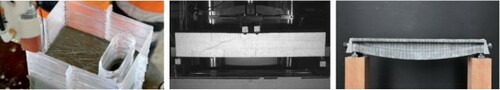
In this experimental study, the longitudinal reinforcement consists of conventional deformed steel bars. During production, a void is printed inside the beams to allow for the post-installation of this reinforcement (Figure ). Once the reinforcement is installed, the void is grouted to ensure proper bond. Steel fibres are used as shear reinforcement, added during the simultaneous production of the ultra-thin formwork and the concrete casting. Fibres do not hinder geometric flexibility, and their content can be adjusted according to the structural requirements. For DFC, the addition of fibres poses various challenges as the concrete is typically pumped. This pumpability requirement results in the limitation of suitable fibres to small and expensive fibres. Therefore, in addition to adding fibres to the mix, this study also investigates the suitability of the aligned interlayer fibre reinforcement approach in the Eggshell process (Gebhard et al. Citation2020, Citation2021). In this approach the fibres are added separately between the layers of cast concrete. This process allows the use of long inexpensive standard end-hooked fibres, and their orientation can be controlled to increase the efficiency of the fibres. Therefore, by adding the fibres separately and controlled, there is no interference with the concreting process, and the mechanical performance is expected to be higher than if the fibres were randomly dispersed. The use of longitudinal reinforcement without any shear reinforcement and conventional casting of concrete are studied as a reference. A video of this experimental campaign was presented at the fib Conceptual Design of Structures 2021 symposium (Gebhard et al. Citation2021) and can be viewed here: https://youtu.be/Kwtpozc82WUfib.
Figure 1. Geometry and test set up of the rectangular beams produced with Eggshell (dimensions in [mm]).
![Figure 1. Geometry and test set up of the rectangular beams produced with Eggshell (dimensions in [mm]).](/cms/asset/592965c4-7ce6-40c0-be53-83390acae480/nvpp_a_2041873_f0001_ob.jpg)
3. Materials and methods
3.1. Overview of the testing campaign
The experimental campaign consisted of nine beams: eight beams with a rectangular cross-section and one with optimised geometry. The optimised beam will be described further in Section 5. The eight rectangular beams investigated the influence of parameters including the production method (i.e. conventional casting versus Eggshell, using a batch-by-batch casting process), the use of short fibres mixed into the concrete and long end-hooked fibres placed between the casting steps. An overview of the beams and the investigated parameters is given in Table . Each beam listed in the table represents a single test. Therefore, except for the cast beams without shear reinforcement (R-C#1 and R-C#2), there was no replication. The geometry and the longitudinal reinforcement were kept constant, as shown in Figure . The inner void was present only in the Eggshell beams for the post-installation of the longitudinal reinforcement. The rectangular beams had a cross-section with a width mm, a height h=150 mm, and a length of 900 mm. The main span was 860 mm, and the shear span a was 395 mm. The longitudinal reinforcement consisted of two
14 mm steel reinforcing bars with a static depth d=120 mm. Hence, the shear span to static depth ratio a/d was 3.3. For the cast samples, the reinforcing bars were placed inside a formwork, and the concrete was cast conventionally. For casting, the same concrete as for the Eggshell process was used. Since the concrete was self-compacting, no vibration was needed. However, the high fluidity of the concrete led to some instabilities for the large casting volumes. The Eggshell beams were produced vertically, i.e. standing on the small face (see Section 3.3), as opposed to the conventional fabrication of concrete beams, which are typically fabricated lying down on the largest face. The outer formwork and the inner void were printed continuously, concrete was cast at approximately every 20 mm. For the beam with interlayer fibre reinforcement (R-E-IF-03), the fibres were placed manually between the layers of concrete. After production, the reinforcing bars were placed inside the void and grouted. The longitudinal reinforcement was anchored by steel plates (see Figure ). The finished beams were then tested in four-point bending and their side face provided with a speckle pattern to enable surface strain measurements with Digital Image Correlation (DIC). In the following sections, the various materials and production steps are explained in more detail.
Table 1. Overview of tested beams (Abbreviations: R = rectangular, O = optimised; C = cast, E = Eggshell; S = straight, RV = rough; SF = short fibres, IF = interlayer fibres; volumetric fibre content).
3.2. Materials
3.2.1. Concrete
The fabrication process used in this study relies on set-on-demand casting, a method of controlling the hydration of concrete (Lloret et al. Citation2015; Reiter et al. Citation2020). The principle of set-on-demand is that a retarded (delayed hydration) concrete is initially mixed, and then accelerating admixtures are added to a small batch of the retarded concrete to ensure the cast material sets within the required time. By using set-on-demand casting, the pressure on the formwork is reduced, enabling the use of a thin formwork without causing breakage. A previously developed concrete mix with a maximum aggregate size of 4 mm was used for this study. Although theoretically larger aggregates could be used, this aggregate size was chosen because of the small dimensions of the cross-section. The concrete was retarded to ensure a long enough working time (6–8 hours). During the Eggshell production, small batches of the mix were accelerated and cast. The material composition was taken from the supplementary material of Burger et al. (Citation2020) (‘Twisting Column’ mix). The cement content of the material mix was 592 kg/, with a w/c ratio of 0.4. The accelerator concentration was 24.5 g/L. In some cases, the superplasticizer content was slightly varied to adjust for the moisture content of the sand. During the production of R-C#2 (which was horizontally cast inside a formwork, see Section 3.3), air entrapment issues were locally observed at the top (compression zone). However, they could be avoided for all other specimens by letting the concrete rest for a few minutes after adding the accelerator (see details of the production in Section 3.3). After casting, all samples were left in the laboratory until testing to simulate curing conditions similar to a construction site. The formwork was removed one week before testing.
The concrete properties were measured on the day of testing. The compression and E-modulus tests were performed on standard cylinders of 150 mm diameter and 300 mm height. The tensile strength was measured via double punch tests (Chen Citation1969; Marti Citation1989) on cylinders of 150 mm diameter and 150 mm height. The cylinders were produced in the same way as the beams but inside cylindrical moulds. The average compressive and tensile strength from one or two specimens is reported in Table . It should be noted that double punch tests primarily measure the tensile strength of radial sections perpendicular to the layers. Hence, possible reductions of the tensile strength due to the layering effect are not reflected in these tests.
Table 2. Overview of the test results (Abbreviations: R = rectangular, C = cast, E = Eggshell; S = straight, RV = rough; SF = short fibres, IF = interlayer fibres).
In the Eggshell specimens, the void was grouted one week before testing using the same concrete composition as the rest of the beam. However, no accelerator nor fibres were added in this case. For each grouting, additional cylinders were cast and tested. The average compressive strength , E-modulus
and tensile strength
of the cylinders for the beams were 87.3 MPa, 26.3 GPa and 4.3 MPa, respectively. The values for the compressive and tensile strength of the grout were around 20% and 15% less.
All beams were tested after 21 days, except for beams R-E and R-E-SF-07. These latter two beams were produced shortly before the temporary closure of the laboratories due to the Covid-19 pandemic. Therefore, they had a final testing age of 155 and 152 days, respectively. However, in both cases, the void was filled seven days before testing.
3.2.2. Reinforcement
For the longitudinal reinforcement, conventional steel reinforcing bars were used. For the rectangular beams, two straight reinforcing bars with a diameter mm were used. For the optimised beam, a single radially bent
20 mm reinforcing bar was used; the cross-section (
) of the two
14 mm reinforcing bars is almost identical to that of one
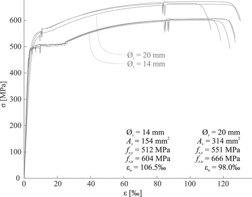
20 mm bar. Two diameters of reinforcement had to be used to produce the two different geometries (i.e. rectangular and optimised cross-section). The stress-strain behaviour of both diameters was tested in direct tension on at least three samples. The dynamic values of the yield stress (
), the ultimate stress (
) and the ultimate strain (
) are shown in Figure . The yield stress of the
20 mm reinforcing bar was around 7% higher than that of the
14 mm reinforcing bars. The static values of the stresses were 7% and 5% less for
14 mm and
20 mm reinforcing bars, respectively. In both cases, the reinforcing bars were produced with threaded ends to anchor them behind steel plates (see Figure ).
Figure 2. Stress-strain relationships and characteristic values of the reinforcing bars used in the experimental campaign.
3.2.3. Fibres
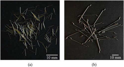
Two types of fibres were used in this study (see Figure ). Short straight steel fibres with a length of 6 mm, a diameter of 0.16 mm, a slenderness of 40 and a nominal tensile strength of 3000 MPa (Dramix OL 6/.16) were added in a concentration of either 0.3% (beams R-C-SF-03 and R-E-SF-03) or 0.7% (beam R-E-SF-07) to the concrete together with the accelerator and mixed right before casting. In the beams R-E-IF-03 and O-E-IF-06-RV, end-hooked fibres of the type Dramix 3D 65/35 with a length of 35 mm, a diameter of 0.55 mm, a slenderness of 65 and a nominal tensile strength of 1345 MPa were manually added between the layers of cast concrete. Since the fibres were delivered in glued bundles, they first had to be washed and dried to remove the glue and afterwards weighed for every layer of fibres.
Figure 3. Steel fibres used in this study: (a) short steel fibres; (b) end-hooked fibres.
3.3. Production
Three of the beams were horizontally cast inside a formwork. The remaining beams were produced using the Eggshell process and set up as described by Burger et al. (Citation2020). A six-axis robotic arm with a custom-developed filament extruder was used for the 3D printing process of the ultra-thin plastic formwork. The generation of the robotic tool path was done using the open-source slicing software COMPAS SLICER (Mitropoulou and Burger Citation2020).
The production consisted in the following steps:
| (1) | Mixing a large batch of retarded (i.e. delayed hydration) concrete. | ||||
| (2) | 3D printing of the ultra-thin plastic formwork (Figure (a)). | ||||
| (3) | Weighing a small batch of retarded concrete. | ||||
| (4) | Adding accelerator and, where applicable, short fibres to the small batch and mixing using a planetary mixer. | ||||
| (5) | Casting the accelerated concrete into the formwork (Figure (b)) forming a layer of 20 mm. | ||||
| (6) | In case of aligned interlayer fibres: Addition of fibres on top of the cast concrete (Figure (c)). | ||||
| (7) | Repetition of Steps 2–6 until the full height of the beam is reached. | ||||
| (8) | Covering the finished beam using a plastic foil and leaving them in the laboratory. | ||||
| (9) | Removing the plastic foil and the formwork one week before testing. | ||||
Figure 4. Fabrication process of a rectangular beam with aligned interlayer fibres: (a) Step 2: 3D printing of the formwork, (b) Step 5: Casting a layer of accelerated concrete; (c) Step 6: Manually placing and aligning interlayer fibres; (d) layout of the aligned fibres between the layers of cast concrete (R-E-IL-03).
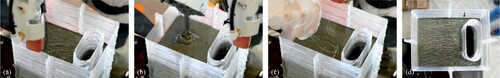
The beams were fabricated in vertical position. The filament height used for printing the plastic formwork was 1.5 mm, with a width of 2 mm and a printing speed of 30 mm/s. The total fabrication time of one beam amounted to 4 hours and 20 minutes. A layer of accelerated concrete (690 g or 0.3 L of retarded concrete with 7.4 g of accelerator) was cast approximately every 6.5 minutes after 20 mm of formwork height had been printed. 20 mm of the outer formwork were printed first, after which 20 mm of the inner void were printed to reduce travel time between the outer formwork layer and the inner void. The added concrete was self-compacting. Therefore, a high casting quality could be achieved without additional vibration. For the addition of the fibres, the fibres were either mixed with the accelerated concrete right before casting (i.e. short fibres), or the fibres were aligned according to the layout shown in Figure (d). The orientation of the fibres was chosen in the direction of occurring tensile stresses due to the applied shear forces. The aligned fibres were weighed separately and added manually between each casting step (i.e. in total 44 layers of fibres). The maximum allowed time to place the fibres was determined by the casting intervals (i.e. 6.5 minutes) to ensure the same production speed as the other beams produced with Eggshell.
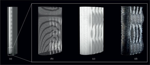
Beam R-E-RV featured an inner void that was not completely straight but was designed to provide a rough interface between the concrete cast into the beam and the grout cast into the void. The roughness was provided to enhance the shear transfer at the construction joint between the plastic and the surrounding concrete. A series of sinusoidal undulations were on the upper side of the void to achieve this roughness (Figure ).
Figure 5. Geometry of the rough void: (a) Complete void geometry where the rectangle indicates the section shown in the following illustrations; (b) visualisation of printing tool path; (c) Visualization of the rough void; (d) 3D printed section of the rough void (printed separately for this illustration).
After production, the outside formwork was removed with the aid of a hot air gun and pliers. After slightly heating the formwork with the hot air gun, the formwork can be peeled off in pieces. After demoulding, the longitudinal reinforcement was placed inside the void and fixed behind two steel plates. These anchor plates had a thickness of 40 mm, a height of 60 mm and a width of 120 mm. The formwork of the inner void was left in place, resulting in a construction joint with two plastic-concrete interfaces similar to the plastic duct of a prestressing tendon. The reinforcing bars were fastened by applying a torque of 30 Nm to ensure that the steel plates stayed in place during casting. The steel plate had an additional hole between the two openings for the reinforcing bars on one side. This additional hole was used for grouting the void in an upright position. The surface of the beams was uneven due to the layering of the plastic filament and small deformations of the formwork during production. Therefore, the areas above the supports and below the load application were ground to ensure planar surfaces for the support reactions and applied loads, respectively. Furthermore, one side face of the beams was ground, painted white and speckled in black for applying DIC instrumentation. For the cast beams, the load application area on top was also ground. For the side, only painting and speckling were needed.
3.4. Test set up and instrumentation
The beams were tested in a 4-point bending configuration in a universal testing machine (Walter&Bai) with a maximum loading capacity of 100 kN. The beams spanned over 860 mm, and the load application points were 70 mm apart (see Figure ). The loading was deformation controlled with a speed of 0.005 mm/s up to 1 mm deformation to cover the initial uncracked state. Afterwards, the speed was increased to 0.01 mm/s up to the failure of the beams.
The displacement and strain fields of one side of each beam were tracked with a 3D-DIC system (Mata-Falcón et al. Citation2020). The system was composed of two FLIR Grasshopper3 12.3 MP monochrome cameras, working at a frequency of 1 Hz and positioned at a distance of 1.6 m to the specimen's surface. The baseline of 0.7 m between the two cameras resulted in a stereo angle of 25. Lenses with a focal length of 25 mm (Quioptic MeVis-C 1.6/25) were used, which allowed a field of view of
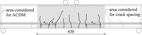
mm at an average scale of 0.23 mm/pixel (i.e. the entire side face of the beam could be monitored). The applied speckles had a size of approximately 2 mm, corresponding to ca. 9 pixels. The correlation was carried out with the commercial software VIC-3D (Correlated Solutions Citation2014) using a subset size of 29 px, a step size of 2 px and a strain filter size of 11. The correlated data was used to generate the load-deformation curves. In addition, the measured full-field displacement and strain fields were used as an input for the Automated Crack Detection and Measurement (ACDM) approach (Gehri, Mata-Falcón, and Kaufmann Citation2020, Citation2022). This approach results in detailed measurements of crack patterns and kinematics. The mean bending crack spacing
was computed according to Figure over the region with stabilised cracking at failure. The cracking load
is defined as the load in which the first detected bending crack reaches an opening of 0.01 mm.
Figure 6. Approach for measuring the mean bending crack spacing.
4. Beams with rectangular geometry: results and discussion
4.1. Overview of results
Figure shows the load-deformation curves, and Figures and depict the crack patterns at 80% and 100% of the peak load of all tested beams with a rectangular cross-section. Table provides information about the cracking load
and its associated concrete flexural tensile strength
, as well as the mean crack spacing
(see Section 3.4), peak load
, mid-span deflection at peak load
, failure type and concrete properties. The results of the beams without shear reinforcement are discussed in Section 4.2, while the behaviour of the beams including steel fibres as shear reinforcement are analysed in Section 4.3.
Figure 7. Load-deformation behaviour of all tested beams with a rectangular cross-section. The solid circles show the peak load and deformation recorded in Table and the crosses highlight the collapse.
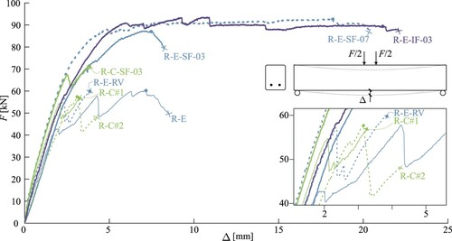
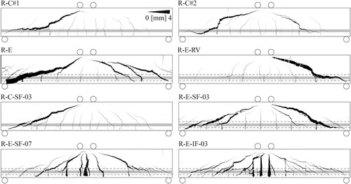
Figure 8. Crack patterns with line width proportional to the crack opening computed with ACDM (Gehri, Mata-Falcón, and Kaufmann Citation2020) at 80% of the peak load.
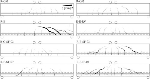
Figure 9. Crack patterns with line width proportional to the crack opening computed with ACDM (Gehri, Mata-Falcón, and Kaufmann Citation2020) at the peak load.
4.2. Behaviour of beams without shear reinforcement
The testing campaign's lowest peak loads (57 and 58 kN) were reached, with similar behaviour, by the two cast reference beams (R-C#1 and R-C#2) that did not contain any shear reinforcement. The main difference between the two responses was the significantly lower stiffness of R-C#2. This difference was caused by the air entrapment during casting of R-C#2 (see Section 3.2.1), which weakened its compression zone. At 80% , both beams showed a similar crack pattern with multiple and closely spaced bending cracks (
of 55 and 66 mm). For both beams, a first shear crack formed and stabilised. However, the formation of a second shear crack, in the other shear span of the beams, triggered a brittle failure. This shear crack is not visible for R-C#1 in Figure since there was no more correlation possible after the failure (see Figure ). The critical shear crack propagated along the reinforcement from the left support, from where it transitioned into the crack towards the load application (see Figure ). This behaviour is typically observed in concrete beams without shear reinforcement (e.g. Campana et al. Citation2013).
Figure 10. View of three selected beams after failure.
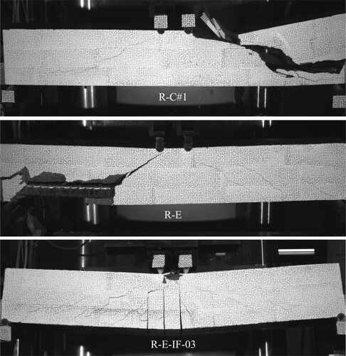
The effect of the Eggshell production and the inclusion of the void with grouted reinforcement can be studied by comparing the reference beams to the beam with no shear reinforcement produced with Eggshell (R-E). This beam had a similar maximum load (ca. 60 kN) but experienced a different crack behaviour (see Figure ) and stiffness. Several shear cracks formed in the right shear span of specimen R-E at a considerably lower load (40 kN) than in the cast beams, and the bending crack spacing was almost double (101 mm). While the analysis of the crack behaviour (discussed in Section 4.4) shows a local reduction of the concrete tensile strength in the interlayers of the Eggshell specimens, this effect seemed to affect the global behaviour much less than the construction joint with the plastic void: the reduced tensile strength would rather have caused a reduction of the crack spacing (Mata-Falcón, Bischof, and Kaufmann Citation2019). Once the shear cracks in the right shear span of beam R-E stabilised, the load could be further increased. At around 58 kN, a large shear crack opened in the left shear span of the beam (Figure ), resulting in a sudden load drop. After this drop, the load could again be increased up to the peak load of 60 kN. This additional loading might have been enabled by a stabilising effect of the reinforcement anchorage plates. Figure shows the failed beam. In this case, the critical shear crack propagated along the void and extended straight towards the load application points. During failure, the concrete around the void spalled, exposing the void. Again, this behaviour indicates the weak bond at the construction joint.
The peak load for the beam with a rough void (R-E-RV) was almost identical to that of the beam with a straight void (R-E). However, formation of the early shear cracks could be avoided, and more bending cracks formed ( mm). This behaviour indicates that the shear transfer at the construction joint could be improved by increasing the roughness of the void. However, the bending crack spacing was still not as small as in the cast samples. Therefore, the shear transfer of the rough construction joint might still not have reached the same strength as the material itself in a cast sample. Since only one specimen was tested, further investigation on the stress transfer at the construction joint between the beam and the grouted void is needed.
4.3. Behaviour of beams with fibres as shear reinforcement
The behaviour of the four beams without shear reinforcement indicates that the influence of the production technique (i.e. casting or Eggshell process) on the peak load and the failure mode is small and that shear reinforcement is needed to enable a ductile and significantly hardening response after the formation of shear cracks. By adding short fibres with a fibre content of 0.3% to the concrete of the cast sample (R-C-SF-03), the failure load could be increased by roughly 20%. At 80% of the peak load, a large number of bending cracks had formed ( of 56 mm), similar to the spacing in the cast samples without fibres. At around 68 kN, a first shear crack formed, followed by a small load drop. Afterwards, the crack stabilised, and the load could be increased up to 71 kN where a shear crack opened in the other shear span of the beam leading, to an abrupt failure.
When the same amount of short fibres was added during the Eggshell production (R-E-SF-03), the load could be further increased to almost 90 kN, and no load drops occurred during the formation of shear cracks. Since R-C-SF-03 was produced horizontally and R-E-SF-03 vertically, the effect of the flow of the concrete casting on the fibres might have caused this difference in peak load. During casting, fibres tend to align in the direction of flow (Stähli, Custer, and van Mier Citation2008). Therefore, the main fibre orientation of the cast samples was aligned to the longitudinal reinforcement while it was perpendicular for the Eggshell production. Since orienting the fibres transversely is more favourable for resisting shear, the Eggshell produced beam could be expected to reach a higher load. Compared to the Eggshell produced beams without fibres, the crack spacing could be reduced. Due to the addition of fibres, micro-cracks at the construction joint might have been reduced (Zollo Citation1997), leading to an improvement of the shear transfer along the joint and to an increased bond of the tension chord. The addition of fibres did, however, not compensate for the weak interface fully since the crack spacing was still considerably larger than in the cast beams. The specimen R-E-SF-03 still failed in shear, despite that the crack propagation after peak load was more stable, as indicated by the additional deformations after peak load. The behaviour resembles the fibre pull-out also observed in Gebhard et al. (Citation2021).
By increasing the fibre content to 0.7% (R-E-SF-07), a shear failure could be avoided. This increase in fibre content resulted in a stabilisation of the shear cracks, and with increasing load, yielding of the longitudinal reinforcement was reached. After the onset of yielding, the deformations localised in the bending cracks below the load application points. A peak load of 93 kN could be reached, and failure occurred due to concrete crushing in the compression zone of the beam. The load was increased by 55% compared to the sample produced with Eggshell without fibres.
A similar load and failure mode could be reached for the beam reinforced with long end-hooked fibres at a content of 0.3% between the layers (R-E-IF-03). Ultimately the beam failed due to concrete crushing in the compression zone, similarly to beam R-E-SF-07. The failed compression zone can be seen in Figure .
From the results of the fibre reinforced beams, it can be concluded that the effectiveness of the fibres varies. For the same fibre type (i.e. short fibres) but different orientation during production (i.e. R-C-SF-03 and R-E-SF-03), the peak load and, therefore – assuming that there was no other influence – the effectiveness of the fibres increased by 23%. A further increase was reached by more than doubling the fibre content (i.e. R-E-SF-03 and R-E-SF-07). However, since the failure type of the two beams was different (i.e. shear and bending), no direct comparison of the fibre effectiveness is possible. The same holds for the different fibre types and placement at the same concentration (i.e. R-E-SF-03 and R-E-IF-03). Here, the effectiveness could also be increased. This increase was possible due to the beneficial alignment and the increased slenderness of the fibres. The accurate assessment of the difference in fibre effectiveness requires further studies. Overall, the performance of the beam with interlayer fibre reinforcement (R-E-IF-03) showed the highest efficiency. The beam was able to reach yielding of the longitudinal reinforcement with less than half the fibre content than the beam with conventional fibre reinforcement (i.e. 0.3 and 0.7%).
4.4. Crack behaviour
For future mass-market applications, it is necessary to predict the crack behaviour of the produced structures to ensure serviceability requirements. Hence, bending cracks and crack spacing are important parameters giving insights into the structural behaviour. The crack spacing was already discussed in Sections 4.2 and 4.3. Therefore, the focus of this section lies in the formation of the bending cracks, their opening and modelling approaches.
For all Eggshell produced beams, the bending cracks seemed to originate and progress between the concrete layers. However, due to the influence of shear loads, the cracks ended crossing these layers. This behaviour reveals a weakening of the concrete tensile strength at the interlayer, which the material characterisation tests could not properly capture (see comment in Section 3.2.1). The most pronounced layering effect on the crack pattern could be observed for the beam with interlayer fibre reinforcement. Here, the orientation of the bending cracks did follow the layers more clearly compared to the samples with fibres in the mix (see Figure ). This behaviour indicates that the placement of the fibres in the layer might harm this interlayer strength. This reduction of the interlayer strength is most likely caused by the fibres being in the same layer. Therefore, the concrete-concrete interface is reduced in this area, and transverse tensile stresses are caused by fibre activation.
The cracking load of the beams was subject to a large scatter (see Table ). These variations seem to be related to differences in (i) the curing time and (ii) the production process. The two beams with the longest curing time (i.e. R-E and R-E-SF-07 (see Section 3.2.1)) had the highest tensile strengths and cracking loads. It can be seen that the stress at cracking was in the same order of magnitude as the measured tensile strength. However, another beam also produced with Eggshell and having a similar tensile strength (e.g. R-E-SF-03), but tested at a younger age had a much lower cracking load. This behaviour indicates that the age of the specimens affects the initial stress state presumably due to the fastening of the longitudinal reinforcement. The reinforcement was fastened with a small torque that introduced a slight precompression in the specimen and delayed cracking. The 14 days old samples are expected to creep much more than the half a year old ones. Hence, relaxation will absorb a major part of the initial precompression, reducing the cracking loads. However, this slight prestressing is not expected to affect the failure load. When comparing among the youngest samples, the Eggshell production is observed to reduce the cracking load significantly: in R-E-RV, R-E-SF-03 and R-E-IF-03, the maximum tensile stress at cracking is only ca. 30% of the material tensile strength
. These results are in line with the observations of Mata-Falcón, Bischof, and Kaufmann (Citation2019), which also predicted layering processing to produce more cracks with smaller openings. However, the crack spacing and opening in the present study seemed to be governed by the bond in the construction joint rather than the weaker strength between the layers (see Section 4.1).
In the following, the crack behaviour (crack spacings and crack openings) is predicted and compared to the experimental results. A comparison of several methods to estimate the crack behaviour is given in Galkovski, Mata-Falcón, and Kaufmann (Citation2022). The equilibrium approach of Pfyl (Citation2003) and the simplified bond behaviour of the Tension Chord Model by Marti et al. (Citation1998) (i.e. before the onset of yielding) are applied in this study to predict the crack spacing. For this calculation, average material properties of all specimens (see Section 3.2.1) are considered, resulting in a predicted crack spacing between 23 and 46 mm. Table shows that the crack spacings in the conventionally cast specimens are in relatively good agreement with the predicted value. However, the crack spacings of the Eggshell produced beams are highly underestimated. This underestimation was expected since the model does not consider the weakening introduced by the construction joint between the printed void and the surrounding concrete. This effect might be considered by simply reducing the bond of reinforcement considered in the model to around
. This approach would lead to a crack spacing in the specimens with a void between 46 and 92 mm, in the range of the spacings observed in the experimental campaign. Proper calibration of this parameter would require a more extensive testing series.
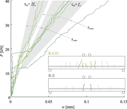
Figure shows the crack opening of the bending cracks near the load application points at the depth of the reinforcement for the two beams R-E and R-C#1. The beams were chosen since they show the two extremes of crack spacing without fibres as shear reinforcement. The crack opening is shown up to a force of 40 kN. After reaching that force, shear cracks occurred, which influenced the bending crack opening. The grey areas in Figure show the predicted range of crack widths versus applied loads computed with the model mentioned above for and
. The five bending cracks of the cast beam without a void (i.e. green lines in Figure ) could be divided into two groups. Two of the cracks fell well into the range of predicted crack widths for
while the other three were in the range for
. For the two analysed cracks of R-E (i.e. blue curves in Figure ) the crack opening was considerably larger. At the onset of cracking, the bending cracks opened instantly, and subsequently widened with a fairly linear slope in the order of magnitude predicted for a bond stress of
. This behaviour again indicates the reduced bond resulting from the construction joint at the void. For further applications of Eggshell with this reinforcement approach, an increased bond (e.g. by increasing the roughness all around the void similar to a corrugated duct of a prestressed tendon) should be ensured. Only if these deficiencies at the construction joint are reduced or solved, a positive impact on the crack spacing and width due to the layered production might be observed (see Mata-Falcón, Bischof, and Kaufmann Citation2019). For simple geometries, the formwork could also be printed as a whole, the reinforcement added afterwards, and the concrete cast as shown for the fabrication of the Future Tree Column (Burger et al. Citation2020). However, as mentioned in the Introduction, this approach is limited to simple geometries and cannot cover the entire design space of the Eggshell technology. Furthermore, the construction speed would not significantly be improved since the hardening of the accelerated concrete (i.e. reduction of hydrostatic pressure) is the dominant factor for the vertical build-up rate.
Figure 11. Crack opening versus applied force for R-C#1 and R-E. The crack lines were smoothed with a moving average with a span of 5. The grey area shows the expected crack opening for a bond stress and
in the range of the minimum and maximum theoretical crack spacing (
and
).
5. Optimised beam
5.1. Design
Based on the results of the test series with rectangular cross-section, an optimised beam was designed (see Figure (a)). The objective of this design was to exploit the geometric freedom provided by Eggshell to reduce the use of concrete while achieving similar mechanical performance. The concept behind the optimisation was to use simple mechanical considerations to achieve significant material savings without complex optimisation tools. Therefore, the cross-section was reduced to a T-shape. The cross-section of the rectangular beams was considered as the maximum boundary box of this T-shape. The compression flange was designed to withstand a compression equal to the tensile capacity of the reinforcement. The width of the flange was taken as the width of the rectangular beams (i.e. 120 mm), and the height resulted in 25 mm. The web was reduced to a third of the rectangular thickness (i.e. 40 mm). The shear transfer was approximated with the insights of the experimental campaign of the rectangular beams (see below). The design of the lower part of the cross-section accommodated the void for the post-installation of the longitudinal reinforcement. It needed to be ensured that the void was large enough to add and grout the longitudinal reinforcement with sufficient concrete cover around the void. The volume was further reduced in the longitudinal direction with a circular shape (radius of 1.7 m). This shape was chosen to facilitate the post-installation of the longitudinal reinforcement while optimising the geometry for the bending moments. At mid-span, the beam had the same height and static depth as the rectangular beams. The overall volume could be reduced to 52% compared to the rectangular beams. The reinforcing bar was bent according to the circular shape. Its diameter was 20 mm to match the steel cross-section of the two
14 mm reinforcing bars used in the series of rectangular beams (see Figure ). The void was chosen to be rough to ensure a proper bond between the void and the concrete. As shear reinforcement, aligned interlayer fibres were chosen as they showed the best load-deformation behaviour in the rectangular series with the lowest fibre amount. The fibres were orientated vertically in the web and horizontally in the flange (Figure (a)). The total amount of fibres was kept the same as for the rectangular beam with 0.3%. Since the beam volume was reduced by almost 50%, the fibre content for the optimised beam increased to 0.6%.
Figure 12. Geometry and test set up of the optimised beam (dimensions in [mm]).
![Figure 12. Geometry and test set up of the optimised beam (dimensions in [mm]).](/cms/asset/1695594e-ce65-4055-9e63-4240172700ea/nvpp_a_2041873_f0012_ob.jpg)
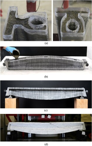
Figure 14. Different steps from fabrication to testing of the optimised beam: (a) Impressions from the production process and the fibre alignment; (b) Grouting of the void; (c) The final beam; (d) Failed beam after testing.
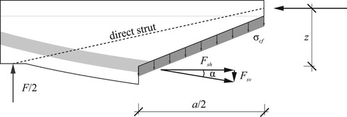
For the structural pre-design of the optimised beam, some assumptions based on the results of the rectangular beams and previous experimental studies were made. For the optimised beam, it was assumed that three main mechanisms transfer the shear forces, (i) the fibre reinforcement, (ii) other shear transfer mechanisms (mainly direct strut) and (iii) the vertical contribution of the longitudinal reinforcement. The transfer mechanisms are summarised in Figure . A study on aligned interlayer fibre reinforcement with the same fibre type and concentration as shear reinforcement for 3D printed beams (Gebhard et al. Citation2021) showed that the fibres transferred around 70% of the total shear force. Furthermore, it was shown that doubling the fibre concentration in the same layer results in a load increase of around 50% (Gebhard et al. Citation2021, Citation2021?). The beam R-E-IF-03 was able to transfer at least 45 kN in shear (i.e. ). Therefore, assuming that the fibres carried 70% of the total shear force, the fibres in beam R-E-IF-03 transferred around 32 kN, while the remaining 13 kN were transferred by other mechanisms (e.g. direct strut). For the optimised beam, the fibre concentration was doubled (i.e. 50% increase in fibre contribution), but the web width was reduced to a third. Therefore, the shear transfer of the fibres of the optimised beam was estimated to be at least 16 kN (
). Assuming that the other shear transfer mechanisms (i.e. direct strut) are unaffected by the change in geometry, a further 13 kN could be transferred. In addition to the shear transfer mechanisms of the rectangular beams, the optimised beam had a contribution from the inclination of the longitudinal reinforcement, whose vertical component contributes to resisting shear forces. This contribution is zero at mid-span and maximum at the supports. As a first estimation, the contribution was considered at half of the shear span a=395 mm (i.e. a/2). Assuming that the compressive force acts at the centre of the flange, a total force F of 94 kN needs to be applied to yield the reinforcement at mid-span, and at half the shear span, the moment is
while the inner lever z is 92 mm. Hence, the horizontal part of the force in the reinforcement
kN. With an inclination
, the vertical component of the force
is 14 kN. The total shear transfer of the optimised beam is thus assumed to be in the order of 43 kN, and the expected performance is in the same order as the rectangular beam. However, this performance is achieved with a concrete material reduction of almost 50%.
Figure 13. Shear transfer model for the optimised beam. represents the stresses transferred by the fibres.
5.2. Production and testing
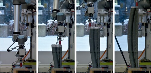
The optimised beam was produced vertically (see Figures and (a)), similar to the rectangular beams. The production parameters and curing conditions were kept identical to the rectangular beams. The total production time was also similar. Since only one reinforcing bar was used and the space of the void was limited, the filling strategy for the void needed to be changed. Three openings along the bottom of the beam were provided to this end. Two openings were printed close to the support to ensure high grouting quality in this region and one at mid-span. The void was filled with the beam laying horizontally on the compression flange (see Figure (b)). The resulting optimised beam can be seen in Figure (c). For testing, the same steps as for the rectangular beams were taken (see Section 3.3), and the test set up and instrumentation were identical (see Section 3.4).
Figure 15. Time lapse of the production process of the optimised beam.
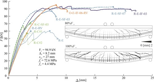
5.3. Results and discussion
Figure shows the load-deformation behaviour and the crack patterns of the optimised beam (O-E-IF-06-RV). The initial stiffness of the beam was lower than that of the rectangular beams. This decreased stiffness was caused due to the material reduction. At 80% of the peak load, the beam showed a crack pattern with closely spaced bending and multiple shear cracks. The average crack spacing immediately before failure was 27 mm. This crack pattern reflected the higher degree of utilisation of the longitudinal reinforcement resulting from the optimisation. Furthermore, the bond between the void and the concrete seemed to be significantly higher than that of the rectangular beams produced with a void. The peak load was almost 95 kN, i.e. higher than the maximum capacity of all rectangular beams. This difference is likely to be caused by the higher yield stress of the 20 mm bar, around 7% higher than the
14 mm bars used for the rectangular beams (see Figure ). The beam failed in shear before significant yielding of the longitudinal reinforcement, probably due to fibre pull-out in the thin part of the web. Therefore, it failed with deformations below the beams R-E-SF-07 and R-E-IF-03. The resulting shear force of 47.5 kN coincided well with the prediction of 43 kN (see Section 5.1). This agreement indicates that the assumptions made for the pre-design are valid. However, further studies are required to fully understand the contribution of the various shear transfer mechanisms for optimised beams with interlayer fibre reinforcement.
Figure 16. Load deformation behaviour of all samples and the crack patterns of the optimised beam at 80 and 100% of peak load.
Even though the deformation capacity of the optimised beam was limited and a bending failure could not be reached, the experiments showed the potential of combining innovative reinforcement solutions with optimised geometries to unlock the potential of Eggshell for the fabrication of efficient concrete structures. Further research is required to verify this full potential. Specifically, fabrication on a larger scale is needed. This increase in scale might have various implications on the fabrication process and the structural behaviour. On the one hand, the printing time of a larger element will be longer, provided the same 3D printing set up is used. The increase in printing time could result in a slower casting rate, potentially leading to cold joints between the layers of concrete. Therefore, to scale up the process, 3D printing equipment with a higher flow rate might be required to ensure a synchronised printing and casting process. On the other hand, a larger scale will allow for more tolerances for the conventional reinforcement and simplify the grouting process. Finally, while in the current project, the fibres were added manually, the fibre placement would need to be automated and synchronised with the digital casting process for large scale applications. Alternatively, it could also be imagined that the fibres are mixed with the concrete right before casting to overcome pumping constraints. The addition of the fibres right before casting might become especially relevant if the casting process is changed from a batch-by-batch approach to a continuous digital casting process (Lloret-Fritschi et al. Citation2020).
6. Conclusion
Digital fabrication with concrete has the potential to have a lasting positive impact on the construction industry. As one of these technologies, the Eggshell fabrication process allows for the production of complex geometries by 3D printing a thermoplastic formwork with the simultaneous casting of set-on-demand concrete. The Eggshell casting process is batch-by-batch what allows using several reinforcement strategies, such as pick and place of small reinforcing bars in the interface, post-installed reinforcement inside internal channels, aligned fibre reinforcement and conventional fibre reinforcement. This paper focussed on the structural performance of reinforcement strategies which result in a predictable ductile response (i.e. conventional reinforcement) but do not limit the geometric flexibility (i.e. fibres). To this end, an experimental campaign of eight beams with rectangular cross-section showed that:
The use of longitudinal reinforcement results in predictable structural behaviour.
The printing of voids is a feasible strategy to allow the addition of longitudinal reinforcement after the production.
The bond at the construction joint between the void and the concrete can be increased by enhancing the roughness of the void but to reach the same performance as bond without the void, the roughness needs to be increased even further.
The addition of fibres to the concrete mix enhances the load-bearing capacity.
The placement of aligned long end-hooked fibres between the layers of concrete results in a higher efficiency of the fibre usage compared to conventional fibre reinforcement.
The production process (i.e. layering and inclusion of the void) influences the formation of the bending cracks but has little influence on the global structural behaviour and the shear crack pattern.
From these findings, the reinforcement strategy of combining aligned interlayer fibre reinforcement as shear reinforcement with conventional longitudinal reinforcement placed in a grouted void is identified as the most efficient solution.
The findings from these regular beams were applied to the design and production of an optimised beam. The production and testing of this beam showed that:
The Eggshell fabrication process is capable of increasing the complexity of produced geometries without extra cost nor time.
The findings from the structural tests on simple geometries are applicable for complex geometries.
Material savings of almost 50% can be achieved by optimising a standard concrete beam design.
Since the findings of this study are generally based on a single experiment for each configuration, further production and testing of complex geometries at a larger scale are needed to validate these findings and thoroughly verify the applicability of the Eggshell fabrication with the presented reinforcement strategy. Special attention should be given to the bond at construction joints of voids.
Open-access data repository
The data for the present publication can be found under the following DOI: https://doi.org/10.3929/ethz-b-000518546
Acknowledgments
The authors gratefully acknowledge the support of the ETH Zurich students Alessia Medici, Matthias Füchslin, Armin Bratschi and Marc Muggli in the production, preparation and testing of the beams. Debrunner Acifer are thanked for providing the reinforcing bar for the optimised beam. The authors would like to express their gratitude for the support of the technical teams of the IBK Structures Lab, the NCCR dfab Robotic Fabrication Lab, and the IfB Concrete Lab at ETH Zurich.
Disclosure statement
No potential conflict of interest was reported by the author(s).
Additional information
Funding
Notes on contributors
Lukas Gebhard
Lukas Gebhard is a civil engineer interested in digital fabrication with concrete focussing on innovative reinforcement strategies. In 2018, he completed his master's degree in civil engineering at ETH Zurich with distinction. After his graduation, he started his doctorate under the supervision of Prof. Kaufmann at the Chair of Concrete Structures and Bridge Design. The research is part of the NCCR Digital Fabrication and investigates the structural behaviour of reinforced and digitally fabricated concrete elements. In 2021, he was a Research Fellow at the University of Naples Frederico II.
Joris Burger
Joris Burger has studied Architecture in the Netherlands, Sweden and Japan, after which he completed his Master of Science in Building Technology (with distinction) at Delft University of Technology. During his studies, he focussed on digital fabrication, computational form-finding and façade design. Furthermore, he has gained professional experience working for the design, engineering and manufacturing company Octatube in Delft, the Netherlands. He completed his MSc thesis in collaboration with the chair of Architecture and Digital Fabrication (Prof. Fabio Gramazio, Prof. Matthias Kohler) before starting as a PhD Researcher within the NCCR Digital Fabrication.
Jaime Mata-Falcón
Jaime Mata-Falcón is a senior assistant at the Chair of Concrete Structures and Bridge Design of ETH Zurich, where he joined as a postdoctoral researcher in 2015. After he had worked for two years as a structural engineer, in 2009, he completed his master's degree in civil engineering at the Polytechnic University of Valencia, Spain. He then specialised himself with a master's degree in concrete engineering. In 2015, he obtained his doctorate from the Polytechnic University of Valencia with a dissertation on the crack behaviour of dapped-end concrete beams. During his doctorate, Jaime also worked in the Structural Concrete Laboratory at EPF Lausanne on the domain of Elastic-Plastic Stress Fields. In April 2016, Jaime Mata-Falcón joined the NCCR Digital Fabrication to address the structural integrity of the reinforced concrete technologies.
Ena Lloret Fritschi
Ena Lloret Fritschi is an architect with an interest in shaping concrete without the need for traditional formwork. She is currently a postdoctoral researcher in a bridge position between the Chair of Gramazio Kohler Research and the Chair of Physical Building Chemistry of Prof. Robert Flatt. Her work is embedded in the research strand Mouldless Shaping with concrete within the DFAB or the NCCR, ETH, where she guides PhD students and coordinates projects. Ena successfully defended her PhD Dissertation on Smart Dynamic Casting: A Digital fabrication method for concrete structures on June 16, 2016. In 2012 Smart Dynamic Casting received the Concrete Innovation Award at the Concrete Innovation Conference in Oslo and was amongst the 5 finalists for the SPARK award at the ETH Zurich.
Fabio Gramazio
Fabio Gramazio is an architect with multidisciplinary interests ranging from computational design and robotic fabrication to material innovation. In 2000, he founded the architecture practice Gramazio Kohler Architects in conjunction with his partner Matthias Kohler, where numerous award-winning designs have been realised. Current projects include the design of the NEST building of Empa and Eawag, a future living and working laboratory for sustainable building construction. Opening also the world's first architectural robotic laboratory at ETH Zurich, Gramazio Kohler's research has been formative in the field of digital architecture, setting precedence and de facto creating a new research field merging advanced architectural design and additive fabrication processes through the customised use of industrial robots. This ranges from 1:1 prototype installations to the design of robotically fabricated high-rises. The recent research is outlined and theoretically framed in the book ‘The Robotic Touch: How Robots Change Architecture’ (Park Books, 2014). Fabio Gramazio joined the NCCR Digital Fabrication in 2014 as a principal investigator.
Matthias Kohler
Matthias Kohler is an architect with multidisciplinary interests ranging from computational design and robotic fabrication to material innovation. In 2000, he founded the architecture practice Gramazio Kohler Architects in conjunction with his partner Fabio Gramazio where numerous award-wining designs have been realised. One of the latest projects was the design of the NEST building of Empa and Eawag, a future living and working laboratory for sustainable building construction. Opening also the world's first architectural robotic laboratory at ETH Zurich, Gramazio Kohler's research has been formative in the field of digital architecture, setting precedence and de facto creating a new research field merging advanced architectural design and additive fabrication processes through the customised use of industrial robots. This ranges from 1:1 prototype installations to the design of robotically fabricated high-rises. The recent research is outlined and theoretically framed in the book ‘The Robotic Touch: How Robots Change Architecture’ (Park Books, 2014). Matthias Kohler initiated the NCCR Digital Fabrication and was its Director from its official foundation in the summer of 2014 until the summer of 2017. He now works as one of the NCCR's principal investigators.
Walter Kaufmann
Walter Kaufmann is the Chair of Structural Engineering (Concrete Structures and Bridge Design) at ETH Zurich. He is a Lead Principal Investigator in the Swiss National Centre of Competence in Research (NCCR) Digital Fabrication and presides the Swiss Concrete Code Commission. His research focuses on innovative structures, the load bearing and deformation capacity of concrete structures, the assessment of the structural safety of existing structures, and digital fabrication methods. He obtained his degrees from ETH Zurich in 1992 (dipl. Bau-Ing.) and 1998 (Dr. sc. techn.), respectively. Prior to joining ETH Zurich in 2014, he was active in industry for more than 15 years, working mainly in Spain and Switzerland. During this time, he participated successfully in many bridge design competitions, directed numerous structural engineering projects for buildings and bridges, and was involved in a large number of expert appraisals.
References
- Asprone, Domenico, Costantino Menna, Freek P. Bos, Theo A. M. Salet, Jaime Mata-Falcón, and Walter Kaufmann. 2018. “Rethinking Reinforcement for Digital Fabrication with Concrete.” Cement and Concrete Research 112: 111–121. Accessed March 28, 2019. http://www.sciencedirect.com/science/article/pii/S0008884618300309.
- Burger, Joris, Ena Lloret-Fritschi, Fabio Scotto, Thibault Demoulin, Lukas Gebhard, Jaime Mata-Falcón, Fabio Gramazio, Matthias Kohler, and Robert J. Flatt. 2020. “Eggshell: Ultra-Thin Three-Dimensional Printed Formwork for Concrete Structures.” 3D Printing and Additive Manufacturing 7 (2): 48–59. Publisher: Mary Ann Liebert, Inc., publishers, Accessed November 10, 2020. https://www.liebertpub.com/doi/https://doi.org/10.1089/3dp.2019.0197.
- Burger, Joris, Ena Lloret Fritschi, N. Taha, Fabio Scotto, Thibault Demoulin, Jaime Mata-Falcón, Fabio Gramazio, and Matthias Kohler. 2020. “Design and Fabrication of a Non-Standard, Structural Concrete Column using Eggshell: Ultra-Thin, 3D-Printed Formwork.”.
- Campana, Stefano, Miguel Fernández Ruiz, Andrea Anastasi, and Aurelio Muttoni. 2013. “Analysis of Shear-transfer Actions on One-way RC Members Based on Measured Cracking Pattern and Failure Kinematics.” Magazine of Concrete Research 65 (6): 386–404. Publisher: ICE Publishing, Accessed May 15, 2020. https://www.icevirtuallibrary.com/doi/full/https://doi.org/10.1680/macr.12.00142.
- Chen, W. F. 1969. “Double Punch Test for Tensile Strength of Concrete.” 13.
- Correlated Solutions. 2014. “VIC 3D Software, Reference Manual v7.”.
- Favier, Aurélie, Catherine De Wolf, Karen Scrivener, and Guillaume Habert. 2018. A Sustainable Future for the European Cement and Concrete Industry – Technology Assessment for Full Decarbonisation of the Industry by 2050. Technical Report. ETH Zürich, EPFL.
- Galkovski, Tena, Jaime Mata-Falcón, and Walter Kaufmann. 2022. “Effective Reinforcement Ratio of RC Beams: Validation of Modelling Assumptions with High-Resolution Strain Data.” Structural Concrete (in press). doi:https://doi.org/10.1002/suco.202100739.
- Gebhard, Lukas, Joris Burger, Jaime Mata-Falcón, Ena Lloret, Fabio Gramazio, Matthias Kohler, and Walter Kaufmann. 2021. “Structural Design Possibilities of Reinforced Concrete Beams using Eggshell.” In Proceedings of the International fib Symposium of the Conceptual Design of Structures, edited by Corentin Fivet, Pierluigi D'Acunto, Miguel Fernández Ruiz, and Patrick Ole Ohlbrock, Attisholz Areal, 530. Switzerland: Féderation Internationale du Béton – International Federation for Structural Concrete.
- Gebhard, Lukas, Jaime Mata-Falcón, Ana Anton, Joris Burger, Ena Lloret-Fritschi, Lex Reiter, and Benjamin Dillenburger, et al. 2020. “Aligned Interlayer Fibre Reinforcement and Post-tensioning as a Reinforcement Strategy for Digital Fabrication.” In Second RILEM International Conference on Concrete and Digital Fabrication, edited by Freek P. Bos, Sandra S. Lucas, Rob J.M. Wolfs, and Theo A.M. Salet, RILEM Bookseries, 622–631. Cham: Springer International Publishing.
- Gebhard, Lukas, Jaime Mata-Falcón, Ana Anton, Benjamin Dillenburger, and Walter Kaufmann. 2021. “Structural Behaviour of 3D Printed Concrete Beams with Various Reinforcement Strategies.” Engineering Structures 240: 112380. Accessed April 29, 2021. https://www.sciencedirect.com/science/article/pii/S0141029621005307.
- Gebhard, Lukas, Jaime Mata-Falcón, Tomislav Markić, and Walter Kaufmann. 2021. “Aligned Interlayer Fibre Reinforcement for Digital Fabrication with Concrete.” In Fibre Reinforced Concrete: Improvements and Innovations, edited by Pedro Serna, Aitor Llano-Torre, José R. Martí-Vargas, and Juan Navarro-Gregori, RILEM Bookseries, 87–98. Cham: Springer International Publishing.
- Gehri, Nicola, Jaime Mata-Falcón, and Walter Kaufmann. 2020. “Automated Crack Detection and Measurement Based on Digital Image Correlation.” Construction and Building Materials 256: 119383. Accessed October 1, 2020. http://www.sciencedirect.com/science/article/pii/S095006182031388X.
- Gehri, Nicola, Jaime Mata-Falcón, and Walter Kaufmann. 2022. “Refined Extraction of Crack Characteristics in Large-scale Concrete Experiments Based on Digital Image Correlation.” Engineering Structures 251: 113486. Accessed November 12, 2021. https://www.sciencedirect.com/science/article/pii/S0141029621015893.
- Habert, G., S. A. Miller, V. M. John, J. L. Provis, A. Favier, A. Horvath, and K. L. Scrivener. 2020. “Environmental Impacts and Decarbonization Strategies in the Cement and Concrete Industries.” Nature Reviews Earth & Environment 1: 1–15. Publisher: Nature Publishing Group, Accessed September 23, 2020. https://www.nature.com/articles/s43017-020-0093-3.
- Jipa, Andrei, Mathias Bernhard, and Benjamin Dillenburger. 2017. “Submillimeter Formwork. 3D-Printed Plastic Formwork for Concrete Elements.” In TxA Emerging Design + Technology Conference, Austin, Texas, USA.
- Kaufmann, Walter, Jaime Mata-Falcón, and Ali Amin. 2019. “Compression Field Analysis of Fiber-Reinforced Concrete Based on Cracked Membrane Model.” ACI Structural Journal 116 (5): 213–224. Accessed May 11, 2020. http://www.concrete.org/Publications/InternationalConcreteAbstractsPortal.aspx?m=details&i=51716763.
- Kloft, Harald, Martin Empelmann, Norman Hack, Eric Herrmann, and Dirk Lowke. 2020. “Reinforcement Strategies for 3D-concrete-printing.” Civil Engineering Design 2 (4): 131–139. Accessed October 15, 2020. https://onlinelibrary.wiley.com/doi/abs/https://doi.org/10.1002/cend.202000022.
- Leschok, Matthias, and Benjamin Dillenburger. 2019. “Dissolvable 3DP Formwork.” In Ubiquity and Autonomy – Proceedings of the ACADIA Conference, Austin, Texas: The University of Texas at Austin.
- Lloret, Ena, Amir R. Shahab, Mettler Linus, Robert J. Flatt, Fabio Gramazio, Matthias Kohler, and Silke Langenberg. 2015. “Complex Concrete Structures: Merging Existing Casting Techniques with Digital Fabrication.” Computer-Aided Design 60: 40–49. Accessed January 25, 2022. https://www.sciencedirect.com/science/article/pii/S001044851400044X.
- Lloret-Fritschi, Ena, Timothy Wangler, Lukas Gebhard, Jaime Mata-Falcón, Sara Mantellato, Fabio Scotto, Joris Burger, et al. 2020. “From Smart Dynamic Casting to a Growing Family of Digital Casting Systems.” Cement and Concrete Research 134: 106071. https://linkinghub.elsevier.com/retrieve/pii/S0008884619316205.
- Marti, Peter. 1989. “Size Effect in Double-Punch Tests on Concrete Cylinders.” Materials Journal 86 (6): 597–601. Accessed October 6, 2020. https://www.concrete.org/publications/internationalconcreteabstractsportal.aspx?m=details&ID=2261.
- Marti, Peter, Manuel Alvarez, Walter Kaufmann, and Viktor Sigrist. 1998. “Tension Chord Model for Structural Concrete.” Structural Engineering International 8 (4): 287–298. Publisher: Taylor & Francis, Accessed July 11, 2020. https://doi.org/https://doi.org/10.2749/101686698780488875.
- Mata-Falcón, J., P. Bischof, and W. Kaufmann. 2019. “Exploiting the Potential of Digital Fabrication for Sustainable and Economic Concrete Structures.” In First RILEM International Conference on Concrete and Digital Fabrication – Digital Concrete 2018, edited by Timothy Wangler and Robert J. Flatt, RILEM Bookseries, 157–166. Cham: Springer International Publishing.
- Mata-Falcón, Jaime, Severin Haefliger, Minu Lee, Tena Galkovski, and Nicola Gehri. 2020. “Combined Application of Distributed Fibre Optical and Digital Image Correlation Measurements to Structural Concrete Experiments.” Engineering Structures 225: 111309. Accessed December 21, 2020. http://www.sciencedirect.com/science/article/pii/S0141029620339109.
- McKinsey & Company. 2016. “Imagining construction's digital future.”.
- Mechtcherine, Viktor, Richard Buswell, Harald Kloft, Freek P. Bos, Norman Hack, Rob Wolfs, Jay Sanjayan, et al. 2021. “Integrating Reinforcement in Digital Fabrication with Concrete: A Review and Classification Framework.” Cement and Concrete Composites 119: 103964. Accessed April 11, 2021. https://www.sciencedirect.com/science/article/pii/S0958946521000342.
- Menna, Costantino, Jaime Mata-Falcón, Freek P. Bos, Gieljan Vantyghem, Liberato Ferrara, Domenico Asprone, Theo Salet, and Walter Kaufmann. 2020. “Opportunities and Challenges for Structural Engineering of Digitally Fabricated Concrete.” Cement and Concrete Research 133: 106079. Accessed July 17, 2020. http://www.sciencedirect.com/science/article/pii/S0008884620300958.
- Mitropoulou, Ioanna, and Joris Burger. 2020. “COMPAS SLICER: Slicing Functionality for COMPAS. https://compas.dev/compas_slicer/.”.
- Monteiro, Paulo J. M., Sabbie A. Miller, and Arpad Horvath. 2017. “Towards Sustainable Concrete.” Nature Materials 16 (7): 698–699. http://www.nature.com/doifinder/https://doi.org/10.1038/nmat4930.
- Naboni, Roberto, and Luca Breseghello. 2018. “Fused Deposition Modelling Formworks for Complex Concrete Constructions.” In Blucher Design Proceedings, 700–707. São Carlos, Brazil: Editora Blucher. http://www.proceedings.blucher.com.br/article-details/29781.
- Peters, Brian. 2014. “Additive Formwork – 3D Printed Flexible Formwork.” In Proceedings of the 34th Annual Conference of the Association for Computer Aided Design in Architecture (ACADIA), Los Angeles, 6.
- Pfyl, Thomas. 2003. Tragverhalten von Stahlfaserbeton. Vol. 279. Zurich: vdf Hochschulverlag AG.
- Reiter, Lex, Timothy Wangler, Ana Anton, and Robert J. Flatt. 2020. “Setting on Demand for Digital Concrete – Principles, Measurements, Chemistry, Validation.” Cement and Concrete Research 132: 14.
- Stähli, Patrick, Rocco Custer, and Jan G. M. van Mier. 2008. “On Flow Properties, Fibre Distribution, Fibre Orientation and Flexural Behaviour of FRC.” Materials and Structures 41 (1): 189–196. Accessed November 14, 2018. http://link.springer.com/https://doi.org/10.1617/s11527-007-9229-x.
- United Nations Environment Programme. 2020. 2020 Global Status Report for Buildings and Constructions: Towards a Zero-emission, Efficient and Resilient Buildings and Construction Sector. Technical Report, Nairobi.
- Wangler, Timothy, Nicolas Roussel, Freek P. Bos, Theo A. M. Salet, and Robert J. Flatt. 2019. “Digital Concrete: A Review.” Cement and Concrete Research 123: 105780. Accessed June 20, 2019. http://www.sciencedirect.com/science/article/pii/S0008884619303680.
- Wu, Peng, Jun Wang, and Xiangyu Wang. 2016. “A Critical Review of the Use of 3-D Printing in the Construction Industry.” Automation in Construction 68: 21–31. Accessed May 13, 2021. https://linkinghub.elsevier.com/retrieve/pii/S0926580516300681.
- Zollo, Ronald F. 1997. “Fiber-reinforced Concrete: An Overview After 30 Years of Development.” Cement and Concrete Composites 19 (2): 107–122.