
 ?Mathematical formulae have been encoded as MathML and are displayed in this HTML version using MathJax in order to improve their display. Uncheck the box to turn MathJax off. This feature requires Javascript. Click on a formula to zoom.
ABSTRACT
Carbon nanofibre (CNF) is a potential reinforcement in Zn implants. Nevertheless, its poor interfacial compatibility reduces the reinforcement efficiency drastically. In this study, rare earth lanthanum (La) was used as a compatible interface layer between CNF and Zn matrix. On the one hand, La in situ grew on acidified CNF by a chemical synthesis and achieved a firm coordination covalent bond with the oxygenated functional group derived from CNF. On the other hand, La, as an active rare earth element, could carry out the alloying reaction with the Zn matrix, thus forming strong metal bonding. Results showed that the tensile strength of composites was enhanced from 180.2 ± 12.1 to 243.4 ± 10.2 MPa since the La interface layer promoted the transfer of the interfacial shear stress from the Zn matrix to CNF and thereby consumed massive fracture energy. Encouragingly, it simultaneously improved the ductility, as La activated basal slip and improved the dislocation accommodation capacity. Moreover, the Zn implants displayed excellent anti-tumour efficiency.
1. Introduction
Zn has been a promising metal material for orthopaedic application in recent decades (Yang et al. Citation2021; Tong et al. Citation2020; Yang et al. Citation2020). Compared with the other two biodegradable metals (iron and magnesium), Zn exhibits excellent degradation behaviour, since its intrinsic standard electrode potential is −0.76 V, which is between iron (−0.45 V) and magnesium (−2.37 V) (Zhou and O'keefe Citation1997; Andresen and Duquette Citation1980; Sathyanarayana and Munichandraiah Citation1981). Meanwhile, no significant gas is released during service compared with magnesium, avoiding the formation of inflammation (Wang et al. Citation2021). As a necessary trace element, Zn plays an extremely important role in human growth and development, including amino acid synthesis, multiple enzyme activation and immune regulation (Katarivas Levy, Goldman, and Aghion Citation2017). Furthermore, the released Zn ions can promote the potential cellular signalling pathway of tissue regeneration around implants, thus inducing new bone formation (Shearier et al. Citation2016; Zan et al. Citation2022). Despite these advantages, the application of Zn as a hard bone tissue repair material is still limited due to its poor mechanical strength (Zhu et al. Citation2019).
CNF is an ideal reinforcement for strengthening metal materials due to its high specific strength, excellent Young’s modulus and large aspect ratio (Luo et al. Citation2018; Lu et al. Citation2019). When the diameter of CNF in the metal matrix is less than 100 nm, dislocations can bypass it during external load, which generates back stress, thereby realising Orowan reinforcement (Liu et al. Citation2021). Once the diameter of CNF is greater than 100 nm, dislocations accumulate at the interface between matrix and CNF, thus generating interfacial shear stress (Cha et al. Citation2019). In this condition, the external load is transferred from the metal matrix to CNF, thus realising load-transfer enhancement. CNF can form a three-dimensional network structure of long-range bridging and short-range contact in the metal matrix. The structure can disperse stress quickly to avoid crack generation and propagation, which improves fracture ductility (Yue et al. Citation2021). Nevertheless, CNF shows low surface activity, causing poor compatibility in the metal matrix (Zhang et al. Citation2019). Meanwhile, the surface tension between CNF (42 mN/m) and metal (Zn, 815 mN/m) varies greatly, leading to poor interfacial bonding (Hussin, Wahab, and Attan Citation2020; George et al. Citation2005). As a result, it is easily debonded from the metal matrix, which cannot fully realise its advantages to achieve the expected strengthening effect.
In situ growth of compatible interfacial layers, such as rare earth, is a feasible countermeasure to reinforce the interfacial bonding between reinforcement and metal matrix (Qiu et al. Citation2021; Jiang, Zhou, and Cheng Citation2019; Feng et al. Citation2022). Rare earth has a unique electronic layer structure, which endows it more attractive physicochemical properties such as high coordination numbers. It is believed that rare earth can be covalently bonded with oxygen-containing functional groups through the coordination effect after acidifying reinforcement (Yu et al. Citation2020). On the other hand, it can form a metallic bond with the metal matrix by alloying a reaction. For example, Wu, Xue, et al. (Citation2019) reported that rare earth, as an interfacial layer, could improve the surface wettability of reinforcement and enhance the interface binding of the reinforcement/metal alloy, thereby evidently increasing the shear force and creep resistance of the alloys. Qian et al. (Citation2020) reported that rare earth-reinforced interfacial adhesion between the reinforcement and metal matrix, which obtained a high yield strength (YS) of 340 MPa and an elongation of 14.5%. Li et al. (Citation2021) used rare earth to improve the interfacial strength of reinforcement/iron alloy, and results showed that the critical strain and tensile stress of the interface increased from 0.5% to 8% and 6.88 to 13.55 GPa, respectively.
In this work, rare earth lanthanum (La) was in situ grew on acidified CNT (La@CNF), and then incorporated in the Zn matrix. La also has an anti-tumour effect, which can reduce the risk of tumour recurrence. La@CNF/Zn implants were fabricated using laser powder bed fusion (LPBF), one laser additive manufacturing technique. Currently, LPBF has been widely used to fabricate biometal implants, including Ti alloy, Mg, Zn, and Fe, which shows its great advantages to obtain the complex structure and personalised shapes in a layer-by-layer fashion (Shuai et al. Citation2021; Martin et al. Citation2019; Qin et al. Citation2019; Sui et al. Citation2021). To our best acknowledge, the CNF-strengthened Zn-based biocomposite for bone repair is rarely reported. Herein, the interface feature, texture evolution and mechanical properties of La@CNF/Zn prepared by LPBF were studied systematically. In addition, the anti-tumour effect, degradation behaviour and in vitro biocompatibility were also investigated.
2. Materials and methods
2.1. Preparation and characterisation of powders
CNF (0.2 g, diameter 40–200 nm, length 1–8 μm) was gradually added into 100 mL of H2SO4/HNO3 (volume ratio 3:1) mixed solution with stirring. Subsequently, the mixture was treated in an ultrasonic water bath (100 W, 40 kHz) for 40 min and then in a magnetic stirrer at 80°C for 4 h. The mixed solution was neutralised with ultrapure water by centrifugation until the pH hardly changed and then placed in a vacuum drying oven at 70°C for 24 h to obtain acidified CNF.
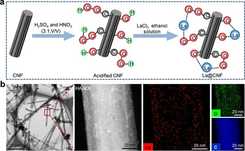
Anhydrous lanthanum chloride (LaCl3, 99.99%, metals basis, Shanghai Aladdin Biochemical Technology Co., Ltd, China) was prepared as the LaCl3 alcohol solution with 0.2 wt.%. Subsequently, the acidified CNF was put into 200 mL of the LaCl3 alcohol solution. After ultrasonic treatment (100 W, 40 kHz) for 3 h, the solution was allowed to stand for 10 h and then washed several times with anhydrous ethanol. Finally, it was dried in an oven at 60°C for 24 h to obtain La@CNF, as schematically exhibited in (a).
Figure 1. (a) Schematic diagram of La grew on CNF in situ; (b) Surface topography obtained by TEM and element mapping images.
The homemade La@CNF was investigated using transmission electron microscopy (TEM, Tecnai G2 F30, USA) equipped with a high-angle annular dark-field detector (HAADF). Before characterisation, the La@CNF in absolute ethanol was dispersed by ultrasound for 15 min. Afterward, the suspension was dropped onto a copper grid and dried at room temperature. The surface chemical state was evaluated by an X-ray photoelectron spectroscopy (XPS, ESCALAB 250Xi, UK) with Al Kα ray (1486.6 eV) at 12.5 kV and 16 mA. The peaks of the measured elements were calibrated by the C1s peak located at 284.6 eV. The chemical structures were analysed by Fourier transform infrared spectra (FT-IR, 605S) in the scanning range from 500 to 4000 cm−1.
2.2. Laser additive manufacturing of Zn-based samples
Spherical Zn powder (15–47 μm) was supplied by Shanghai Nanotechnology Co. Ltd. Zn powder (10.0 g) and La@CNF powder (0.2 g) were homogeneously mixed by mechanical milling at 180 rpm in argon atmosphere for 5 h to obtain La@CNF/Zn mixed powder. Afterward, the as-mixed La@CNF/Zn powder was adopted for the LPBF experiment. The LBFP equipment was composed of a powder-feeding device, a computer control system and an YLR-500-WC fibre laser (IPG, Germany). The laser in this work had a maximum power of 500 W and a beam diameter of ∼70 μm. The optimised processing parameters achieved after several experiments were determined at a laser power of 60 W, a scanning rate of 350 mm/s, a hatch spacing of 60 μm and a thickness of 45 μm. The oxygen concentration was controlled below 0.1 ppm. Additionally, CNF/Zn parts, which contained 0.2 wt.% of CNF, and Zn parts were fabricated by LPBF in the similar conditions.
2.3. Microstructural characterisation
The as-built parts were mechanically ground using SiC papers and then further polished with 10,000 mesh diamond polishing paste. The surface feature was analysed using scanning electron microscopy (SEM, JSM-6701, Japan) equipped with an energy-dispersive spectroscopy (EDS, JSM-5600LV, Japan). The nano-microstructure was investigated utilising high-resolution TEM. The texture was characterised by an electron backscattering diffractometer (EBSD, Oxford Instruments, UK). All samples for EBSD testing were electro-polished in a self-prepared solution containing 37% of orthophosphoric and 63% of ethanol at 5 mV. EBSD data were analysed with Channel 5 software.
2.4. Mechanical tests
Tensile specimens, with a gauge length of 25 mm and a gauge width of 3 mm, were fabricated by LPBF according to the standard of ASTM 8E. The tensile tests were performed by an electronic universal testing machine (CMT-4304, China) equipped with a laser extensometer at a loading rate of 1 mm/min. Subsequently, the slip system and local misorientation of the specimens with a stress–strain of 3% were investigated by EBSD. The fracture morphologies were analysed by SEM. Additionally, hardness tests were measured using a microhardness tester (Beijing TIME High Technology Co. Ltd., China) with a load of 0.98 N and a holding time of 15 s.
2.5. Degradation tests
The degradation behaviour was evaluated using electrochemical experiments and immersion tests. Electrochemical experiments were done by a PARSTAT 2273 electrochemical workstation equipped with a conventional three-electrode cell, in which the test samples were used as a working electrode, the saturated calomel as a reference electrode, and a platinum sheet as a counter electrode. The open-circuit potential (OPC) was monitored for 5000 s to obtain stable potential. Tafel polarisation experiments were done in a potential range within OPC ± 300 mV, and its scanning interval was 0.05 mV/s. Electrochemical impedance spectroscopy (EIS) tests were conducted under a 10 mV of sinusoidal perturbation voltage in the frequency range of 10−2–106 Hz. All measurements were done in a simulated body fluid (SBF) solution at 37°C.
Immersion tests were carried out in SBF with 0.1 cm2/mL at 37°C in accordance with ASTM G31-72. After the immersion for 28 d, Zn ion concentration in SBF was detected using an inductively coupled plasma optical emission spectrometer (ICP-OES, ICAP6300). Additionally, corrosion morphologies were obtained by SEM after removing corrosion products by a CrO3 solution (200 g/L).
2.6. Anti-tumour evaluation
MG-63 osteosarcoma cells (Chinese Academy of Sciences) were used to evaluate anti-tumour properties. Before tests, Dulbecco’s modified Eagle’s medium (DMEM), as the culture medium, was supplemented with 10% fetal bovine serum (FBS) and 1% antibiotics (penicillin and streptomycin). The sterilised parts were immersed in the culture medium for 7 days to take extracts. Subsequently, the cells were incubated in the extracts and the culture medium, respectively. The culture environment was set in a humidified atmosphere with 5% CO2 at 37°C. After incubation for 4 and 7 days, the cells were stained with a combination dye (Calcein-AM/PI) for 30 min, and then obtained by fluorescence microscopy (BX60, Japan). After the same incubation time, the cell counting Kit-8 (CCK-8, Dojindo Laboratories, Japan) solution was introduced and then continuously incubated for 2 h. The absorbance at 450 nm was measured using a paradigm detection platform (Beckman Coulter, CA).
2.7. Cytotoxicity and haemocompatibility evaluation
Rat bone marrow stromal stem cells (BMSCs, Shanghai Lianmai Bioengineering Co. Ltd, China) were purchased to analyse cytotoxicity. First, the sterilised parts (Φ10 × 2 mm) were soaked in the DMEM at 1.25 cm2/mL for 72 h. Extracts were prepared and diluted in different concentrations (100%, 75% and 50%). Subsequently, the cells were incubated in different concentrations of the extracts for 3 and 7 days in 5 vol.% CO2 at 37°C. They were stained with a combination dye (Calcein-AM) for 30 min. Cell morphology was characterised with a fluorescence microscope. Additionally, 50 μL of CCK-8 solution was dropped into a 24-well plate. After 2 h, the optical density at 450 nm was detected by a microplate reader (Beckman Coulter, CA).
Fresh blood from healthy mice (Chinese Academy of Sciences) was used to assess haemocompatibility. First, the parts were immersed in 0.9% of normal saline solutions at 1:3 mL/cm2 to prepare extracts. On the other hand, 0.3 mL of potassium oxalate reagent was added to 9 mL of the blood. Then, 16% of red blood cell suspension was obtained by diluting the blood solution with the normal saline solution. The cell suspension was dripped in the tubes with the extracts, deionised water and 0.9% of the normal saline solution. Finally, supernatants were prepared after the tubes were pre-cultured for 30 min at 37°C in a water bath. The supernatants were measured by an ultraviolet spectrophotometer (UNIC-7200, Shanghai, China) at a wavelength of 545 nm to calculate the haemolysis ratio.
2.8. Cell differentiation tests
The differentiation ability of the stem cell was investigated by detecting alkaline phosphatase (ALP) expression. The cells (1×10⁴ cells/mL) were seeded into a 12-well plate in the DMEM and incubated with sterilised parts for 5 and 10 days. After that, the cell-loaded parts were taken out and placed into a new 24-well plate to wash twice with phosphate-buffered saline (PBS). The cells were fixed using 4% of paraformaldehyde for 30 min and rinsed with PBS. The cells were stained for 5 h by the ALP kit (Wako, Osaka) and visualised with an optical microscope. Besides, the stained solution was extracted by 10% of cetylpyridinium chloride for 10 min. The absorbance at 540 nm was quantitatively analysed on a microplate reader.
Extracellular matrix mineralisation of the stem cells was assessed by Alizarin Red staining. The cells were incubated with sterilised parts for 5 and 10 days. Subsequently, the cells were fixed using 4.0% formaldehyde solution for 10 min after being washed by PBS. After that, they were stained using 40 mM of alizarin red for 30 min with gentle shaking and washed with deionised water. Images of stained cells were obtained with an optical microscope. For quantitative analysis, the deposited calcium of the stained cells was dissolved using 10% of cetylpyridinum chloride. The optical density values were detected at 600 nm.
2.9. Statistical analysis
All experiments were performed at least three times, and then the average calculated. The SPSS 20.0 software was used to analyse the significant difference. P less than 0.05 was recognised the statistical difference.
3. Results and discussions
3.1. Morphologies and structures of powders
Morphologies and EDS mapping of the self-prepared La@CNF powders were investigated to confirm the formation of La on CNF. As shown in (b), the rough surface for La@CNF was observed by HAADF. The corresponding EDS mappings showed that La and oxygen (O) elements were uniformly dispersed on CNF, indicating the formation of a nearly continuous nanolayer. Enriched C elements revealed that a relatively complete fibre structure and a component for CNF were still maintained. To further analyse the microstructure of the nanolayer, TEM images of La@CNF are displayed in (a). The selected area electron diffraction (SAED) pattern displayed diffraction rings for area A1, La2O3, according to the index of JCPDS 5-602 (Tang et al. Citation2004). Furthermore, the interface between CNF and the nanolayer was observed by the high-resolution TEM and inverse Fast Fourier transform (IFFT). Two atom plane spaces were presented on both sides of the interface. The IFFT image also showed clear lattice fringes with the measured inter-planar spacing of 0.35 and 0.29 nm, which were assigned to the crystal planes of (002)C and (101)La2O3, respectively. It was believed that La was in situ grew on an acidified CNF surface since La with high coordination number easily bound with O element on O-containing functional groups of acidified CNF surface by coordination covalent bonds (Dongfeng, Congting, and Xiaoyan Citation2017).
Figure 2. (a) TEM images, including electron diffraction patterns and interface microstructures; (b) FT-IR spectra of La@CNF and original CNF; (c) XPS survey pattern and high-resolution spectra of La3d and O1s for La@CNF.
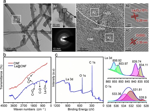
The chemical structures of La@CNF were investigated by FT-IR, as shown in (b). The spectrum of La@CNF presented a strong absorption band at 450 cm−1 compared with CNF, which was attributed to La–O stretching vibration (Jiang, Zhou, and Cheng Citation2019). Besides, the absorption peaks at 1500 and 1170 cm−1 were caused by the resonances of C=O and C–O, respectively, which proved the formation of O-containing groups after acidification. The compositions of La@CNF surface were analysed by XPS, as depicted in (c). The binding energies of C and O elements were detected at 280 and 532 eV, respectively. La element’s binding energy varied from 833 to 855 eV. The quantitative element compositions are exhibited in . For La@CNF, the O1s/C1s ratio was 35.91%, which was significantly enhanced compared with CNF (3.09%). Meanwhile, it also contained 3.27% of La.
Table 1. Element contents detected on La@CNF compared with original CNF provided by Shanghai Kelaman Reagent Co., Ltd.
The high-resolution XPS spectra of La3d and O1s were fitted to further analyse the chemical states. Obviously, La3d spectrum presented peaks at 856.92 and 839.74 eV, which corresponded to La3d3/2 and La3d5/2, respectively. The characteristic peaks shifted towards high binding energy compared with standard peaks, which was mainly affected by the electron coordination bonds of O atoms (Yadav et al. Citation2016; Jiang, Zhou, and Cheng Citation2019). In addition, the satellite peaks appeared at the high-energy side of each characteristic peak. The empty 4f orbital of La was filled with valence electrons of O after the excitation of La3d3/2 and La3d5/2 electrons, thus resulting in the cleft of the characteristic peak (Dongfeng, Congting, and Xiaoyan Citation2017). As for O1s spectrum, the peaks at 533.36 and 531.81 eV corresponded to C–O and C = O, respectively, which shifted to a high binding energy compared with the literature (Kehrer et al. Citation2019; Shutthanandan et al. Citation2019; Wu, Jing, et al. Citation2019). In fact, O atoms coordinated with La could cause its lone-pair electrons to move away, thereby decreasing the outer electron cloud density. Besides, a new peak appeared at 528.9 eV due to the influence of La–O.
3.2. Microstructure of LPBF-processed parts
Cross-section microstructure of Zn and Zn-based composites was observed by SEM in the backscatter model, as displayed in (a). No evident defects, including cracks, pits or pores, appeared in the parts. The densification with ∼99% was achieved for the LPBF-processed parts based on parameters optimisation (Wen et al. Citation2019). For CNF/Zn and La@CNF/Zn, fine and long nanofibres exhibited reticular distribution in the matrix of Zn-based composites compared with Zn. As shown in the EDS line scan spectrum (A1–A2 and B1–B2), the enriched C, La and O elements were detected on nanofibres, which confirmed the CNF and La@CNF.
Figure 3. (a) Cross-section microstructure of Zn- and Zn-based composites by SEM in the backscatter model, and EDS line scan spectra, marked as A1–A2 and B1–B2, respectively; (b) TEM characterisation: (b1) microstructure for Zn; (b2) the interface structure of CNF/Zn; (b3) TEM image and (b4) high-resolution TEM image from the marked box, showing the interface structure of La@CNF/Zn.
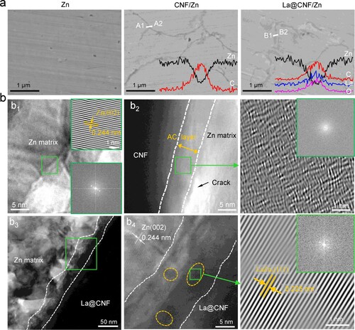
The TEM characterisations for the as-built parts are shown in (b). For Zn, some dislocation accumulation appeared in the matrix, as shown in (b1). The IFFT image also showed a small amount of lattice distortion, which was caused by a high cooling rate during LPBF. A crack appeared at the CNF–Zn interface ((b2)), suggesting poor interfacial bonding. As previously stated, there was a large difference in surface tension between Zn (815 mN/m) and CNF (42 mN/m), which should lead to the poor wettability of CNF in Zn matrix (Hussin, Wahab, and Attan Citation2020; Yang et al. Citation2021). Besides, an amorphous carbon layer was observed at the CNF–Zn interface, likely formed by shear, deformation and compaction originating from the inter-particle interactions at the interface. During LPBF, the instantaneous melting of powders and ultra-high cooling rate also contributed to the formation of the amorphous carbon layer (Yan, Chen, and Li Citation2021). The amorphous carbon layer, as an interface distortion region, usually contained high-density dislocations, which was confirmed by the IFFT and FFT. As a result, internal stress was generated at the CNF–Zn interface, which improved interface bonding.
The interface structure for La@CNF/Zn was used to analyse the influence of La on the interfacial reaction and bonding between CNF and Zn matrix. As shown in (b3), no voids or cracks appeared at the La@CNF–Zn interface, indicating an intimate interface bonding. The local high-resolution TEM at the interface is displayed in (b4). Obviously, some nanophases were at the interface, as marked by ellipses. The region from the marked ellipse was subjected to IFFT, and results showed the lattice fringes with the inter-planar spacing of 0.225 nm corresponded to the (111)LaZn5 plane. Furthermore, the nanophase at the interfacial layer was confirmed as LaZn5 according to JCPDS 39-1056 (Berche et al. Citation2011). The result indicated that La on CNF could bind with the Zn matrix by metallic bonds. It was concluded that La played a bridge role between CNF and Zn, forming a strong interfacial adhesion.
The grain boundary characteristic distribution was analysed, as shown in a. For Zn, high-angle grain boundaries (HAGBs) accounted for 63.5%, delimited coarse grains. After the incorporation of CNF, HAGBs increased to 78.2%. Low-angle grain boundaries (LHGBs) presented in the shape of fine grains, which were possibly ascribed to dislocation accumulation caused by the poor wettability of CNF in the Zn matrix (Akbarpour et al. Citation2020). As for La@CNF/Zn, HAGBs slightly increased to 79.2%, implying that the La on CNF hardly affected the proportion of HAGBs. Additionally, CNF/Zn showed a significant decrease in the average grain size (6.7 μm) compared with Zn (12.3 μm). It was because that the enrichment of CNF in front of a solid–liquid interface hindered the primary grain growth (Chen et al. Citation2019). In contrast, the average grain size for La@CNF/Zn was 6.2 μm, since La on CNF hardly affected the grain growth.
Figure 4. (a) Grain boundary images showing grain boundary characteristic distribution, in which blue and black lines represent LAGBs and HAGBs
, respectively; (b) Inverse pole figures showing grain orientations, in which red, green and blue represent the
,
and
orientations, respectively; (c) Pole maps displaying texture strength in the (0001) crystallographic plane.
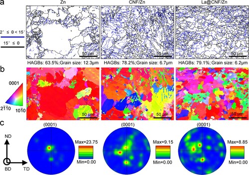
The texture of Zn and Zn-based parts was investigated, as displayed in (b). The grains for Zn mainly showed red, suggesting a preferential grain orientation along direction. After the incorporation of CNF or La@CNF, multiple colours appeared in the Zn matrix, which indicated that the grain growth tendency along
direction was disrupted. In addition, the texture strength wis depicted in (c). For Zn, the pole map in (0001) plane showed a strong fibre texture with a texture intensity of 23.75. The texture intensities of CNF/Zn and La@CNF/Zn were weakened to 9.15 and 8.85, respectively.
3.3. Mechanical properties
Typical tensile curves for LPBF-processed Zn and Zn-based composites are exhibited in (a). The corresponding tensile mechanical parameters were obtained by the stress–strain tensile curves, as shown in (b). For Zn, the YS and ultimate tensile strength (UTS) were 68.7 ± 10.2 and 106.6 ± 11.1 MPa, respectively. The elongation was only 6.5%. After incorporating CNF, the YS and UTS for CNF/Zn were improved to 122.4 ± 11.5 and 180.2 ± 12.1 MPa, respectively. Its elongation slightly increased to 8.1%. Furthermore, La@CNF/Zn showed a remarkably enhanced YS of 158.3 ± 9.1 MPa and UTS of 243.4 ± 10.2 MPa, with a good elongation of 9.3%. The average hardness also increased to 80.3 Hv compared with CNF/Zn (69.4 Hv) and Zn (49.5 Hv), as shown in c.
Figure 5. (a) The stress–strain tensile curves, (b) the corresponding tensile parameters, (c) the hardness, (d) typical fracture surfaces after tensile.
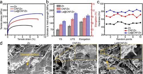
Fracture surfaces after tensile tests are displayed in (c). After introducing CNF, massive small-scale cleavage planes were surrounded by tearing ridges. However, the CNF, pulled out from the Zn matrix, presented a smooth surface without adhering to the residual matrix, as shown in the high-resolution SEM. It represented a weak CNF–Zn interfacial bonding, which formed void and cracks propagation at the interface under loading. Abundant well-distributed dimples distinctively appeared in the fracture of La@CNF/Zn. Besides, a tearing nanofibre was observed in the enlarged view of the selected region. Its surface was covered with Zn. It indicated a firm interface bonding between reinforcements and the Zn matrix, which was conducive to the improvement of load-transfer efficiency.
To understand the strengthening mechanism, the corresponding theoretical analysis was performed based on the microstructures and mechanical properties. Generally, the strengthening mechanism of fibre reinforcement to the matrix mainly depended on solution strengthening, thermal mismatch strengthening, fibre reinforcement and grain refinement (Mandal, Dutta, and Panigrahi Citation2008; Manu et al. Citation2017). In the present work, due to the low solid solubility of C and La in the Zn matrix, the solution strengthening could be ignored. Additionally, the thermal mismatch strengthening was related to thermal expansion coefficients. When the molten composites were rapidly solidified during LPBF, the large difference in the thermal expansion coefficients for CNF (−1 × 10⁻⁶ K−1) and Zn (36 × 10−6 K−1) caused massive lattice distortions near the CNF–Zn interface, increasing dislocation density ((b2)). In this case, the CNF–Zn interface was enhanced. As for La@CNF/Zn, lattice distortion hardly existed in the interface of intermetallic nanoparticles and metal matrix ((b3)) because of the small thermal expansion coefficient difference. Considering this aspect, the thermal mismatch strengthening of La@CNF/Zn could also be neglected.
Fibre reinforcements were governed by the dislocation bypassing and the dislocation pinned by reinforcement, corresponding to the Orowan strengthening and load-transfer strengthening, respectively. Usually, massive dislocations are easily formed and accumulated at the interface between the matrix and reinforcements under an external load (Wang et al. Citation2011). When the diameter of CNF was less than 100 nm, dislocations could bypass them. In this case, back stress was generated to inhibit the propagation of dislocations, thereby realising the Orowan reinforcement. Once the diameter of reinforcements was greater than 100 nm, the dislocations could not bypass them, which caused that the Orowan reinforcement effect would be greatly limited (Zhang et al. Citation2020). Meanwhile, the dislocations were accumulated at the La@CNF–Zn interface, which caused high interfacial shear stress. As shown in (b), the La@CNF–Zn interface had high interface bonding, thus promoting the transfer of stress from the Zn matrix to CNF. In contrast, due to the weak interface bonding between CNF and Zn, dislocations led to the formation and propagation of cracks at the interface, which was unable to realise load-transfer effect fully.
The load-transfer effect strongly depended on the interfacial bonding. For La@CNF/Zn, La was in situ grew on acidified CNF by a chemical synthesis, and closely bound with oxygen of the oxygenated functional group by a coordination covalent bond. On the other hand, it is bound with the Zn matrix by alloying to form a metallic bond. Therefore, it was helpful to enhance the interfacial bonding between CNF and Zn, thereby improving interfacial strength. In this condition, the inherent characteristics of La@CNF could be fully used, which effectively enhanced the load-transfer effect. The result is proved in (c). Compared with La@CNF–Zn, the interface strength of CNF–Zn was improved mainly through Van der Waals force and the amorphous carbon region ((b2)), which easily led to the debonding of CNF from the matrix during deformation. Additionally, fibre reinforcements with the high aspect ratio could also form a network structure in the Zn matrix ((a)). The structure could quickly disperse stress to avoid the crack generation and propagation caused by stress concentration, which improved the fracture toughness of the matrix.
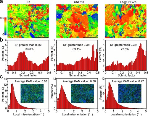
Grain refinement, namely boundary strengthening, is a common strengthening mechanism (Estrin and Vinogradov Citation2013). The grain boundary for Zn was mainly composed of HAGB ((a)). After introducing CNF or La@CNF, the Zn grains were remarkably refined, with the increase of HAGB. HAGB could effectively deflect and even prevent the propagation of microcracks (Li et al. Citation2019). A weakened matrix texture could avoid premature dislocation accumulation, thereby improving matrix ductility. Generally, dislocation accumulation was directly affected by slip system activation (Parkin and Birosca Citation2021). As displayed in (a,b), after the introduction of CNF, the Schmidt factor greater than 0.35 accounted for 63.1%, which indicated that basal slip was easily activated for CNF/Zn compared with Zn (33.8%). For La@CNF/Zn, the introduction of La@CNF increased the proportion of the Schmidt factor to 72.5%. It was attributed to that La with a unique valence electron structure could produce relatively high charge density by charge transfer, which reduced stacking fault energy, thereby promoting basal slip activation (Githens et al. Citation2020). As shown in (c), relatively few green regions appeared in the grain of La@CNF/Zn compared with Zn and CNF/Zn, which reflected a large dislocation accommodation capacity, thus improving the matrix toughness.
Figure 6. (a) Schmid factor maps and (b) corresponding distribution for tensile samples with a stress–strain of 3%; different colours represented various Schmid factors (SF); (c) Kernel average misorientation (KAM) maps and distribution.
3.4. Degradation behaviour
The corrosion behaviour for Zn, CNF/Zn and La@CNF/Zn was evaluated by polarisation curves, as displayed in (a). Corrosion potential (Ecorr) and corrosion current density (Icorr) were obtained by Tafel extrapolation method, as showed in (b). After introducing CNF, the Ecorr changed from −1.01 to −1.32 V. The Icorr increased to 11.83 μA/cm2 compared with Zn (6.17 μA/cm2), which indicated that CNF could accelerate the degradation of the Zn matrix. It was attributed to galvanic corrosion caused by a large electrode potential difference between CNF (0.255 V) and Zn (−0.762 V). However, La@CNF/Zn exhibited a relatively low Icorr (9.11 μA/cm2) compared with CNF/Zn, revealing a high corrosion resistance. In addition, the corrosion rates determined from Ecorr and Icorr for Zn, CNF/Zn and La@CNF/Zn were 0.062 ± 0.006, 0.154 ± 0.009 and 0.062 ± 0.005 mm/year, respectively, as shown in (c).
Figure 7. (a) Polarisation curves, (b) corrosion parameters and (c) corrosion rates determined from (b) for Zn and Zn-based compositions; (d) Nyquist plots inserted into equivalent electrical circuits, and (e) Bode plots; (f) Zn2+ concentration after immersion in SBF and (g) surface character after the removal of corrosion products.
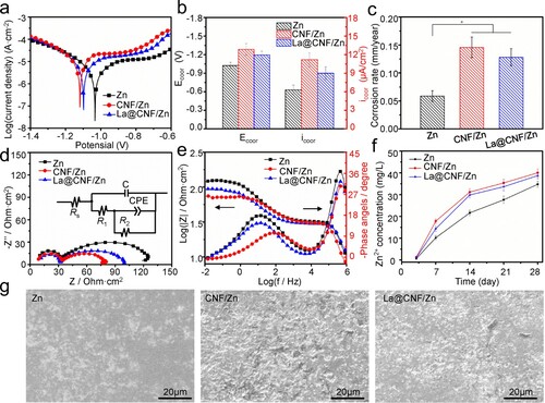
The impedance spectra were analysed for Zn and Zn-based composites. After the introduction of CNF, the capacitive arc diameter decreased to a minimum, as shown in (d). In contrast, the introduction of La@CNF resulted in a relatively large capacitive arc diameter at low frequency, reflecting a high charge transfer resistance. To investigate the corrosion process, Nyquist plots were quantitatively analysed by a suitable equivalent circuit, as shown in (d). Rs, R1 and R2 were the solution resistance, oxide film resistance and charge transfer resistance, respectively. C and CPE were the capacitance of corrosion product and the constant phase element of the interface between the solution and the Zn matrix, respectively. According to the equivalent circuit, the fitted parameters are listed in . After introducing CNF or La@CNF, R1 and R2 were obviously decreased, which were due to the absence of passive film and the decrease of charge transfer resistance, respectively. Besides, the C was also decreased due to the reduction of film thickness. However, the increase of CPE-T was ascribed to the increase of corrosion product at the interface between the solution and the matrix. Furthermore, Bode plots derived from Nyquist plots showed two well-defined time constants at low and high frequencies, as displayed in (e). Maximum high- and low-frequency phase angles decreased after introducing CNF or La@CNF, which further revealed a reduced charge transfer resistance.
Table 2. The fitted parameters obtained by using an equivalent circuit for Zn, CNF/Zn and La@CNF/Zn.
The released Zn2+ concentration was recorded after immersion in SBF for 7, 14, 21 and 28 days, as shown in (f). The Zn2+ concentration gradually increased with extended immersion time. At day 28, Zn2+ concentration reached 34.7 mg/L. After introducing CNF or La@CNF, Zn2+ concentration increased to 40.1 and 38.7 mg/L, respectively. In addition, the surface after removing corrosion products is displayed in (g). After the introduction of CNF, massive corrosion pits appeared on the matrix surface, with the emergence of a lamellar texture. However, La@CNF/Zn showed relatively narrow and small corrosion pits on the surface. It was ascribed to that basic Zn chloride product with good compactness was formed on the surface of the Zn matrix during degradation, which easily formed loose products under the influence of carbonate ion to accelerate matrix corrosion (Rosalbino et al. Citation2009). The La with a special valence electron structure could effectively block the transfer of carbonate ions in the corrosion product layer, which could inhibit the reaction of basic Zn chloride to improve the corrosion resistance (Duchoslav et al. Citation2014).
3.5. Anti-tumour performance
The anti-tumour property was evaluated by MG-63 cells. As displayed in (a), red and green represented the dead and live cells, respectively. For Zn and CNF/Zn groups, few dead cells were observed after incubation for 4 or 7 d. However, massive dead cells appeared in the La@CNF/Zn group. The number of living cells also significantly decreased compared with Zn and CNF/Zn groups, which indicated that La element exhibited excellent anti-tumour efficiency. In addition, the survival rate was quantitatively investigated, as displayed in (b). The cell viability detected from CNF/Zn and Zn groups at day 7 was 83.2% and 80.6%, respectively. The cell viability in La@CNF/Zn extract was 52.8%. It indicated that La element considerably inhibited tumour cell growth, which was consistent with the fluorescence staining test.
Figure 8. (a) MG-63 cell morphology, and (b) the corresponding CCK-8 results after culture in Zn, CNF/Zn and La@CNF/Zn extracts for 4 and 7d; (c) Potential anti-tumour mechanisms of La@CNF/Zn.
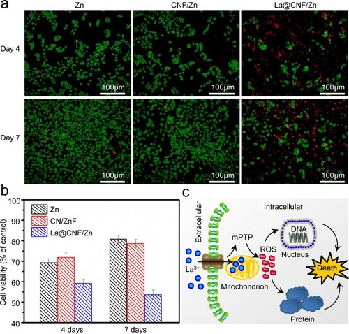
The anti-tumour effect for La@CNF/Zn was mainly determined by the released La ions. It was reported that La ions could be adsorbed on the cellular membrane surface due to their high chemical affinity with O or hydrogen elements, and then modified cellular transport via ionic pumps, thereby leading to high ion permeability (Zhu and Yang Citation2019; Ding et al. Citation2020). As a result, massive La ions entered tumour cells and were then bound to the binding site on mitochondrial permeability transition pore (mPTP) by replacing calcium ions. It was attributed to a large charge radius ratio (2.83) for La compared with calcium (2.02) (Zhong et al. Citation2018; Weiss Citation1974). In this case, the increased ion permeability of mPTP caused ionic balance disorders between cytoplasm and the mitochondrial matrix (Shuai et al. Citation2018). Meanwhile, Perillo et al.(Perillo et al. Citation2014) reported that ions both sides of the cell membrane were redistributed, which caused the decrease of mitochondrial membrane potential, thus blocking the electron transport chain. As a result, the accumulation of reactive oxygen species (ROS) in tumour cells caused oxidative stress, resulting in tumour cell apoptosis (Liu et al. Citation2003). Moreover, Orzołek et al.(Orzołek et al. Citation2013) found that local excess ROS could also cause nucleotide oxidation in DNA, which hindered the normal protein synthesis. The potential anti-tumour mechanisms of released La ions are schematically exhibited in (c).
3.6. Cytocompatibility and haemocompatibility assay
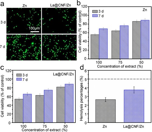
Good biocompatibility is an essential property for implant materials (Yu et al. Citation2021; Gao et al. Citation2021; Qi et al. Citation2022; Meng et al. Citation2020). In this work, the cell behaviour of La@CNF/Zn was studied by BMSCs, with Zn as control. As shown in (a), green represented live cells. On day 7, live cells obviously increased, with the formation of filopodia. The cell growth of the La@CNF/Zn and Zn groups was quantitatively assessed by the CCK-8 assay, as displayed in (b,c). Obviously, the cell viabilities with 100% extracts were less than 75%, which showed some toxicity according to ISO 10993-5. Their cell viabilities gradually increased with the dilution of extraction concentration. For 50% concentration extract, the cell viabilities of La@CNF/Zn and Zn reached 87.4% and 89.1%, respectively. It indicated no obvious toxicity to affect the normal cell growth. The haemolysis percentages of red blood cells are displayed in (d). The haemolysis percentages for La@CNF/Zn and Zn were 3.75% and 2.64%, respectively. According to the ISO 10993-4:2002, their haemolysis results were less than 5%, indicating no haemolysis.
Figure 9. (a) Morphology of BMSCs after culture for 3 and 7 d; (b,c) The CCK-8 results with different concentrations of Zn and La@CNF/Zn extracts; (d) Haemolysis percentages.
3.7. Cell differentiation analysis
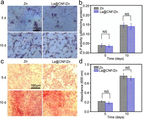
It was valuable to analyse the effect of biomaterials on the differentiation of stem cells into osteoblasts for orthopaedic application (Zhu et al. Citation2017; Zhou et al. Citation2022; Deng et al. Citation2022). As shown in (a), the cell differentiation was first evaluated. Both Zn-based materials could induce significant ALP activity of the cells after culture for 10 days. According to the quantitative analysis ((b)), their ALP activity showed no obvious difference after culture for 5 and 10 days, which was consistent with the results of ALP staining. Besides, the osteogenesis potency of the stem cells was assessed, as displayed in (c). With the extension of culture time, the La@CNF/Zn and Zn groups induced calcification deposition. Quantitative measurements of alizarin red activity are displayed in (d). Extracellular matrix calcium deposition significantly increased after culture for 10 days. Meanwhile, no statistically significant difference was found between Zn and La@CNF/Zn groups.
Figure 10. (a) ALP-staining images of cells, and (b) corresponding ALP activity; (c) alizarin red staining for 5 and 10 days, and (d) quantitative analysis of alizarin red staining; wherein calcium ions could be combined with alizarin red, appearing bright red; NS showed no significant difference.
4. Conclusions
In the present work, rare earth La was in situ grew on CNF by a chemical synthesis method, and then introduced into Zn-based materials to fabricate La@CNF/Zn implants by LPBF. The interface structure, matrix texture, mechanical properties and anti-tumour performance for Zn-based composites were researched. The conclusions were as follows:
Rare earth La served as compatible interface layer between CNF and Zn matrix-enhanced interfacial bonding. On the one hand, La was in situ grew on acidified CNF by a chemical synthesis and achieved a firm coordination covalent bond with O-containing functional groups derived from CNF. On the other hand, it could carry out alloying reaction with Zn matrix to form a metallic bond.
The strengthening mechanisms for La@CNF/Zn were mainly dependent on load-transfer strengthening and grain refinement. The load-transfer effect was remarkably enhanced due to the improvement of interfacial bonding. In addition, the improvement of matrix elongation was ascribed to the activation of basal slip and the improvement of dislocation accommodation.
The La@CNF/Zn displayed excellent anti-tumour efficiency. In its extract, the cell viability was 52.8%, which was attributed to that released La ions inhibited tumour cell growth. Moreover, the introduction of La@CNF had no adverse effect on the normal cell growth and differentiation.
Disclosure statement
No potential conflict of interest was reported by the author(s).
Additional information
Funding
Notes on contributors
Mingli Yang
Mingli Yang is currently a doctoral degree candidate in Metallurgical Engineering at Jiangxi University of Science and Technology. His research interest work is focusing on the research of laser additive manufacturing, biodegradable metals and rare earth functional materials. Up to date, he has (co)authored more than 7 SCI papers.
Yang Shuai
Yang Shuai studied in the college of life science and technology at Huazhong University of science and technology. Her current research focuses on bone repair materials and cancer adjuvant materials. In the past three years, she has published more than 3 SCI papers as (co)author.
Youwen Yang
Youwen Yang is an associate professor at Jiangxi University of Science and Technology. He received his Ph.D. degree from the Central South University in 2019. His current research focuses on laser additive manufacturing and bone repair materials. Up to date, he has (co)authored more than 86 SCI papers.
Da Zeng
Da Zeng is currently working as a manager of basic R & D department in Double Medical Technology Inc. His research interests are in the R & D of orthopedic products such as artificial joints and sports medicine, as well as medical high-value consumables such as general surgery, minimally invasive surgery and orthopedics.
Shuping Peng
Prof. Shuping Peng is professor at Central South University. She received her Ph.D. from Central South University (2006). Her research centers on the development and molecular mechanism of advanced biomaterials and non-coding RNA in osteogenic differentiation of mesenchymal stem cells. Her contributions in the fields are highlighted by multiple publications in journals including Bone Res, Chem Eng J, etc.
Zongjun Tian
Prof. Zongjun Tian is currently a professor at Nanjing University of Aeronautics and Astronautics. He received his Ph.D. from Nanjing University of Aeronautics and Astronautics. His research interests are in the areas of special processing, additive manufacturing and electromechanical control system. He has published more than 60 SCI/EI papers as (co)author.
Cijun Shuai
Prof. Cijun Shuai received his Ph.D. from Central South University in 2006. Currently, he is a professor in Jiangxi University of Science and technology, and Central South University. Prof. Shuai's research interests focus on bioadditive manufacturing. In the past five years, he published 147 SCI papers as first/corresponding author and cited frequency is 7751 times (H index = 47), including 19 ESI highly cited articles.
References
- Akbarpour, M. R., H. Mousa Mirabad, S. Alipour, and H. S. Kim. 2020. “Enhanced Tensile Properties and Electrical Conductivity of Cu-CNT Nanocomposites Processed via the Combination of Flake Powder Metallurgy and High Pressure Torsion Methods.” Materials Science and Engineering: A 773: 138888.
- Andresen, P. A., and D. J. Duquette. 1980. “The Effects of Dissolved Oxygen, Chloride Ion and Applied Potential on the SCC Behavior of Type 304 Stainless Steel in 290 C Water.” Corrosion 36 (8): 409–415.
- Berche, Alexandre, P. Benigni, J. Rogez, and M. C. Record. 2011. “New Experimental Investigation of the Lanthanum Zinc Phase Diagram.” Thermochimica Acta 523 (1–2): 70–78.
- Cha, Jaemin, Joonhui Kim, Seongwoo Ryu, and Soon H Hong. 2019. “Comparison to Mechanical Properties of Epoxy Nanocomposites Reinforced by Functionalized Carbon Nanotubes and Graphene Nanoplatelets.” Composites Part B: Engineering 162: 283–298.
- Chen, Xiaofeng, Jingmei Tao, Yichun Liu, Rui Bao, Fengxian Li, Caiju Li, and Jianhong Yi. 2019. “Interface Interaction and Synergistic Strengthening Behavior in Pure Copper Matrix Composites Reinforced with Functionalized Carbon Nanotube-Graphene Hybrids.” Carbon 146: 736–755.
- Deng, Fang, Ping Wu, Guowen Qian, Yang Shuai, Lemin Zhang, Shuping Peng, Cijun Shuai, and Guoyong Wang. 2022. “Silver-decorated Black Phosphorus: A Synergistic Antibacterial Strategy.” Nanotechnology. https://doi.org/https://doi.org/10.1088/1361-6528/ac5aee.
- Ding, Suwan, Lingfei Lu, Yong Fan, and Fan Zhang. 2020. “Recent Progress in NIR-II Emitting Lanthanide-Based Nanoparticles and Their Biological Applications.” Journal of Rare Earths 38 (5): 451–463.
- Dongfeng, X. U. E., S. U. N. Congting, and C. H. E. N. Xiaoyan. 2017. “Hybridized Valence Electrons of 4f0–145d0–16s2: The Chemical Bonding Nature of Rare Earth Elements.” Journal of Rare Earths 35 (8): 837–843.
- Duchoslav, J., M. Arndt, R. Steinberger, T. Keppert, G. Luckeneder, K. H. Stellnberger, J. Hagler, C. K. Riener, G. Angeli, and D. Stifter. 2014. “Nanoscopic View on the Initial Stages of Corrosion of hot dip Galvanized Zn–Mg–Al Coatings.” Corrosion Science 83: 327–334.
- Estrin, Yuri, and Alexei Vinogradov. 2013. “Extreme Grain Refinement by Severe Plastic Deformation: A Wealth of Challenging Science.” Acta Materialia 61 (3): 782–817.
- Feng, Pei, Jiye Jia, Shuping Peng, Yang Shuai, Hao Pan, Xinna Bai, and Cijun Shuai. 2022. “Transcrystalline Growth of PLLA on Carbon Fiber Grafted with Nano-SiO2 Towards Boosting Interfacial Bonding in Bone Scaffold.” Biomaterials Research 26 (1): 1–15.
- Gao, Chengde, Meng Yao, Shuping Peng, Wei Tan, and Cijun Shuai. 2021. “Pre-oxidation Induced in Situ Interface Strengthening in Biodegradable Zn/Nano-SiC Composites Prepared by Selective Laser Melting.” Journal of Advanced Research. https://doi.org/https://doi.org/10.1016/j.jare.2021.09.014.
- George, R., K. T. Kashyap, R. Rahul, and S. Yamdagni. 2005. “Strengthening in Carbon Nanotube/Aluminium (CNT/Al) Composites.” Scripta Materialia 53 (10): 1159–1163.
- Githens, A., S. Ganesan, Z. Chen, J. Allison, V. Sundararaghavan, and S. Daly. 2020. “Characterizing Microscale Deformation Mechanisms and Macroscopic Tensile Properties of a High Strength Magnesium Rare-Earth Alloy: A Combined Experimental and Crystal Plasticity Approach.” Acta Materialia 186: 77–94.
- Hussin, Fathin Najihah Nor Mohd, Roswanira Abdul Wahab, and Nursyfreena Attan. 2020. “Nanocellulose and Nanoclay as Reinforcement Materials in Polymer Composites: A Review.” Malaysian Journal of Fundamental and Applied Sciences 16 (2): 145–153.
- Jiang, M. R., Hua Zhou, and X. H. Cheng. 2019. “Effect of Rare Earth Surface Modification of Carbon Nanotubes on Enhancement of Interfacial Bonding of Carbon Nanotubes Reinforced Epoxy Matrix Composites.” Journal of Materials Science 54 (14): 10235–10248.
- Katarivas Levy, Galit, Jeremy Goldman, and Eli Aghion. 2017. “The Prospects of Zinc as a Structural Material for Biodegradable Implants – A Review Paper.” Metals 7 (10): 402–420.
- Kehrer, Matthias, Jiri Duchoslav, Andreas Hinterreiter, Munise Cobet, Alen Mehic, Thomas Stehrer, and David Stifter. 2019. “XPS Investigation on the Reactivity of Surface Imine Groups with TFAA.” Plasma Processes and Polymers 16 (4): 1800160. https://doi.org/https://doi.org/10.1002/ppap.201800160.
- Li, Renwei, Qicheng Chen, Mingxi Ji, and Yulong Ding. 2021. “Exploring Failure Mode and Enhancement Mechanism of Doped Rare-Earth Elements Iron-Based/Alumina-Ceramic Interface.” Ceramics International 48 (6): 7827–7835.
- Li, K., L. Wei, B. An, B. Yu, and R. D. K. Misra. 2019. “Aging Phenomenon in low Lattice-Misfit Cobalt-Free Maraging Steel: Microstructural Evolution and Strengthening Behavior.” Materials Science and Engineering: A 739: 445–454.
- Liu, H., L. Yuan, X. Yang, and K. Wang. 2003. “La3+, Gd3+ and Yb3+ Induced Changes in Mitochondrial Structure, Membrane Permeability, Cytochrome c Release and Intracellular ROS Level.” Chemico-Biological Interactions 146 (1): 27–37.
- Liu, Qibing, Genlian Fan, Zhanqiu Tan, Qiang Guo, Dingbang Xiong, Yishi Su, Zhiqiang Li, and Di Zhang. 2021. “Reinforcement with Intragranular Dispersion of Carbon Nanotubes in Aluminum Matrix Composites.” Composites Part B: Engineering 217: 108915.
- Lu, Zhongliang, Jiwei Cao, Zhaoqiang Song, Dichen Li, and Bingheng Lu. 2019. “Research Progress of Ceramic Matrix Composite Parts Based on Additive Manufacturing Technology.” Virtual and Physical Prototyping 14 (4): 333–348.
- Luo, Honglin, Peixun Xiong, Jing Xie, Zhiwei Yang, Yuan Huang, Jimin Hu, Yizao Wan, and Yunhua Xu. 2018. “Uniformly Dispersed Freestanding Carbon Nanofiber/Graphene Electrodes Made by a Scalable Biological Method for High-Performance Flexible Supercapacitors.” Advanced Functional Materials 28 (48): 1803075.
- Mandal, D., B. K. Dutta, and S. C. Panigrahi. 2008. “Effect of Copper and Nickel Coating on Short Steel Fiber Reinforcement on Microstructure and Mechanical Properties of Aluminium Matrix Composites.” Materials Science and Engineering: A 492 (1–2): 346–352.
- Manu, K. M. Sree, S. Arun Kumar, T. P. D. Rajan, M. Riyas Mohammed, and B. C. Pai. 2017. “Effect of Alumina Nanoparticle on Strengthening of Al-Si Alloy Through Dendrite Refinement, Interfacial Bonding and Dislocation Bowing.” Journal of Alloys and Compounds 712: 394–405.
- Martin, Aiden A., Nicholas P. Calta, Saad A. Khairallah, Jenny Wang, Phillip J. Depond, Anthony Y. Fong, Vivek Thampy, Gabe M. Guss, Andrew M. Kiss, and Kevin H. Stone. 2019. “Dynamics of Pore Formation During Laser Powder bed Fusion Additive Manufacturing.” Nature Communications 10 (1): 1–10.
- Meng, Zijie, Jiankang He, Jiaxin Li, Yanwen Su, and Dichen Li. 2020. “Melt-based, Solvent-Free Additive Manufacturing of Biodegradable Polymeric Scaffolds with Designer Microstructures for Tailored Mechanical/Biological Properties and Clinical Applications.” Virtual and Physical Prototyping 15 (4): 417–444.
- Orzołek, Aleksandra, Paweł Wysocki, Jerzy Strzeżek, and Władysław Kordan. 2013. “Superoxide Dismutase (SOD) in Boar Spermatozoa: Purification, Biochemical Properties and Changes in Activity During Semen Storage (16 C) in Different Extenders.” Reproductive Biology 13 (1): 34–40.
- Parkin, James, and Soran Birosca. 2021. “Crystallographic Orientation Influence on Slip System Activation and Deformation Mechanisms in Waspaloy During in-Situ Mechanical Loading.” Journal of Alloys and Compounds 865: 158548.
- Perillo, Bruno, Annalisa Di Santi, Gustavo Cernera, Maria Neve Ombra, Gabriella Castoria, and Antimo Migliaccio. 2014. “Nuclear Receptor-Induced Transcription is Driven by Spatially and Timely Restricted Waves of ROS: The Role of Akt, IKKα, and DNA Damage Repair Enzymes.” Nucleus 5 (5): 482–491.
- Qi, Fangwei, Ruobing Liao, Yang Shuai, Hao Pan, Guowen Qian, Shuping Peng, and Cijun Shuai. 2022. “A Conductive Network Enhances Nerve Cell Response.” Additive Manufacturing 52: 102694. https://doi.org/https://doi.org/10.1016/j.addma.2022.102694.
- Qian, S. Y., Z. H. Xu, H. N. Xie, C. S. Shi, N. Q. Zhao, C. N. He, and E. Z. Liu. 2020. “Effect of Rare Metal Element Interfacial Modulation in Graphene/Cu Composite with High Strength, High Ductility and Good Electrical Conductivity.” Applied Surface Science 533: 147489.
- Qin, Yu, Peng Wen, Hui Guo, Dandan Xia, Yufeng Zheng, Lucas Jauer, Reinhart Poprawe, Maximilian Voshage, and Johannes Henrich Schleifenbaum. 2019. “Additive Manufacturing of Biodegradable Metals: Current Research Status and Future Perspectives.” Acta Biomaterialia 98: 3–22.
- Qiu, Caihao, Yishi Su, Jingyu Yang, Xiaoshu Wang, Boyang Chen, Qiubao Ouyang, and Di Zhang. 2021. “Microstructural Characteristics and Mechanical Behavior of SiC (CNT)/Al Multiphase Interfacial Micro-Zones via Molecular Dynamics Simulations.” Composites Part B: Engineering 220: 108996.
- Rosalbino, F., E. Angelini, D. Macciò, A. Saccone, and S. Delfino. 2009. “Application of EIS to Assess the Effect of Rare Earths Small Addition on the Corrosion Behaviour of Zn–5% Al (Galfan) Alloy in Neutral Aerated Sodium Chloride Solution.” Electrochimica Acta 54 (4): 1204–1209.
- Sathyanarayana, S., and N. Munichandraiah. 1981. “A new Magnesium – air Cell for Long-Life Applications.” Journal of Applied Electrochemistry 11 (1): 33–39.
- Shearier, Emily R, Patrick K Bowen, Weilue He, Adam Drelich, Jaroslaw Drelich, Jeremy Goldman, and Feng Zhao. 2016. “In Vitro Cytotoxicity, Adhesion, and Proliferation of Human Vascular Cells Exposed to Zinc.” ACS Biomaterials Science & Engineering 2 (4): 634–642.
- Shuai, Cijun, Long Liu, Youwen Yang, Chengde Gao, Mingchun Zhao, Lu Yi, and Shuping Peng. 2018. “Lanthanum-Containing Magnesium Alloy with Antitumor Function Based on Increased Reactive Oxygen Species.” Applied Sciences 8 (11): 2109.
- Shuai, Cijun, Li Yu, Pei Feng, Shuping Peng, Hao Pan, and Xinna Bai. 2021. “A Stereocomplexation Constructed Between Poly (D-Lactide) Grafted Hydroxyapatite and Poly (L-Lactide): Toward Bioactive Composite Scaffold with Enhanced Interfacial Bonding.” Journal of Materials Chemistry B 10: 214–223.
- Shutthanandan, Vaithiyalingam, Manjula Nandasiri, Jianming Zheng, Mark H Engelhard, Wu Xu, Suntharampillai Thevuthasan, and Vijayakumar Murugesan. 2019. “Applications of XPS in the Characterization of Battery Materials.” Journal of Electron Spectroscopy and Related Phenomena 231: 2–10.
- Sui, Shang, Youxiang Chew, Fei Weng, Chaolin Tan, Zhenglin Du, and Guijun Bi. 2021. “Achieving Grain Refinement and Ultrahigh Yield Strength in Laser Aided Additive Manufacturing of Ti−6Al−4V Alloy by Trace Ni Addition.” Virtual and Physical Prototyping 16 (4): 417–427.
- Tang, Bo, Jiechao Ge, Changju Wu, Linhai Zhuo, Jinye Niu, Zhenzhen Chen, Zhiqiang Shi, and Yubin Dong. 2004. “Sol–Solvothermal Synthesis and Microwave Evolution of La(OH)3 Nanorods to La2O3 Nanorods.” Nanotechnology 15 (9): 1273–1286.
- Tong, Xian, Zimu Shi, Linchao Xu, Jixing Lin, Dechuang Zhang, Kun Wang, Yuncang Li, and Cuie Wen. 2020. “Degradation Behavior, Cytotoxicity, Hemolysis, and Antibacterial Properties of Electro-Deposited Zn–Cu Metal Foams as Potential Biodegradable Bone Implants.” Acta Biomaterialia 102: 481–492.
- Wang, J., R. G. Hoagland, X. Y. Liu, and A. Misra. 2011. “The Influence of Interface Shear Strength on the Glide Dislocation–Interface Interactions.” Acta Materialia 59 (8): 3164–3173.
- Wang, Chunming, Yang Shuai, Da Zeng Youwen Yang, Xiongwei Liang, Shuping Peng, and Cijun Shuai. 2021. “Amorphous Magnesium Alloy with High Corrosion Resistance Fabricated by Laser Powder Bed Fusion.” Journal of Alloys and Compounds 897: 163247. https://doi.org/https://doi.org/10.1016/j.jallcom.2021.163247.
- Weiss, George B. 1974. “Cellular Pharmacology of Lanthanum.” Annual Review of Pharmacology 14 (1): 343–354.
- Wen, Peng, Yu Qin, Yanzhe Chen, Maximilian Voshage, Lucas Jauer, Reinhart Poprawe, and Johannes Henrich Schleifenbaum. 2019. “Laser Additive Manufacturing of Zn Porous Scaffolds: Shielding gas Flow, Surface Quality and Densification.” Journal of Materials Science & Technology 35 (2): 368–376.
- Wu, Tianjing, Mingjun Jing, Ye Tian, Li Yang, Jiugang Hu, Xiaoyu Cao, Guoqiang Zou, Hongshuai Hou, and Xiaobo Ji. 2019. “Surface-Driven Energy Storage Behavior of Dual-Heteroatoms Functionalized Carbon Material.” Advanced Functional Materials 29 (17): 1900941.
- Wu, Jie, Songbai Xue, Jingwen Wang, and Mingfang Wu. 2019. “Coupling Effects of Rare-Earth Pr and Al2O3 Nanoparticles on the Microstructure and Properties of Sn-0.3Ag-0.7Cu Low-Ag Solder.” Journal of Alloys and Compounds 784: 471–487.
- Yadav, A. A., A. C. Lokhande, J. H. Kim, and C. D. Lokhande. 2016. “Supercapacitive Activities of Porous La2O3 Symmetric Flexible Solid-State Device by Hydrothermal Method.” International Journal of Hydrogen Energy 41 (41): 18311–18329. doi:https://doi.org/10.1016/j.ijhydene.2016.08.028.
- Yan, Q., B. Chen, and J. S. Li. 2021. “Super-high-strength Graphene/Titanium Composites Fabricated by Selective Laser Melting.” Carbon 174: 451–462.
- Yang, Youwen, Yun Cheng, Mingli Yang, Guowen Qian, Shuping Peng, Fangwei Qi, and Cijun Shuai. 2021. “Semi-Coherent Interface Strengthens Graphene/Zinc Scaffolds.” Materials Today Nano 17: 100163. https://doi.org/https://doi.org/10.1016/j.mtnano.2021.100163.
- Yang, Hongtao, Bo Jia, Zechuan Zhang, Xinhua Qu, Guannan Li, Wenjiao Lin, Donghui Zhu, Kerong Dai, and Yufeng Zheng. 2020. “Alloying Design of Biodegradable Zinc as Promising Bone Implants for Load-Bearing Applications.” Nature Communications 11 (1): 1–16.
- Yu, Li, Tiantian He, Wendi Xu, Shuping Peng, Pei Feng, and Cijun Shuai. 2021. “Cu Ions and Cetyltrimethylammonium Bromide Loaded Into Montmorillonite: A Synergistic Antibacterial System for Bone Scaffold.” Materials Chemistry Frontiers 6: 103–116.
- Yu, Xuan, Guangtao Lin, Zhihao Zhang, and Jianxin Xie. 2020. “Electronic Structure Characteristics of Fe-6.5 wt% Si Alloy Doped with Rare Earth Elements and its Effect on Mechanical Properties.” Journal of Alloys and Compounds 843: 155916.
- Yue, Chengbin, Miao Li, Yingtao Liu, Yiqun Fang, Yongming Song, Min Xu, and Jian Li. 2021. “Three-dimensional Printing of Cellulose Nanofibers Reinforced PHB/PCL/Fe3O4 Magneto-Responsive Shape Memory Polymer Composites with Excellent Mechanical Properties.” Additive Manufacturing 46: 102146.
- Zan, Jun, Guowen Qian, Fang Deng, Jun Zhang, Zhikui Zeng, Shuping Peng, and Cijun Shuai. 2022. “Dilemma and Breakthrough of Biodegradable Poly-l-Lactic Acid in Bone Tissue Repair.” Journal of Materials Research and Technology 17: 2369–2387.
- Zhang, Xin, Shufeng Li, Bo Pan, Deng Pan, Lei Liu, Xiaodong Hou, Mingqiang Chu, Katsuyoshi Kondoh, and Maiqun Zhao. 2019. “Regulation of Interface Between Carbon Nanotubes-Aluminum and its Strengthening Effect in CNTs Reinforced Aluminum Matrix Nanocomposites.” Carbon 155: 686–696.
- Zhang, Wenwen, Xin You, Dong Fang, Ping Yang, Jianhong Yi, Xiaohua Yu, Rui Bao, Caiju Li, Yichun Liu, and Jingmei Tao. 2020. “Influence of Acid-Treated Time of Carbon Nanotubes on Mechanical Property in Carbon Nanotubes Reinforced Copper Matrix Composites.” Diamond and Related Materials 109: 108069.
- Zhong, Jiasong, Yongzhao Peng, Daqin Chen, Meijiao Liu, Xinyue Li, Yiwen Zhu, and Zhengguo Ji. 2018. “Highly Efficient Rare-Earth-Free Deep red Emitting Phosphor La2Li1−ySb1−xO6: xMn4+, yMg2+: Application in High-Power Warm w-LEDs.” Journal of Materials Chemistry C 6 (48): 13305–13315.
- Zhou, Zeyang, and T. J. O'keefe. 1997. “Modification of Anomalous Deposition of Zn-Ni Alloy by Using Tin Additions.” Surface and Coatings Technology 96 (2–3): 191–197.
- Zhou, Yan, Jingwen Wang, Youwen Yang, Mingli Yang, Haizhong Zheng, Deqiao Xie, Dongsheng Wang, and Lida Shen. 2022. “Laser Additive Manufacturing of Zinc Targeting for Biomedical Application.” International Journal of Bioprinting 8 (1): 1–31.
- Zhu, Donghui, Irsalan Cockerill, Yingchao Su, Zhaoxiang Zhang, Jiayin Fu, Kee-Won Lee, Jun Ma, Chuka Okpokwasili, Liping Tang, and Yufeng Zheng. 2019. “Mechanical Strength, Biodegradation, and in Vitro and in Vivo Biocompatibility of Zn Biomaterials.” ACS Applied Materials & Interfaces 11 (7): 6809–6819.
- Zhu, Donghui, Yingchao Su, Marcus L Young, Jun Ma, Yufeng Zheng, and Liping Tang. 2017. “Biological Responses and Mechanisms of Human Bone Marrow Mesenchymal Stem Cells to Zn and Mg Biomaterials.” ACS Applied Materials & Interfaces 9 (33): 27453–27461.
- Zhu, Xuefeng, and Weishen Yang. 2019. “Microstructural and Interfacial Designs of Oxygen-Permeable Membranes for Oxygen Separation and Reaction–Separation Coupling.” Advanced Materials 31 (50): 1902547.