
ABSTRACT
Mechanical anisotropy greatly influences the applications of materials printed by additive manufacturing techniques such as Multi Jet Fusion (MJF) and selective laser sintering. However, the mechanical anisotropy of MJF-printed fibre–reinforced polymer composites has not been well understood. In this work, the effect of the fibre length on the mechanical performance of MJF-printed glass fibre–reinforced polyamide 12 (GF/PA12) composites is systematically investigated. Both experimental and simulation results confirm that longer fibres are in favour of fibre alignment in the powder spreading direction. The composite parts with longer fibres exhibit higher porosity. When GFs with an average length of 226 μm are added, the ultimate tensile strength and tensile modulus of the composites measured in the powder bed spreading direction are remarkably improved by 51% and 326%, respectively, as compared with those of neat PA12 specimens. This work provides guidance for the printing of other high-strength fibre–reinforced polymer composites.
1. Introduction
Over the past decades, additive manufacturing (also known as three-dimensional (3D) printing) techniques, such as fused deposition modelling (FDM) (Liao et al. Citation2018; Vaezi and Yang Citation2015), stereolithography (Han et al. Citation2018), selected laser melting (Yap et al. Citation2015), selective laser sintering (SLS) (Yuan et al. Citation2018), direct ink writing (DIW) (Zhang et al. Citation2020), digital light process (Zhao et al. Citation2018), and direct laser writing (Liu et al. Citation2021), have experienced explosive development because they can conveniently produce 3D complex objects for wide applications in biomedical engineering, aerospace, automotive, electronics, and robotics (Han et al. Citation2020; Yuan et al. Citation2019; Parandoush and Lin Citation2017; Yan et al. Citation2020). Among these techniques, FDM and SLS allow line-by-line and layer-by-layer fabrication of 3D products using materials from thermoplastic poly-ether-ether-ketone (PEEK) (Yang et al. Citation2017), polyphenylene sulfide (Fitzharris et al. Citation2018), polypropylene (Spoerk et al. Citation2018), polyamide (PA) (Craft et al. Citation2018), acrylonitrile butadiene styrene (ABS) (Zou et al. Citation2016), poly(lactic) acid (Kotsilkova et al. Citation2019), and poly (butylene terephthalate) (PBT) (Arai et al. Citation2018).
However, because of the heterogeneous interlayer bonding, high mechanical anisotropy is commonly observed in these products, which greatly influences their load-bearing applications. Particularly, the ultimate tensile strength (UTS) of SLS-printed polyamide 12 (PA12) in the Z-build orientation (the direction perpendicular to the build plane) is about 20% lower than that in the powder spreading direction (Sillani et al. Citation2019; Rosso et al. Citation2020; Cai et al. Citation2021). The UTS of FDM-printed ABS and PA12 in the transverse direction (the direction perpendicular to the extrusion direction) is about 10% lower than that in the fibre extrusion direction (Li et al. Citation2017; Zou et al. Citation2016). Moreover, both the SLS-printed PA12 in the Z-build orientation and FDM-printed specimens in the extrusion direction can achieve the lowest tensile modulus and elongation at break.
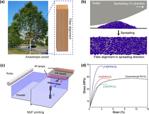
Inspired by anisotropic natural objects such as wood (a), nacre, and lobster claw, researchers have developed various fibre-oriented polymer composites with high mechanical performance (Li et al. Citation2018; Wang et al. Citation2021; Yu et al. Citation2020; Wan et al. Citation2021; Wegst et al. Citation2015; Huang et al. Citation2019; Yang et al. Citation2017). The addition of fibres further intensifies the mechanical anisotropy (Badini et al. Citation2020; Bernasconi, Cosmib, and Dreossi Citation2008; Piggoit Citation1994; Fu and Lauke Citation1996; Halpin Citation1969; Tandon and Weng Citation1984; Hao et al. Citation2020; Hmeidat et al. Citation2020; Tang et al. Citation2021; Dickson et al. Citation2017). Namely, high fibre alignment usually leads to increased material strength and modulus in the alignment direction but decreased material strength and modulus in other directions. Discontinuous fibres such as short CFs and glass fibres (GFs) are commonly used for additive manufacturing because of their processing compatibility (Yan et al. Citation2011; Goodridge et al. Citation2011; Mortazavian and Fatemi Citation2015b; Cai et al. Citation2020). For manufacturing techniques such as FDM, DIW, and injection molding, a higher degree of alignment of discontinuous fibres is realised in the extrusion direction by shear forces (Tekinalp et al. Citation2014; Spoerk et al. Citation2018; Zhao et al. Citation2019; Gantenbein et al. Citation2018; Jiang and Smith Citation2017; Mortazavian and Fatemi Citation2015a; Heller, Smith, and Jack Citation2016). In typical FDM-printed CF (0.2–0.4 mm)-reinforced ABS composites, 91.5% fibre orientation could be achieved (Tekinalp et al. Citation2014). Accordingly, the UTS and tensile modulus could be increased by ∼115% and ∼700%, respectively. The high fibre alignment in FDM-printed specimens can remarkably intensify the mechanical anisotropy. In previously reported FDM-printed CF/polyamide 6 (PA6) composites with 77.0 μm CFs, the UTS (∼39.3 MPa) and tensile modulus (∼3.37 GPa) in the traverse direction were only around 40% and 34% of those in the fibre extrusion direction, respectively (Badini et al. Citation2020).
Figure 1. MJF printing of GF/PA12 composites with bioinspired mechanical anisotropy.
Powder-bed-fusion (PBF) techniques are more versatile than other additive manufacturing techniques because no support structures are required. In a typical PBF technique—SLS, fibres are aligned by a blade or roller in the powder spreading direction (Arai et al. Citation2018; Jansson and Pejryd Citation2016; Arai et al. Citation2019; Chen et al. Citation2021). Although the degree of fibre alignment is not as high as that in FDM and DIW, the corresponding mechanical performance can still be obviously improved. In a previous study, the UTS and tensile modulus of the SLS-printed CF (100–200 μm)/PA12 specimen in the powder spreading direction were increased by ∼39% and ∼280%, respectively, as compared with those of neat PA12 specimens (Jansson and Pejryd Citation2016). The fibre alignment in SLS-printed specimens also intensifies the mechanical anisotropy. For previously reported SLS-printed CF/PA12 composites with 81.8 μm CFs, the UTS and tensile modulus in the bed moving direction were only around 56% and 42% of those in the powder moving direction, respectively (Badini et al. Citation2020).
As a newly developed PBF technique in 2014, Multi Jet Fusion (MJF) offers a higher production rate than SLS (Xu et al. Citation2019) as this technique employs an infrared energy source to fuse the inked powder over a two-dimensional (2D) area (O’Connor, Dickson, and Dowling Citation2018). During the printing process, fusing agent is first jetted from the ink heads to form 2D dark patterns on the preheated powder. Then, infrared lamps pass and retreat over the print bed to fuse the dark powder. Later, the print bed moves down by one layer thickness, and the supply bed moves up by a height in proportion to the layer thickness (defined by the supply ratio). A new layer of powder is then deposited by the roller for the next round of ink jetting. Compared with FDM and SLS, MJF can fabricate PA12 products with lower mechanical anisotropy. Specifically, the corresponding tensile strength and modulus in the Z-build orientation are slightly higher than those in the X- and Y-build orientations, although the elongation at break of the specimens is still low (Cai et al. Citation2021; Chen et al. Citation2021). The increased tensile strength and modulus in the Z-build orientation (about 25% and 35% higher than those of SLS-printed PA12, respectively) are likely due to the better sintering quality between two layers and the reinforcement of carbon black from the fusing agent (Cai et al. Citation2021). Nevertheless, the overall mechanical performance, especially the modulus of MJF-printed PA12 still does not meet the technical requirements for many products.
GFs are excellent fillers for MJF printing because of their white colour and low cost. In our previous works, we have shown that short fibres such as GFs (Liu et al. Citation2021) and aramid fibres (AFs) (Chen et al. Citation2022) could serve as reinforcement fillers for MJF printing. However, the MJF-printed GF/PA12 specimens still suffered from low mechanical performance, and we failed to tune their mechanical anisotropy. Previously reported theoretical and experimental results indicated that the fibre length can remarkably influence the mechanical performance of fibre–reinforced polymers (Arai et al. Citation2018; Hassan et al. Citation2004; Lanzl, Wudy, and Drummer Citation2020; Fu and Lauke Citation1996). Therefore, to fabricate MJF-printed GF/PA12 specimens with desired mechanical performance, it is of both industrial and scientific value to investigate how the fibre length of GFs can influence the mechanical anisotropy of the specimens.
In this work, GFs with different average fibre lengths (124, 226, and 271 μm) have been added into PA12 powder for MJF printing, and the mechanical performances of the specimens in the lamp moving direction, the roller moving direction, and the bed moving direction have been assessed. To find the effects of fibre length on the mechanical anisotropy of the specimens, the powder flowability, fibre alignment, and specimen porosity have been investigated by both experiment and simulation. This work can help to understand and tune the mechanical anisotropy of fibre–reinforced polymer composites.
2. Materials and methods
2.1. Materials
PA12 powder with a median size of 52.6 μm was obtained from HP Inc. (USA). Short silanised GFs with an average fibre diameter of 16 μm were purchased from FIBERTEC CO., Ltd (USA). According to the optical images (the lengths of at least 2000 fibres were measured), the average fibre lengths were 124 μm (product number: 9132), 226 μm (product number: 6616), and 271 μm (product number: 6608), respectively. The fibre length distributions were also calculated. These GFs were denoted as Fibre-124, Fibre-226, and Fibre-271, respectively. The corresponding GF/PA12 powders were denoted as Powder-124, Powder-226, and Powder-271, respectively. The corresponding GF/PA12 specimens were denoted as Specimen-124, Specimen-226, and Specimen-271, respectively. Before MJF printing, 20 wt% GFs were mixed with PA12 powder in an Inversina mixer (2L, Bioengineering AG, Switzerland). The mixing duration was 4 h, and the rotation speed was 60 rpm.
2.2. Experimental design
The HP MJF testbed was obtained from HP Inc. (USA) for MJF printing. This testbed has smaller print and supply beds than commercial MJF printers. b and c illustrates the spreading behaviour of the GF/PA12 powder and schematic of the MJF printer, respectively. During the powder spreading process, a higher degree of fibre alignment is achieved in the roller moving direction than that in the other directions. The volume of both the print bed and supply bed was 190 mm × 65 mm × 180 mm. The supply ratio was adjusted between 2.0 and 2.5, and the roller spreading speed was 200 mm/s. To obtain specimens with desired sizes, the layer thickness was adjusted between 80 and 110 μm, and the lamp speed was adjusted between 14 and 20 inch/s. The preheat temperatures of the print bed and the top surface were set at 150 and 149 °C, respectively. The irradiance of the infrared lamps was 46.66 kW/m2. The heated length of the infrared lamps was 80 mm. The ink density of fusing agent was set at 80%.
The specimens were printed according to the ASTM D638 Type V standard. The thickness and width of the specimens in the gauge part were set at 3.20 and 3.18 mm, respectively. To investigate the anisotropic properties, specimens in the lamp moving direction (X-orientation), the roller moving direction (Y-orientation), and the bed moving direction (Z-orientation) were printed (c). Before and after the printing processes, 10 blank layers were deposited. After a 40 min cooling process, the specimens were collected and bead-blasted, where the glass beads had an average diameter of 83 μm. Later, an optimised annealing process, which can increase the crystallinity of PA12 (Liu et al. Citation2021), was conducted on the specimens to enhance their mechanical performance (Figure S1 and Table S1). The annealing, including a heating process at 5 °C/min, a holding duration of 5 h at 173 °C, and a natural cooling process, was completed in a tube furnace (Nabertherm, Germany) in air. To ensure even heating, the specimens were placed into a crucible, where they were buried in glass beads with an average diameter of 83 μm. The actual annealing temperature was monitored by using a thermometer (K-Type 1319A, RS Pro, Singapore).
2.3. Characterisation
The powder flowability and powder density were measured by a Revolution powder analyzer (Basel, Switzerland). The total avalanche angle (the angle prior to the start of the powder avalanche occurrence) was measured 250 times, and the rotation rate of the drum was set at 0.6 r/min. The optical microscope images were obtained by an Olympus MVX10 microscope (OLYMPUS GmbH, Japan) to determine the fibre orientation (at least 2000 fibres for each specimen). According to previous works (Arai et al. Citation2019; Jansson and Pejryd Citation2016), the fibre orientation was defined as the offset angle between the fibre and the roller moving direction, which was characterised by the software ImageJ. The morphology of the powder and the fracture surface of the printed specimens were characterised by using a scanning electron microscope (SEM) (JSM-5600 LV, JEOL, Japan). Before the SEM analysis, the specimens were coated with a thin gold film to increase the conductivity. The mechanical properties of the printed specimens were characterised using a Shimadzu AGX 10kN universal tester at a strain rate of 1 mm/min. Five specimens were measured for each parameter set. Representative strain curves of MJF-printed specimens in d illustrate the mechanical anisotropy and fibre reinforcement in the roller moving direction. Differential scanning calorimetry (DSC) was conducted by using DSC-Q200 (TA Instruments, UK) with a nitrogen flow rate of 40 mL/min. The heating and cooling cycle was completed from 25 °C to 250 °C at a rate of 10 °C/min. Thermogravimetric analyses (TGA) were conducted using TGA-Q500 (TA Instruments, UK) with a nitrogen flow rate of 40 mL/min and an air flow rate of 20 mL/min. The heating process was completed from 25 °C to 600 °C at a heating rate of 10 °C/min. The weight of the specimen for DSC and TGA was 10 ± 1 mg. The porosity (%), defined as the ratio of the total volume of the pores over the total volume of the specimens, was characterised by high-capacity 3D X-ray computed tomography (Skyscan 1173 Micro CT, Bruker, USA). The accelerating voltage and current were set at 80 kV and 50 mA, respectively. The exposure time was set at 1200 ms, and the spatial resolution of the scan was set at 7.8 μm. The distance between two consecutive layers was set at 10 μm. The porosity was calculated by scanning the specimens with a volume of 2.5 mm × 2.5 mm × 4.0 mm.
3. Results and discussion
3.1. Characterisation results of the GFs and GF/PA12 powder
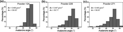
Before MJF printing, the fibre length, powder density, and powder flowability were measured. a–c shows that Fibre-124, Fibre-226, and Fibre-271 had similar diameters of around 16 μm, and the length distribution right-shifted as the length increased (d–f). a–c lists the median avalanche angle Am, avalanche angle distribution, and bulk density Db of the GF/PA12 powder. With the increase in the fibre length, the bulk density decreased from 0.466 g/cm3 (Powder-124) to 0.445 g/cm3 (Powder-271). As indicated by the broader distribution of avalanche angles, the powder flowability became poorer with the increase in fibre length, although all the median avalanche angles of the powders were around 56.5°. The poor powder flowability could also lead to unsuccessful printing. For example, when the layer thickness was 80 μm, Specimen-271 in the X-orientation was displaced by the roller.
Figure 2. SEM images (a–c) and length distributions (d–f) of Fibre-124, Fibre-226, and Fibre-271.
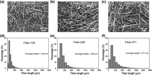
Figure 3. Avalanche angle distributions, median avalanche angles (Am), and bulk densities (Db) of Powder-124 (a), Powder-226 (b), and Powder-271 (c).
3.2. Characterisation results of the MJF-printed GF/PA12 specimens
3.2.1. Thickness of the specimens
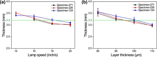
To obtain the specimens with desired sizes, both the lamp speed and layer thickness were optimised. In the main text, we mainly discuss the thickness of the specimens (see Figure S2, Tables S2, and Table S3 for details about the width). As shown in , Table S4, and Table S5, the thickness of all specimens decreased with the increase in the lamp speed and layer thickness. The thickness of Specimen-124 was slightly higher than those of Specimen-226 and Specimen-271 printed at the same lamp speed and layer thickness. This difference is probably due to the higher bulk density of Powder-124. When the lamp speed was 16 inch/s, and the layer thickness was 90 μm, the thicknesses of all the specimens were slightly higher than the design thickness (3.2 mm). In contrast, the thicknesses of both Specimen-226 and Specimen-271 were lower than 3.2 mm with an increase in the lamp speed and layer thickness.
Figure 4. Thicknesses of different specimens prepared at layer thickness = 90 μm (a) and lamp speed = 16 inch/s (b).
3.2.2. Porosity
High porosity usually means a large number of void defects and leads to a weak mechanical performance of the MJF-printed specimens (Zhu and Majewski Citation2020). In this section, we investigated the effects of the lamp speed and layer thickness on the specimen porosity via Micro CT. As shown in , Table S6, and Table S7, the porosity of the specimens followed the sequence: Specimen-271 > Specimen-226 > Specimen-124. This order can be explained by the different powder flowabilities, which followed the sequence: Powder-271 < Powder-226 < Powder-124. Typically, when the lamp speed was 16 inch/s, and the layer thickness was 90 μm, the porosities of Specimen-271, Specimen-226, and Specimen-124 were 3.51%, 2.53%, and 1.38%, respectively. The porosity of the specimens in this work was higher than that of the previous MJF-printed GB/PA12 specimens (O’ O’Connor and Dowling Citation2020) but lower than those of the SLS-printed CF/PA12 specimens (Jing et al. Citation2017; Jansson and Pejryd Citation2016). Lower porosity could also be the result of improved wetting behaviour during the coalescence of the composite powder, indicating that the use of shorter fibre lengths facilitates the wetting of the fibre reinforcement.
Figure 5. Porosity of different specimens: layer thickness = 90 μm (a); lamp speed = 16 inch/s (b).

When the lamp speed increased from 14 inch/s to 20 inch/s, there was a gradual increase in the porosity, which can be explained by the decreased power input. Specifically for Specimen-271, the one printed at the lamp speed of 14 inch/s exhibited a higher porosity than those printed at higher lamp speeds. This is because of the adhesion of surrounding GF/PA12 powder caused by excessive energy input, leading to the creation of large pores near the surface of Specimen-271 printed at the lamp speed of 14 inch/s (Figure S3). Poor flowability and a low lamp speed could lead to slight deformation of the specimens (Specimen-271: 14 and 16 inch/s; Specimen-226 and Specimen-124: 14 inch/s). The deformation can lead to dimensional inaccuracy and degrade the mechanical performance (Figure S4). The porosity of the MJF-printed GF/PA 12 specimens was also influenced by the layer thickness. In this work, the variation in the measured porosity was small when the layer thickness increased from 80 μm to 110 μm (b, Figure S5, and Table S7).
3.2.3. TGA and DSC analysis
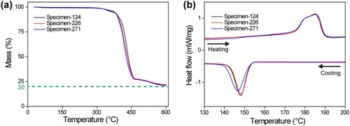
TGA and DSC were used to investigate the fibre content and thermal property of the GF/PA12 specimens. a shows that the fibre contents of Specimen-124, Specimen-226, and Specimen-271 were 21.5, 21.8, and 20.6 wt%, respectively, which were well consistent with that (20 wt%) of the GF/PA12 powder. DSC curves of Specimen-124, Specimen-226, and Specimen-271 were stacked in b. From the heating curves, it is observed that the peak melting temperatures of the three specimens were 185.2, 184.9, and 185.2 °C, respectively, all of which agree well with those of the GB/PA12 composites reported in a previous work (O’ O’Connor and Dowling Citation2020). The broad endotherm peaks around 185 °C suggest that complete sintering of the GF/PA12 powder was achieved.
Figure 6. TGA (a) and DSC (b) curves of Specimen-271, Specimen 226, and Specimen-124.
3.2.4. Fibre alignment
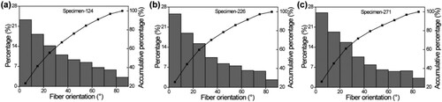
It has been reported that for SLS, fibres could be aligned in the powder spreading direction (Jansson and Pejryd Citation2016; Chen et al. Citation2021; Tan et al. Citation2021). This fibre orientation is mainly related to the shearing flow of the particle pile, which can be adjusted by the layer thickness, spreading speed, and rotating speed of the roller. Such fibre alignment can lead to enhanced mechanical performance of the specimens in the spreading direction over those in other directions. In this work, obvious fibre alignment was also realised in the powder spreading direction by the roller. shows that most glass fibres were laid down in the X-Y plane (build plane) and almost no fibres were oriented parallel to the X-Z plane. To characterise the fibre orientation, the offset angle between the fibre and the spreading direction was measured in the polished X-Y planes of different specimens ( and Table S8). With the increase in the fibre length, there was a slight increase in the fibre alignment in the roller moving direction. Specifically, the percentages of the fibre orientation within 20° were 41.50%, 44.50%, and 45.31% for Specimen-124, Specimen-226, and Specimen-271, respectively.
Figure 7. Optical microscope images of polished X-Y, Y-Z, and X-Z planes in Specimen-124 (a–c), Specimen-226 (d–f), and Specimen-271 (g–i).
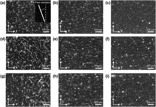
Figure 8. Fibre orientation in the polished X-Y planes of Specimen-124 (a), Specimen-226 (b), and Specimen-271 (c).
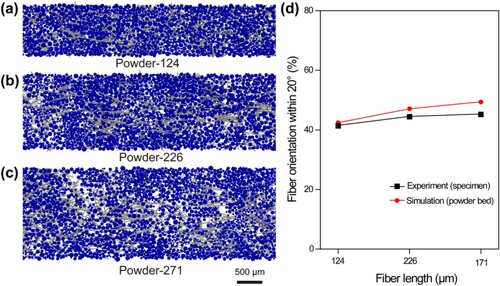
A discrete element model was used to simulate the recoating process of the GF/PA12 composite powder with different fibre lengths. A detailed introduction to the model has been described our previous work (Tan et al. Citation2021). In the simulation, the weight fraction of fibres, the powder layer thickness, and the spreading velocity are 20%, 200 µm, and 0.2 m/s, respectively. A wider powder bed was used for the fibres with a longer length to avoid the influence of lateral boundary conditions. The composite powder beds with different fibre lengths are illustrated in a–c. The percentage of the fibres oriented in the powder spreading direction within 20° (measured from simulated powder beds and printed specimens) versus the fibre length is shown in d. The simulation results confirm that an increase in the fibre length is in favour of the fibre alignment in the powder spreading direction.
Figure 9. Simulated composite powder beds with different types of GFs: (a) Powder-124, (b) Powder-226, and (c) Powder-271 and the percentage of fibres orientated along the powder spreading direction within 20° versus the fibre length.
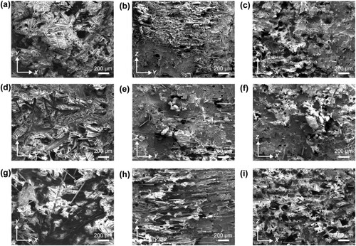
Similar to the optical images of the polished specimens (), the SEM images of the fractured surfaces () also indicate that a relatively high degree of fibre alignment in the Y direction was achieved. As shown in b, e, and h, a large number of glass fibres were laid in the YZ plane and oriented in the Y direction. In contrast, almost no fibres were laid in the XZ plane (c, f, and i).
Figure 10. SEM images of the fractured surfaces of Specimen-124 (a–c), Specimen-226 (d–f), and Specimen-271(g–i) (the lamp speed = 16 inch/s; the layer thickness = 90 μm) in the Z-, X-, and Y- orientation.
3.2.5. Mechanical anisotropy
To investigate the mechanical anisotropy of the MJF-printed GF/PA12 specimens, UTS, tensile modulus, and elongation at break were measured or calculated. The mechanical properties of GF/PA12 specimens in the roller moving direction (Y-orientation) were highly dependent on the fibre length. As shown in , , and Table S9, both the UTS and tensile modulus of the specimens followed the sequence: Specimen-226 > Specimen-271 > Specimen-124. Specifically, the UTS of Specimen-226 was the highest at 67 MPa, which was 8% and 26.4% higher than that of Specimen-271 (62 MPa) and Specimen-124 (53 MPa), respectively. The tensile moduli of the specimens followed a similar trend where the tensile modulus of Specimen-226 was the highest at 5.3 GPa and was 26.2% and 39.5% higher than that of Specimen-271 (4.2 GPa) and Specimen-124 (3.8 GPa), respectively. The mechanical properties of the MJF-printed GF/PA12 specimens in the Y-orientation were also slightly affected by the lamp speed and layer thickness. Specifically, when Specimen-226 was printed at a lamp speed of 16 inch/s or 18 inch/s (layer thickness = 90 μm), the UTS and tensile modulus were 67.31 MPa or 68.69 MPa and 5.84 GPa or 5.07 GPa, respectively. In contrast, the UTS and tensile modulus of PA12 fabricated by a commercial MJF printer were only around 44.5 MPa and 1.37 GPa, respectively (Cai et al. Citation2021). Therefore, when GFs with a moderate length of 226 μm were added, the UTS and tensile modulus in the roller moving direction were increased by about 51% and 326%, respectively. However, the elongation at break of Specimen-226, Specimen-271, and Specimen-124 was around 5%, far lower than that of PA12 fabricated by a commercial MJF printer (∼15.9%).
Figure 11. Mechanical properties of different specimens (a, c, and e: layer thickness = 90 μm; b, d, and f: lamp speed = 16 inch/s) in the Y-orientation.
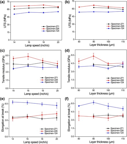
Table 1. Mechanical properties of different specimens (the layer thickness = 90 μm) in the Y-orientation.
The mechanical properties of the GF/PA12 specimens in other orientations were also characterised to investigate the mechanical anisotropy. As shown in and , both the UTS and tensile modulus of these specimens followed the sequence: Y-orientation > X-orientation > Z-orientation. Specifically, the UTS and tensile modulus of Specimen-124/Specimen-226/Specimen-271 in the X-orientation were around 52.58 MPa/48.24 MPa/40.23 MPa and 3.67 GPa/3.05 GPa/2.46 GPa, respectively. The UTS and tensile modulus of Specimen-124/Specimen-226/Specimen-271 in the Z-orientation were around 51.43 MPa/38.54 MPa/29.57 MPa and 2.84 GPa/2.53 GPa/2.16 GPa, respectively. In contrast, the UTS and tensile modulus of PA12 fabricated by a commercial MJF printer in the X/Z-orientation were around 48.7 MPa/49.6 MPa and 1.37 GPa/1.70 GPa, respectively (Cai et al. Citation2021). Therefore, the addition of GFs could increase the modulus of Specimen-124, Specimen-226, and Specimen-271 in all orientations. However, with the exception of Specimen-124, obvious mechanical anisotropy could be observed in Specimen-226 and Specimen-271. The UTS and tensile modulus of Specimen-226 in the Y-orientation were at least 39.5% and 33.4% higher than those in the other two orientations. Similarly, the UTS and tensile modulus of Specimen-271 in the Y-orientation were at least 56.0% and 75.2% higher than those in the other two orientations. Moreover, the elongation at break of all specimens in the Y-orientation was the lowest in all the three orientations.
Figure 12. Stress–strain curves (a–c), UTS (d), tensile modulus (e), and elongation at break (f) of Specimen-124, Specimen-226, and Specimen-271.
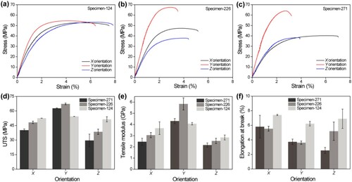
Table 2. Dependence of the mechanical properties of different specimens in the X- and Z-orientations (lamp speed = 16 inch/s; layer thickness = 90 μm).
The different mechanical properties of Specimen-124, Specimen-226, and Specimen-271 were due to the fibre length and the consequential specimen porosity and fibre orientation. First, the mechanical anisotropy of all the specimens can be explained by the different degrees of fibre alignment in the specimens (), which followed the sequence: Y-orientation > X-orientation > Z-orientation. Second, although Specimen-124 had the lowest porosity, it showed lower tensile strength and higher elongation at break in the Y-orientation than Specimen-226 and Specimen-271. The UTS and tensile modulus of Specimen-124 in the X- and Z-orientation were only slightly lower than those in the Y-orientation. The elongation values at break of Specimen-124 in three orientations were higher than those of Specimen-226 and Specimen-271. These results can be explained by the short fibre length and relatively lower degree of fibre alignment in Specimen-124. Specimen-124 exhibited much lower mechanical anisotropy than above mentioned SLS-printed fibe–reinforced polymer composites, which is likely because of the better sintering quality between its two powder layers (Jansson and Pejryd Citation2016; Badini et al. Citation2020). Third, although with a moderate average fibre length, Specimen-226 exhibited better mechanical performance in the three orientations than Specimen-271, which was mainly because of the lower specimen porosity of the former.
Therefore, the mechanical anisotropy of MJF-printed GF/PA12 specimens can be tuned by altering the fibre length. Longer fibres can lead to increased material strength in the fibre alignment direction but decreased material strength in the other directions. Namely, when GFs with a small average length of 124 μm were added, less-anisotropic specimens with enhanced UTS and tensile modulus in all orientations were fabricated. When GFs with a moderate average length of 226 μm were added, the highest UTS and tensile modulus were achieved. When GFs with a large average length of 271 μm were added, the porosity increased and the overall mechanical performance of the GF/PA12 specimens declined as compared with those of the specimens containing GFs with a moderate length of 226 μm.
3.3. Mechanical comparison of 3D-printed PA12 composites by SLS and MJF
To confirm the reinforcement effect of GFs in the MJF-printed GF/PA12 composites in this work, we compared the mechanical performances (in the powder spreading direction) of the PA12, GB/PA12, GF/PA12, and CF/PA12 specimens printed by two typical PBF techniques: SLS and MJF. As shown in , the MJF-printed GF/PA12 specimen (Specimen-226) in the present work exhibited both higher UTS and tensile modulus over all SLS- and MJF-printed PA12, GB/PA12, and GF/PA12 specimens reported in previous studies. Specifically, the UTS (67.31 MPa) and tensile modulus (5.84 GPa) of Specimen-226 were 51.26% and 326.28% higher than those of neat PA12 fabricated by commercial MJF printers, and 54.03% and 115.50% higher than those of the SLS-printed GF/PA12 composites, respectively. Moreover, the mechanical performance of our specimens was also comparable to that of the SLS-printed CF/PA12 composites (UTS = 66−80 MPa; tensile modulus = 5.5−6.3 GPa). Furthermore, the tensile modulus of the MJF-printed GF/PA12 specimens could be increased with the increase in the fibre content. For example, the tensile modulus of MJF-printed Specimen-226 with 25 wt% GFs was 6.21 ± 0.36 GPa. However, the UTS of the specimens decreased slightly to 64.88 ± 3.48 MPa.
Table 3. UTS and tensile modulus (in the powder spreading direction) of PA12-based specimens fabricated by SLS and MJF.
4. Conclusions
We systematically investigated the effect of the fibre length on the mechanical anisotropy of MJF-printed glass fibre–reinforced polyamide 12 (GF/PA12) composites. Both experiment and simulation revealed that longer fibres could lead to higher mechanical anisotropy, as well as lower powder flowability, higher specimen porosity, and better fibre alignment. When GFs with an average length of 226 μm (20 wt%) were added, the UTS and tensile modulus of the composites measured in the powder bed spreading direction were remarkably improved by 51% and 326%, respectively, as compared with those of neat PA12 specimens. To the best of our knowledge, the UTS and tensile modulus of the MJF-printed GF/PA12 composites are comparable to those of SLS-printed CF/PA12 composites and higher than those of previously reported MJF- and SLS-printed PA12, GB/PA12, and GF/PA12 composites. This work is envisioned to provide valuable guidance for researchers to print other high-performance fibre–reinforced polymers.
Acknowledgments
This study is supported under the RIE2020 Industry Alignment Fund Industry Collaboration Projects (IAF-ICP) Funding Initiative as well as cash and in-kind contribution from the industry partner, HP Inc.
Disclosure statement
No potential conflict of interest was reported by the author(s).
Additional information
Funding
Notes on contributors
Xiaojiang Liu
Xiaojiang Liu is a Research Fellow in HP-NTU Digital Manufacturing Corporate Lab, School of Mechanical and Aerospace Engineering, Nanyang Technological University, Singapore.
Wei Shian Tey
Wei Shian Tey is a PhD candidate in HP-NTU Digital Manufacturing Corporate Lab, School of Mechanical and Aerospace Engineering, Nanyang Technological University, Singapore.
Pengfei Tan
Pengfei Tan is a Research Fellow in HP-NTU Digital Manufacturing Corporate Lab, School of Mechanical and Aerospace Engineering, Nanyang Technological University, Singapore.
Kah Kit Leong
Kah Kit Leong is an undergraduate in School of Mechanical and Aerospace Engineering, Nanyang Technological University, Singapore.
Jiayao Chen
Jiayao Chen is a Research Fellow in HP-NTU Digital Manufacturing Corporate Lab, School of Mechanical and Aerospace Engineering, Nanyang Technological University, Singapore.
Yujia Tian
Yujia Tian is a PhD candidate in School of Mechanical and Aerospace Engineering, Nanyang Technological University, Singapore.
Adrian Ong
Adrian Ong is a Senior Engineer in HP-NTU Digital Manufacturing Corporate Lab, School of Mechanical and Aerospace Engineering, Nanyang Technological University, Singapore.
Lihua Zhao
Lihua Zhao is the Global Head of 3D Lab at HP Labs, HP inc., USA, and a principal investigator in HP-NTU Digital Manufacturing Corporate Lab, School of Mechanical and Aerospace Engineering, Nanyang Technological University, Singapore.
Kun Zhou
Kun Zhou is an Associate Professor in School of Mechanical and Aerospace Engineering, Nanyang Technological University, Singapore.
References
- Arai, S., S. Tsunoda, A. Yamaguchi, and T. Ougizawa. 2018. “Effects of Short-Glass-Fiber Content on Material and Part Properties of Poly(Butylene Terephthalate) Processed by Selective Laser Sintering.” Additive Manufacturing 21: 683–693.
- Arai, S., S. Tsunoda, A. Yamaguchi, and T. Ougizawa. 2019. “Effect of Anisotropy in the Build Direction and Laser-Scanning Conditions on Characterization of Short-Glass-Fiber–Reinforced PBT for Laser Sintering.” Optics & Laser Technology 113: 345–356.
- Badini, C., E. Padovano, R. D. Camillis, V. G. Lambertini, and M. Pietroluongo. 2020. “Preferred Orientation of Chopped Fibers in Polymer-Based Composites Processed by Selective Laser Sintering and Fused Deposition Modeling: Effects on Mechanical Properties.” Journal of Applied Polymer Science 137 (38): 49152.
- Bernasconi, A., F. Cosmib, and D. Dreossi. 2008. “Local Anisotropy Analysis of Injection Moulded Fibre Reinforced Polymer Composites.” Composites Science and Technology 68: 2574–2581.
- Cai, C., W. S. Tey, J. Chen, W. Zhu, X. Liu, T. Liu, L. Zhao, and K. Zhou. 2021. “Comparative Study on 3D Printing of Polyamide 12 by Selective Laser Sintering and Multi jet Fusion.” Journal of Materials Processing Technology 288: 116882.
- Cai, H., J. Ye, Y. Wang, M. Saafi, B. Huang, D. Yang, and J. Ye. 2020. “An Effective Microscale Approach for Determining the Anisotropy of Polymer Composites Reinforced with Randomly Distributed Short Fibers.” Composite Structures 240: 112087.
- Cano, A. J., A. Salazar, and J. Rodríguez. 2018. “Effect of Temperature on the Fracture Behavior of Polyamide 12 and Glass-Filled Polyamide 12 Processed by Selective Laser Sintering.” Engineering Fracture Mechanics 203: 66–80.
- Chen, J., P. Tan, X. Liu, W. S. Tey, A. Ong, L. Zhao, and K. Zhou. 2022. “High-strength Light-Weight Aramid Fibre/Polyamide 12 Composites Printed by Multi Jet Fusion.” Virtual and Physical Prototyping 17 (2): 295–307.
- Chen, K., H. W. B. Teo, W. Rao, G. Kang, K. Zhou, J. Zeng, and H. Du. 2021a. “Experimental and Modeling Investigation on the Viscoelastic-Viscoplastic Deformation of Polyamide 12 Printed by Multi Jet Fusion.” International Journal of Plasticity 143: 103029.
- Chen, H., W. Zhu, H. Tang, and W. Yan. 2021b. “Oriented Structure of Short Fiber Reinforced Polymer Composites Processed by Selective Laser Sintering: The Role of Powder-Spreading Process.” International Journal of Machine Tools and Manufacture 163: 103703.
- Craft, G., J. Nussbaum, N. Crane, and J. P. Harmon. 2018. “Impact of Extended Sintering Times on Mechanical Properties in PA-12 Parts Produced by Powderbed Fusion Processes.” Additive Manufacturing 22: 800–806.
- Dickson, A. N., J. N. Barry, K. A. McDonnell, and D. P. Dowling. 2017. “Fabrication of Continuous Carbon, Glass and Kevlar Fibre Reinforced Polymer Composites Using Additive Manufacturing.” Additive Manufacturing 16: 146–152.
- Fitzharris, E. R., I. Watt, D. W. Rosen, and M. L. Shofne. 2018. “Interlayer Bonding Improvement of Material Extrusion Parts with Polyphenylene Sulfide Using the Taguchi Method.” Additive Manufacturing 24: 287–297.
- Fu, S.-Y., and B. Lauke. 1996. “Effects of Fiber Length and Fiber Orientation Distributions on the Tensile Strength of Short-Fiber–Reinforced Polymers.” Composites Science and Technology 56: 1179–1190.
- Gantenbein, S., K. Masania, W. Woigk, J. P. W. Sesseg, T. A. Tervoort, and A. R. Studart. 2018. “Three-dimensional Printing of Hierarchical Liquid-Crystal-Polymer Structures.” Nature 561: 226–230.
- Goodridge, R. D., M. L. Shofner, R. J. M. Hague, M. McClelland, M. R. Schlea, R. B. Johnson, and C. J. Tuck. 2011. “Processing of a Polyamide-12/Carbon Nanofibre Composite by Laser Sintering.” Polymer Testing 30 (1): 94–100.
- Halpin, J. C. 1969. “Stiffness and Expansion Estimates for Oriented Short Fiber Composites.” Journal of Composite Materials 3: 732–734.
- Han, C., Q. Fang, Y. Shi, S. B. Tor, C. K. Chua, and K. Zhou. 2020. “Recent Advances on High-Entropy Alloys for 3D Printing.” Advanced Materials 32 (26): 1903855.
- Han, D., Z. Lu, S. A. Chester, and H. Lee. 2018. “Micro 3D Printing of a Temperature-Responsive Hydrogel Using Projection Micro-Stereolithography.” Scientific Reports 8 (1): 1963.
- Hao, X., H. Zhou, B. Mu, L. Chen, Q. Guo, X. Yi, L. Sun, Q. Wang, and R. Ou. 2020. “Effects of Fiber Geometry and Orientation Distribution on the Anisotropy of Mechanical Properties, Creep Behavior, and Thermal Expansion of Natural Fiber/HDPE Composites.” Composites Part B: Engineering 185: 107778.
- Hassan, A., R. Yahya, A. H. Yahaya, A. R. M. Tahir, and P. R. Hornsby. 2004. “Tensile, Impact and Fiber Length Properties of Injection-Molded Short and Long Glass Fiber–Reinforced Polyamide 6,6 Composites.” Journal of Reinforced Plastics and Composites 23 (9): 969–986.
- Heller, B. P., D. E. Smith, and D. A. Jack. 2016. “Effects of Extrudate Swell and Nozzle Geometry on Fiber Orientation in Fused Filament Fabrication Nozzle Flow.” Additive Manufacturing 12: 252–264.
- Hmeidat, N. S., R. C. Pack, S. J. Talley, R. B. Moore, and B. G. Compton. 2020. “Mechanical Anisotropy in Polymer Composites Produced by Material Extrusion Additive Manufacturing.” Additive Manufacturing 34: 101385.
- Huang, W., D. Restrepo, J. Y. Jung, F. Y. Su, Z. Liu, R. O. Ritchie, J. McKittrick, P. Zavattieri, and D. Kisailus. 2019. “Multiscale Toughening Mechanisms in Biological Materials and Bioinspired Designs.” Advanced Materials 31 (43): 1901561.
- Jansson, A., and L. Pejryd. 2016. “Characterisation of Carbon Fibre-Reinforced Polyamide Manufactured by Selective Laser Sintering.” Additive Manufacturing 9: 7–13.
- Jiang, D., and D. E. Smith. 2017. “Anisotropic Mechanical Properties of Oriented Carbon Fiber Filled Polymer Composites Produced with Fused Filament Fabrication.” Additive Manufacturing 18: 84–94.
- Jing, W., C. Hui, W. Qiong, L. Hongbo, and L. Zhanjun. 2017. “Surface Modification of Carbon Fibers and the Selective Laser Sintering of Modified Carbon Fiber/Nylon 12 Composite Powder.” Materials & Design 116: 253–260.
- Kotsilkova, R., I. Petrova-Doycheva, D. Menseidov, E. Ivanov, A. Paddubskaya, and P. Kuzhir. 2019. “Exploring Thermal Annealing and Graphene-Carbon Nanotube Additives to Enhance Crystallinity, Thermal, Electrical and Tensile Properties of Aged Poly(Lactic) Acid-Based Filament for 3D Printing.” Composites Science and Technology 181: 107712.
- Lanzl, L., K. Wudy, and D. Drummer. 2020. “The Effect of Short Glass Fibers on the Process Behavior of Polyamide 12 During Selective Laser Beam Melting.” Polymer Testing 83: 106313.
- Li, T., J. Song, X. Zhao, Z. Yang, G. Pastel, S. Xu, C. Jia, et al. 2018. “Anisotropic, Lightweight, Strong, and Super Thermally Insulating Nanowood with Naturally Aligned Nanocellulose.” Science Advances 4 (3): eaar3724.
- Li, H., S. Zhang, Z. Yi, J. Li, A. Sun, J. Guo, and G. Xu. 2017. “Bonding Quality and Fracture Analysis of Polyamide 12 Parts Fabricated by Fused Deposition Modeling.” Rapid Prototyping Journal 23 (6): 973–982.
- Liao, G., Z. Li, Y. Cheng, D. Xu, D. Zhu, S. Jiang, J. Guo, X. Chen, G. Xu, and Y. Zhu. 2018. “Properties of Oriented Carbon Fiber/Polyamide 12 Composite Parts Fabricated by Fused Deposition Modeling.” Materials & Design 139: 283–292.
- Liu, X., W. S. Tey, J. Y. C. Choo, J. Chen, P. Tan, C. Cai, A. Ong, L. Zhao, and K. Zhou. 2021. “Enhancing the Mechanical Strength of Multi Jet Fusion–Printed Polyamide 12 and its Glass Fiber–Reinforced Composite via High-Temperature Annealing.” Additive Manufacturing 46: 102205.
- Liu, X., M. Wei, Q. Wang, Y. Tian, J. Han, H. Gu, H. Ding, Q. Chen, K. Zhou, and Z. Gu. 2021. “Capillary-Force-Driven Self-Assembly of 4D-Printed Microstructures.” Advanced Materials 33 (22): 2100332.
- Mortazavian, S., and A. Fatemi. 2015. “Effects of Fiber Orientation and Anisotropy on Tensile Strength and Elastic Modulus of Short Fiber Reinforced Polymer Composites.” Composites Part B: Engineering 72: 116–129.
- Mortazavian, S., and A. Fatemi. 2015. “Fatigue Behavior and Modeling of Short Fiber Reinforced Polymer Composites Including Anisotropy and Temperature Effects.” International Journal of Fatigue 77: 12–27.
- O’Connor, H. J., A. N. Dickson, and D. P. Dowling. 2018. “Evaluation of the Mechanical Performance of Polymer Parts Fabricated Using a Production Scale Multi jet Fusion Printing Process.” Additive Manufacturing 22: 381–387.
- O’Connor, H. J., and D. P. Dowling. 2020. “Comparison Between the Properties of Polyamide 12 and Glass Bead Filled Polyamide 12 Using the Multi jet Fusion Printing Process.” Additive Manufacturing 31: 100961.
- Parandoush, P., and D. Lin. 2017. “A Review on Additive Manufacturing of Polymer-Fiber Composites.” Composite Structures 182: 36–53.
- Piggoit, M. R. 1994. “Short Fibre Polymer Composites: A Fracture-Based Theory of Fibre Reinforcement.” Journal of Composite Materials 28: 588–606.
- Rosso, S., R. Meneghello, L. Biasetto, L. Grigolato, G. Concheri, and G. Savio. 2020. “In-depth Comparison of Polyamide 12 Parts Manufactured by Multi Jet Fusion and Selective Laser Sintering.” Additive Manufacturing 36: 101713.
- Salazar, A., A. Rico, J. Rodríguez, J. Segurado Escudero, R. Seltzer, and F. Martin de la Escalera Cutillas. 2014. “Fatigue Crack Growth of SLS Polyamide 12: Effect of Reinforcement and Temperature.” Composites Part B: Engineering 59: 285–292.
- Sillani, F., R. G. Kleijnen, M. Vetterli, M. Schmid, and K. Wegener. 2019. “Selective Laser Sintering and Multi jet Fusion: Process-Induced Modification of the raw Materials and Analyses of Parts Performance.” Additive Manufacturing 27: 32–41.
- Spoerk, M., C. Savandaiah, F. Arbeiter, G. Traxler, L. Cardon, C. Holzer, and J. Sapkota. 2018. “Anisotropic Properties of Oriented Short Carbon Fibre Filled Polypropylene Parts Fabricated by Extrusion-Based Additive Manufacturing.” Composites Part A: Applied Science and Manufacturing 113: 95–104.
- Tan, P., F. Shen, W. S. Tey, and K. Zhou. 2021. “A Numerical Study on the Packing Quality of Fibre/Polymer Composite Powder for Powder bed Fusion Additive Manufacturing.” Virtual and Physical Prototyping 16 (S1): S1–S18.
- Tandon, G. P., and G. J. Weng. 1984. “The Effect of Aspect Ratio of Inclusions on the Elastic Properties of Unidirectionally Aligned Composites.” Polymer Composites 5: 327–333.
- Tang, H., H. Chen, Q. Sun, Z. Chen, and W. Yan. 2021. “Experimental and Computational Analysis of Structure-Property Relationship in Carbon Fiber Reinforced Polymer Composites Fabricated by Selective Laser Sintering.” Composites Part B: Engineering 204: 108499.
- Tekinalp, H. L., V. Kunc, G. M. Velez-Garcia, C. E. Duty, L. J. Love, A. K. Naskar, C. A. Blue, and S. Ozcan. 2014. “Highly Oriented Carbon Fiber–Polymer Composites via Additive Manufacturing.” Composites Science and Technology 105: 144–150.
- Vaezi, M., and S. Yang. 2015. “Extrusion-based Additive Manufacturing of PEEK for Biomedical Applications.” Virtual and Physical Prototyping 10 (3): 123–135.
- Wan, S., Y. Chen, S. Fang, S. Wang, Z. Xu, L. Jiang, R. H. Baughman, and Q. Cheng. 2021. “High-strength Scalable Graphene Sheets by Freezing Stretch-Induced Alignment.” Nature Materials 20 (5): 624–631.
- Wang, X., J. Fang, W. Zhu, C. Zhong, D. Ye, M. Zhu, X. Lu, Y. Zhao, and F. Ren. 2021. “Bioinspired Highly Anisotropic, Ultrastrong and Stiff, and Osteoconductive Mineralized Wood Hydrogel Composites for Bone Repair.” Advanced Functional Materials 31: 2010068.
- Wegst, U. G., H. Bai, E. Saiz, A. P. Tomsia, and R. O. Ritchie. 2015. “Bioinspired Structural Materials.” Nature Materials 14 (1): 23–36.
- Xu, Z., Y. Wang, D. Wu, K. P. Ananth, and J. Bai. 2019. “The Process and Performance Comparison of Polyamide 12 Manufactured by Multi jet Fusion and Selective Laser Sintering.” Journal of Manufacturing Processes 47: 419–426.
- Yan, C., L. Hao, L. Xu, and Y. Shi. 2011. “Preparation, Characterisation and Processing of Carbon Fibre/Polyamide-12 Composites for Selective Laser Sintering.” Composites Science and Technology 71 (16): 1834–1841.
- Yan, C., G. Ma, A. Chen, Y. Chen, J. Wu, W. Wang, S. Yang, and Y. Shi. 2020. “Additive Manufacturing of Hydroxyapatite and its Composite Materials: A Review.” Journal of Micromechanics and Molecular Physics 05 (3): 2030002.
- Yang, Y., Z. Chen, X. Song, Z. Zhang, J. Zhang, K. K. Shung, Q. Zhou, and Y. Chen. 2017. “Biomimetic Anisotropic Reinforcement Architectures by Electrically Assisted Nanocomposite 3D Printing.” Advanced Materials 29: 1605750.
- Yang, C., X. Tian, D. Li, Y. Cao, F. Zhao, and C. Shi. 2017. “Influence of Thermal Processing Conditions in 3D Printing on the Crystallinity and Mechanical Properties of PEEK Material.” Journal of Materials Processing Technology 248: 1–7.
- Yap, C. Y., C. K. Chua, Z. L. Dong, Z. H. Liu, D. Q. Zhang, L. E. Loh, and S. L. Sing. 2015. “Review of Selective Laser Melting: Materials and Applications.” Applied Physics Reviews 2: 041101.
- Yu, Z.-L., B. Qin, Z.-Y. Ma, Y.-C. Gao, Q.-F. Guan, H.-B. Yang, and S.-H. Yu. 2020. “Emerging Bioinspired Artificial Woods.” Advanced Materials 33 (28): 2001086.
- Yuan, S., F. Shen, C. K. Chua, and K. Zhou. 2019. “Polymeric Composites for Powder-Based Additive Manufacturing: Materials and Applications.” Progress in Polymer Science 91: 141–168.
- Yuan, S., Y. Zheng, C. K. Chua, Q. Yan, and K. Zhou. 2018. “Electrical and Thermal Conductivities of MWCNT/Polymer Composites Fabricated by Selective Laser Sintering.” Composites Part A: Applied Science and Manufacturing 105: 203–213.
- Zhang, M., Y. Wang, M. Jian, C. Wang, X. Liang, J. Niu, and Y. Zhang. 2020. “Spontaneous Alignment of Graphene Oxide in Hydrogel During 3D Printing for Multistimuli-Responsive Actuation.” Advanced Science 7 (6): 1903048.
- Zhao, Z., X. Kuang, C. Yuan, H. J. Qi, and D. Fang. 2018. “Hydrophilic/Hydrophobic Composite Shape-Shifting Structures.” ACS Applied Materials & Interfaces 10 (23): 19932–19939.
- Zhao, C., P. Zhang, R. Shi, Y. Xu, L. Zhang, R. Fang, T. Zhao, S. Qi, L. Jiang, and M. Liu. 2019. “Super-tough and Strong Nanocomposite Fibers by Flow-Induced Alignment of Carbon Nanotubes on Grooved Hydrogel Surfaces.” Science China Materials 62 (9): 1332–1340.
- Zhu, Z., and C. Majewski. 2020. “Understanding Pore Formation and the Effect on Mechanical Properties of High Speed Sintered Polyamide-12 Parts: A Focus on Energy Input.” Materials & Design 194: 108937.
- Zou, R., Y. Xia, S. Liu, P. Hu, W. Hou, Q. Hu, and C. Shan. 2016. “Isotropic and Anisotropic Elasticity and Yielding of 3D Printed Material.” Composites Part B: Engineering 99: 506–513.