
ABSTRACT
Graphene oxide (GO) and molybdenum disulphide (MoS2), have drawn more and more attention as reinforcement in polymer. However, their large specific surface area and strong van der Waals forces result in serious aggregations in polymer matrix, which restrains the reinforcement effect. In this study, MoS2 nanosheets were in situ synthesised vertically and uniformly on the surface of GO nanosheets with the help of a hexadecyl trimethyl ammonium bromide (CTAB) assisted hydrothermal process to facilitate their dispersion in polylactic acid (PLLA) scaffold manufactured via selective laser sintering (SLS). The experimental results revealed that the 1.5 wt% GO/MoS2 nanocomposite exhibited better dispersion state compared with the 1.5 wt% GO and 1.5 wt% MoS2 in PLLA matrix. Therefore, the PLLA scaffold loading 1.5 wt% GO/MoS2 presented 10.2 and 1461 MPa of tensile strength and modulus with enhancement of 61% and 58%, respectively, compared with the pure PLLA scaffold. The reinforcement mechanisms mainly included crack deflection, crack bridging, crack pinning and pulling out of GO/MoS2. What’s more, the GO/MoS2-PLLA scaffold possessed benign cytocompatibility for cell behaviour, suggesting hopeful applications in bone defect repair.
1. Introduction
Two-dimensional (2D) nanomaterials with outstanding properties, including unique flake structures, large surface areas and excellent mechanical strength, have attracted increasing attention in reinforcing polymer with the help of crack branching, crack bridging, pull-out and so on (Vatanpour et al. Citation2021; Dewapriya and Meguid Citation2018; Liu, Hui, and Lau Citation2022). As a typical kind of 2D nanomaterials, graphene oxide (GO), consisting of sp2 bonded carbon atoms layers in hexagonal lattice, possesses desired Young’s modulus of 1 TPa and tensile strength of 130 GPa (Wang, Guan, Fischer, StefanWehner, Li, Wang, and Guoa, Citation2021; Dhinakaran et al. Citation2020; Yang, Shuai et al. Citation2022). Molybdenum disulphide (MoS2), known as a novel graphene-like transition-metal dichalcogenides (TMDs), builds up of covalently bonded S-Mo-S atomic layers via forces, which exhibits outstanding mechanical properties including strong tensile strength of 23 GPa and Young’s modulus of 300 GPa (Rodriguez et al. Citation2021; Gupta, Chauhan, and Kumar Citation2020). GO and MoS2 have been widely used as nanomaterials to enhance the mechanical properties of polymer scaffolds (Arslan et al. Citation2021; Sethulekshmia et al. Citation2021). Mollaqasem et al. (Citation2021) introduced GO into the PCL/PHBV bone scaffold and enhanced the mechanical properties of the scaffold. Qi et al. (Citation2021) added MoS2 to the PVDF scaffold, which improved the mechanical properties of the scaffold. However, in spite of excellent mechanical properties, the most salient problem of GO and MoS2 is that they are prone to generate irreversible agglomerations in polymer matrix because of high specific surface area and strong interaction forces, resulting in reduced reinforcement efficiency (Wu, Yin, Mu, Feng, Lu, and Shi, Citation2021; Gao, Liu, Zhang, Zhang, Li, and Han, Citation2022; Lin et al. Citation2021).
Surface modification has been widely applied in the field of improving dispersion of GO or MoS2, which refers that modifiers can be attached or bonded on the surface of nanomaterials non-covalently or covalently, thereby contributing to arranging a thin layer as a physical barrier to weaken interaction force, and finally hinder their aggregations (Gnanasekar et al. Citation2021; Peng et al. Citation2021; Yan et al. Citation2021). For instance, Achagri et al. (Citation2020) introduced octadecylamine (ODA) to modify GO nanosheets via covalent bonding and found that the dispersibility of GO in polyester fabrics (PET) was significantly improved. Peng, Wang, and Fu (Citation2020) used Tannic acid (TA) to assist the exfoliation and functionalization of MoS2 to prevent aggregations and found that TA was attached to the surface of MoS2 to promote its dispersion in polyacrylonitrile (PAN). Besides, synergistic dispersion has been used to promote the dispersion of GO and MoS2 simultaneously, which means GO and MoS2 can construct a co-dispersion nanosystem with the help of their unique layered structures (Wu et al. Citation2022; Feng et al. Citation2022). Xu et al. (Citation2019) used a simple salt assisted co-exfoliation method to realise the synergistic dispersion of GO and MoS2 and found that GO/MoS2 nanocomposite exhibited better dispersibility than pure GO and MoS2. However, there are certain limitations in the field of surface modification and synergistic dispersion (Chen, Liu, Deng, Jiang, and Li, Citation2021; Osman et al. Citation2022). To be specific, for surface modification, it is relatively complex and difficult to control the process and condition of functionalization. What’s more, some treatments might destroy the structure of nanomaterials themselves, resulting in structural defects. Similarly, the process of synergistic dispersion is also difficult to control because it cannot realise thoroughly the mutual intercalation between nanomaterials.
Alternatively, in situ growth is a controllable choice to uniformly anchor one kind of nanomaterial on another nanomaterial surface to prepare nanocomposite materials from top to bottom (Wang, Wang, Zhu et al. Citation2021; Feng et al. Citation2022). That is to say, one can be directly grown on the surface of another one with the help of reducing agent and nucleating agent, which manifests that they can be bonded by chemical bonding. What’s more, in situ growth has the advantage of relatively easy operation and low cost. Above all, in situ growth can achieve selective distribution of newly grown nanomaterial and support the dispersion of matrix nanomaterial due to the formed steric hindrance effect (Wang, Yu et al. Citation2021; Rana et al. Citation2000; Yang et al. Citation2022; Wang et al. Citation2020). Considering that GO possesses plentiful oxygen-containing functional groups including carboxylic, epoxide and hydroxyl, which contribute to negative charge in aqueous solution, hexadecyl trimethyl ammonium bromide (CTAB) could be introduced as a typical cationic surface active agent due to existence of positively charged head groups (Abdelhalim et al. Citation2021; Krishnakumar and Elansezhian Citation2021; Qi, Gao, Shuai, Peng, Deng, Yang,Yang, and Shuai, Citation2022). Meanwhile, the precursor of MoS2 reveals negative charge and thus CTAB plays a crucial part in improving compatibility of GO and negative ions for further in situ growth of MoS2 and forming bonding between GO and MoS2 (Niu et al. Citation2015; Rana, Mandal, and Bhattacharyya Citation1993; Chen et al. Citation2020). As far as we know, there were no reports of in situ growth of MoS2 nanosheets on GO nanosheets to promote the dispersion of each other in polymer to improve the mechanical properties of the scaffold.
In this study, in-situ synthesis of MoS2 nanosheets on GO nanosheets was controlled via a CTAB-assisted hydrothermal process to realise the co-dispersion of GO and MoS2 in the poly-L-lactic acid (PLLA) bone scaffold manufactured via selective laser sintering (SLS). In our previous studies, PLLA nanocomposite scaffolds with Zn-doped mesoporous silica (Zn-MS) particles or GO nanosheets as reinforcements were fabricated to improve the osteogenic ability or hydrophilicity of the scaffold, respectively (Qian et al. Citation2021; Shuai et al. Citation2020). The main purpose of this paper was to facilitate the dispersion of GO nanosheets and MoS2 nanosheets in the PLLA scaffold via MoS2 nanosheets in situ synthesised on the surface of GO nanosheets, which could improve the mechanical properties of the scaffold. Dispersion states of GO, MoS2, GO/MoS2 nanocomposite within PLLA scaffold and their reinforcement effect on mechanical properties of PLLA scaffold were investigated. In addition, the cell behaviour of GO/MoS2-PLLA scaffold was evaluated.
2. Materials and methods
2.1. Materials
GO was a nanosheet structure with a mean diameter of 8–15 μm and a thickness of 0.8–1.2 nm, which was supplied by Chengdu Organic Chemicals Co., Ltd. of China. PLLA (Mw: 1.7 × 10⁵ g/mol) was purchased from Shenzhen Polymtek Biomaterial Co., Ltd. of China. Hexadecyl trimethyl ammonium bromide (CTAB, 99% purity), Sodium molybdate dihydrate (Na2MoO4, 98% purity) and L-cysteine (99% purity) were provided by Aladdin Reagents Co., Ltd. of China.
2.2. Synthesis of GO/MoS2 nanocomposite powder
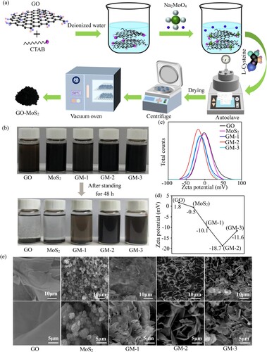
GO/MoS2 nanocomposite powder was prepared via a CTAB-assisted hydrothermal process (Huang et al. Citation2013). The specific preparation process of nanocomposite powder is shown in (a). In a typical batch, 20 mg GO was suspended in deionised water and then under ultrasound for half an hour to obtain a homogeneous suspension. After that, 0.3 g of CTAB was added to the above suspension under stirring for another 24 h to ensure that CTAB was absorbed on the surface of GO. Subsequently, 0.3 g of Na2MoO4 was weighed and then mixed with the solution, followed by stirring for 3 h. And then the mixture solution and 1 g of L-cysteine were transferred into a sealed stainless steel autoclave to conduct hydrothermal reaction. After cooling naturally to indoor temperature, the product was taken out, then centrifuged with deionised water and washed with ethyl alcohol for three times. Finally, it was dried in a vacuum oven at 80°C for 12 h to obtain black powder and the GO/MoS2 nanocomposite powder with 1:1 molar ratio of GO to MoS2 was designated as GM-1. Similarly, other nanocomposite powder was also prepared via the same procedure as above except that the addition of GO was different. Then GO/MoS2 with 2:1 (40 mg of GO) and 4:1 (80 mg of GO) molar ratio of GO to MoS2 were named as GM-2 and GM-3, respectively. The reason for the selection of GO to MoS2 with different molar ratios was that the synthesised GO/MoS2 nanocomposite with different molar ratios might exhibit different spatial structures for the studying of dispersion state (Chang and Chen Citation2011; Thi et al. Citation2020; Sarwar et al. Citation2021). For comparison, the pure MoS2 was synthesised under the similar hydrothermal process in the absence of GO and CTAB.
Figure 1. (a) The specific preparation process of GO-MoS2 nanocomposite powder. (b) The dispersion states of GO, MoS2, GM-1, GM-2 and GM-3 without PLLA in ethyl alcohol before and after 48 h at stationary conditions. (c) The micro morphologies of GO, MoS2, GM-1, GM-2 and GM-3 powder under SEM.
2.3. Synthesis of GO/MoS2-PLLA powder
The powder was prepared by means of adding 1.5 wt% GO, MoS2, GM-1, GM-2 and GM-3 into PLLA, respectively. In a specific case, 0.045 g of GM-1 and 2.955 g PLLA were suspended uniformly in 100 ml ethyl alcohol under the action of ultrasonication for 30 min, respectively. And then the above solution was mixed together, followed by stirring for 60 min. Afterwards, the prepared solution was centrifugated at 6000 rpm for 10 min and then placed in a drying cabinet for collecting GM-1/PLLA composite powder. The preparation of other compound powder was the same method as above.
2.4. Fabrication of composite scaffolds
The three-dimensional porous scaffold was fabricated via SLS system (Tino et al. Citation2020; Ge et al. Citation2020; Gu et al. Citation2020). Briefly, the composite powder was sintered selectively on the basis of predesigned model and turned into porous scaffolds with interconnected structure via layer by layer of construction, accompanying by 2.5 W of laser power, 120 mm/s of scanning speed and 0.6 mm of laser spot diameter, 0.3 mm of hatch distance and 0.2∼0.3 mm of powder layer thickness. These scaffolds loaded with 1.5 wt% GO, MoS2, GM-1, GM-2 and GM-3 were designated as 1.5GO/PLLA, 1.5MoS2/PLLA, 1.5GM-1/PLLA, 1.5GM-2/PLLA and 1.5GM-3/PLLA scaffolds, respectively.
2.5. Characterization
The microstructural morphologies and the dispersion states of GO and MoS2 were investigated by a scanning electron microscopy (SEM, Phenom-World BV, Netherlands). The powder specimen was dispersed in ethanol, and then the suspension was dripped onto the specimen table with conductive tape and finally dried. The block specimen was fixed to the specimen table directly through conductive tape. All specimens were sprayed with a layer of gold before being put into SEM and the microstructural morphologies were observed at 20 kV. The morphologies of nanocomposite powder and the distribution of the elements were observed under a transmission electron microscope (TEM, FEI, USA). The nanocomposite powder was ultrasonically dispersed in ethanol and then dropped onto a carbon-supported membrane (Zhongjingkeji, China). The specimen was mounted on the specimen holder of TEM after drying and observed at an acceleration voltage of 200 kV. The zeta potential of GO, MoS2, GM-1, GM-2 and GM-3 were determined in ethanol by a Zetasizer Nano (ZS90, Malvern, China) and all specimens were sonicated in ethanol for five minutes before testing. X-ray photoelectron spectroscopy (XPS, PHI-5000versaprobeIII, Japan) was used to characterise the elemental composition and atomic valence of specimens by using Al-Kα X-ray source in the scope of 0 eV to 1100 eV. All the peaks were fitted using CasaXPS program. Raman Spectrometer (Renishaw, UK) was used to study the chemical structure of specimens within the range of 250–1800 cm−1. X-ray diffraction (XRD) was utilised for investigating the crystalline phase and structure of nanocomposite by using a XRD diffractometer (Ultima IV, Japan) under the condition of Cu-Kα radiation and scanning rate of 8°/min.
Tensile properties were investigated via a universal testing machine (Zhongluchang, China) according to the GB/T 528-2009/ISO 37:2005 standard with a crosshead movement rate of 0.5 mm/min (Chi et al. Citation2019). The dumbbell-shaped scaffold specimens (14 × 2 × 2.5 mm3) were prepared for tensile experiments and each test was conducted five times. And the results were extracted and analyzed using Origin software (OriginLab Corporation, USA). After tensile experiments, the fracture morphologies of specimens were investigated via SEM, and the specimens were carpeted with gold in advance. What’s more, the dispersion states of nanomaterials in polymer matrix were studied by using a polarised optical microscope (POM, Batuo, China). The specimens were sliced and then heated up from indoor temperature to 200°C and kept for 100 s. After that, they were cooled naturally and the dispersion states were observed through a camera of POM.
2.6. Cell culture
Human osteoblast-like (MG-63) cells were purchased from Institute of Reproductive and Stem Cell Engineering (Xiangya Medical College, China) in order to investigate the cytocompatibility (Shuai, Chen, He, Qian, Shuai, Peng, Deng, and Wenjing, Citation2022; Gao, Zeng et al. Citation2022; Shuai, Yuan, Shuai, Qian, Yao, Xu, Peng, and Yang, Citation2022). They were cultured in Dulbecco’s Modified Eagle’s Medium (DMEM, Cellgro-Mediatech Inc., USA) equipped with 10% fetal bovine serum (FBS, Cellgro-Mediatech Inc., USA) and 1% penicillin/streptomycin antibiotics (Aladdin, China) under the circumstance of 37°C and 5% CO2. And the MG-63 cells were isolated by the enzyme digestion method. For all cell tests, 4–6 passaged cells were used and the cell density in suspension was 1 × 10⁵ cells mL−1. Before cell seeding, the cylindrical scaffolds (φ16 × 3 mm) were immersed in 70% ethanol for 30 min and then exposed to UV light for half an hour in order to achieve sterilization. Afterwards, the cells were seeded onto specimens in the culture medium at a density of 2 × 10⁵ cells/cm2 for 1, 3 and 5 d, and the medium was refreshed every two days. Before the observation of morphologies, the specimens were fetched out and washed three times by using phosphate buffer saline (PBS, Cellgro-Mediatech Inc., USA). Subsequently, the cells were fixed with 2.5% glutaraldehyde (Sigma-Aldrich, USA), washed with PBS and then dehydrated with graded ethanol. The specimens were dried at a vacuum oven and then sprayed with a film of gold before investigating the morphologies of cell adhesion under SEM. After that, the area of cell adhesion was calculated by means of PhotoShop software (Adobe Systems Inc., USA). Followed by cell cultivation, these specimens were used to perform fluorescence staining assay. To be specific, the specimens were exposed to 2 mM calcein AM (Sigma-Aldrich, USA) and 4 mM propidium iodide (Sigma-Aldrich, USA) for one hour in order to investigate live cells and dead cells, respectively. The fluorescence images were obtained by using a microscope equipped with a digital camera (IX51, Olympus, Japan), where live cells were stained green. The cell density was obtained by calculating the ratio of the number of cells to the image area. Five specimens were prepared in each group.
2.7. Statistical analysis
If not specified, all experiments in this study were performed three times. Statistical Package for the Social Science (SPSS, IBM Corporation, USA) software was used to analyze experimental data, which was indicated as mean ± standard error. p < 0.05 (*) and p < 0.01 (**) were considered significant difference and very significant difference in statistics, respectively.
3. Results and discussion
3.1. GO, MoS2 and GO/MoS2 nanocomposite characterization and analysis
The dispersion states of GO, MoS2 and GO/MoS2 powder suspended in ethyl alcohol after 48 h were investigated, and the results were exhibited in (b). All solutions exhibited a uniform and stable state immediately after ultrasound for 30 min while these solutions presented different dispersion states after standing for 48 h. For GO and MoS2 suspension, the GO and MoS2 finally settled down on the bottom and the limpid supernatant was observed obviously, which was ascribed to the aggregations of GO and MoS2. It could be observed that GM-1, GM-2 and GM-3 solutions presented relatively improved dispersibility compared with the pure GO and MoS2 solutions. What’s more, some sediments could be both observed in the GM-1 and GM-3 solutions but not in the GM-2 solution. And the colours of the GM-1 and GM-3 solution changed from dark to shallow because the excess MoS2 and GO resulted in poor dispersibility, respectively. By contrast, it could be observed that the GM-2 suspension still maintained a relatively uniform and stable state and few precipitates appeared at the bottom of the solution, which indicated a good dispersion state. The zeta potential could be used as an index to characterise the repulsive effect between nanoparticles, and the higher positive potential or the lower negative potential, which meant the better dispersion stability of the nanoparticles (Krishnakumar and Elansezhian Citation2022; Gupta et al. Citation2021; Abedi, Fangueiro, and Correia Citation2020). As shown in (c–d), the zeta potential of GO, MoS2, GM-1, GM-2 and GM-3 were 1.8 mV, −0.5 mV, −10.1 mV, −18.7 mV and −11.6 mV, respectively. It could be inferred that GM-1, GM-2 and GM-3 were better dispersed than GO and MoS2, and GM-2 had the best dispersion. It meant that the in-situ growth of MoS2 on GO could improve dispersion states, and the ratio of GO to MoS2 in GM-2 was relatively appropriate compared with other ratios of GO to MoS2, which was in favour of better dispersibility.
The micromorphologies of GO, MoS2 and GO/MoS2 powder were observed, as presented in (e). The pristine GO exhibited a typical laminated structure with curled and corrugated morphologies and stacked together. And from high magnification image, the smooth surface could be observed. While as-synthesised MoS2 consisted of spherical particles whose average diameter was about 2 μm, and a large number of agglomerations were significantly observed. When GO and CTAB were introduced into the synthetic process of MoS2, it could be found that spherical structure of MoS2 was transformed into nanosheet structure. For GM-1 powder, there were large-scale MoS2 nanosheets which tightly stacked together due to the excess precursor of Mo. It could be observed from GM-2 powder that MoS2 nanosheets were uniformly arranged on the surface of GO, and the phenomenon of agglomeration of MoS2 was significantly improved on account of the appropriate ratio of GO to MoS2. What’s more, for GM-3 powder, it was also found that MoS2 could be dispersed well while there existed some aggregations due to the addition of excess GO. From the above results, it could be concluded that the phenomena of agglomerations were significantly restrained, and the morphologies of MoS2 were greatly influenced through controlling the ratios of GO to MoS2 (Chen et al. Citation2021).
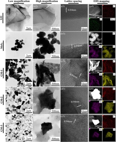
The TEM images and EDS mapping images of GO, MoS2 and GO/MoS2 powder were provided for further investigation of microstructure, as shown in . It could be observed from (a) that the pure GO presented typical lamellar structure and smooth surface accompanied with wrinkle morphology, and there existed some GO nanosheets stacked together. The lattice spacing of adjacent nanosheets was approximately 0.84 nm, which was corresponding to the (002) plane of GO (Mohamed et al. Citation2019), and the C and O elements were observed to disperse uniformly. From (b), the pure MoS2 exhibited spherical appearance, which was corresponding to the results of SEM, and MoS2 was proved to stack together. For the GO/MoS2 nanocomposite powder, it could be found that MoS2 nanosheets exhibited lamellar structure, which were in situ grown vertically on the surface of GO, and lattice spacing of adjacent MoS2 nanosheets was approximately 0.94 nm, which was corresponding to (002) plane (Zhang and Liang Citation2018). For GM-1, excess MoS2 was observed to generate some agglomerations, which was shown as large areas of black images in (c). And the Mo and S elements were observed to disperse ununiformly. From (d), MoS2 nanosheets were grown uniformly on the surface of GO without significant aggregations under the appropriate ratio of MoS2 to GO. And the C, Mo and S elements could be observed to distribute uniformly from EDS mapping results. In comparison, from (e), it could be found that the number and area of MoS2 decreased relatively and the area of GO increased, which produced some agglomerations due to the excess amount. From the above results, it could be concluded that MoS2 nanosheets were in situ grown vertically onto GO nanosheets. Besides, the appropriate ratio of MoS2 to GO played an important role in the uniform dispersion of MoS2/GO because excess MoS2 and GO both resulted in the generation of agglomerations (Chang and Chen Citation2011), respectively, which was corresponding to the results of SEM.
Figure 2. TEM images at different magnifications, HERTEM images and EDS mapping images of pure GO (a1-a4), pure MoS2 (b1-b4), GM-1 (c1-c4), GM-2 (d1-d4) and GM-3 (e1-e4) powder.
XPS was conducted to characterise the chemical composition and atomic valence of the GO, MoS2 and GO/MoS2 powder, and the results were presented in (a–c). The full-scan spectra of the GO, MoS2 and GO/MoS2 powder were exhibited in (a). GO possessed two typical peaks of C1s and O1s, and MoS2 possessed corresponding peaks of Mo3d and S2p. The survey spectrum of the GO/MoS2 powder showed the presence of C, O, Mo and S elements, which reached a preliminary conclusion that MoS2 was successfully synthesised on the surface of GO. Besides, the narrow scans of Mo3d and S2p in the GO/MoS2 powder were investigated for further proof. In the high-resolution spectra of Mo3d, there existed two strong characteristic peaks assigned to Mo3d3/2 (232.4 eV) and Mo3d5/2 (229.2 eV), respectively, which revealed the characteristic +4 oxidation state of Mo. What’s more, two weak peaks at 233.6 eV and 226.7 eV were attributed to Mo6+ and S2s, respectively. Similarly, the two feature peaks of S2p1/2 and S2p3/2 were observed at 163.3 and 162.2 eV, respectively, as presented in (c), corresponding to binding energy of S2− (Wang et al. Citation2019; Zou et al. Citation2019; Ye et al. Citation2016). Therefore, the above results of XPS manifested that MoS2 was successfully grown on the surface of GO.
Figure 3. (a) The full-scan XPS spectra of GO, MoS2 and GO/MoS2 powder. (b) The narrow scan spectra of Mo3d in GO/MoS2 powder. (c) The narrow scan spectra of S2p in GO/MoS2 powder. (d–e) Raman spectra of GO, MoS2 and GO/MoS2 powder. (f) XRD spectra of GO, MoS2, GM-1, GM-2 and GM-3 powder.
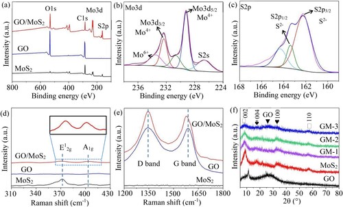
Raman spectra related to the GO, MoS2 and GO/MoS2 powder were investigated, as presented in (d-e). For pure MoS2 powder, there were two peaks at 374 cm−1 and 404 cm−1, corresponding to E12g and A1g vibration modes, respectively, which were ascribed to the in-plane vibration of Mo-S atoms and the out-of-plane vibration of Mo-S atoms, respectively (Wang et al. Citation2016). What’s more, it could be observed that there existed two typical characteristic peaks of GO, which were attributed to the D band and G band at 1345 cm−1 and 1589 cm−1, respectively (Lee et al. Citation2021). The D band was related to vibration of sp3-bonded C atoms, while G band arose from the vibration of sp2 carbon atoms, representing the structure ordering. For the GO/MoS2 nanocomposite powder, it could be found that there existed two peaks at 374 and 404 cm−1 attributing to MoS2 while the other two typical peaks at 1346 and 1578 cm−1 belonged to GO, respectively, which demonstrated that MoS2 was successfully in situ grown on the surface of GO. In addition, G band was shifted from 1589 cm−1 to 1578 cm−1, revealing the chemical doping of carbon material and the formation of dyadic bonding between GO and MoS2 (Thangappan et al. Citation2016). It could be noted that the value of ID/IG (∼1.10) of the GO/MoS2 powder increased compared with that of pure GO powder (∼1.01), which indicated there emerged some defects and disordered structures (Xie et al. Citation2016). In general, it could be concluded from the above results that MoS2 was successfully grown onto GO under the condition of hydrothermal reaction.
XRD spectroscopy was used to investigate the crystalline phase and structure of the GO, MoS2 and GO/MoS2 powder with different ratios of MoS2 to GO, as shown in (f). It could be observed that there existed two diffraction peaks of GO at 11.8° and 26.9°, which were corresponding to (001) and (002) planes, respectively, and the lattice spacing of adjacent nanosheets was approximately 0.84 nm corresponding to (002) plane. For the pure MoS2 powder, the typical characteristic peaks at 8.8°, 17.4°, 33.2° and 57.0° were ascribed to (002), (004), (100) and (110) planes, respectively. GO/MoS2 nanocomposites powder possessed similar diffraction peaks to pure MoS2, which indicated that they possessed similar crystalline structure to MoS2. What’s more, the diffraction peak of them corresponding to (002) plane at 8.8° indicated a d-spacing of 0.94 nm, which corresponded with the results of TEM. And the intensity of relevant diffraction peaks was weakened monotonously accompanied by reduced proportions of MoS2. Besides, the newly appeared diffraction peak of GM-3 at 27.4° was ascribed to GO, which suggested that the content of GO was excessive, resulting in some agglomerations (Qin et al. Citation2015; Wang et al. Citation2018; Lin et al. Citation2020). The above results of XRD demonstrated that the synthetic MoS2 possessed good crystal structure, and MoS2 was successfully in situ grown on GO. Besides, the ratio of MoS2 to GO played a crucial part in the dispersion of GO/MoS2 nanocomposite.
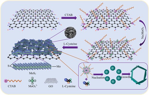
The mechanism diagram of the in-situ growth of MoS2 nanosheets onto GO nanosheets was illustrated in . It was well known that GO carried negative charge in aqueous solution due to plentiful oxygenated groups including carboxyl and hydroxyl. Therefore, CTAB served as a typical cationic surfactant, containing positively charged head groups, which could be absorbed on the surface of GO through electrostatic interaction. It endowed GO with positive charge in order to overcome charge incompatibility between GO and anion. Afterwards, molybdate ion (MoO42-) could be attracted on CTA+-GO via electrostatic action and then gradually nucleated and grew into MoS2 nanosheets in the presence of L-cysteine, which acted as sulphur source and reducing agent. Finally, MoS2 nanosheets were vertically, selectively and uniformly arranged onto the surface of GO nanosheets.
Figure 4. The mechanism diagram of the MoS2 nanosheets in situ grown on both sides of GO nanosheets via CTAB-assisted hydrothermal process.
3.2. Dispersion of GO, MoS2 and GO/MoS2 in the matrix
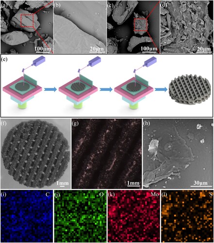
The morphologies of PLLA, GM/PLLA powder and GM/PLLA scaffold were investigated through SEM. The PLLA powder possessed irregular shape with average particle size of ∼150 μm as shown in (a), and it could be found from high magnified image that the surface had a smooth condition ((b)). For the GM/PLLA powder, the surface of PLLA became relatively rough, and there existed some GO/MoS2 nanosheets that adhered to the surface of PLLA in (c–d). The fabrication process of GM/PLLA scaffold was presented in (e), and the porous scaffold was obtained via sintering layer by layer according to the given model. From the top view of the scaffold as shown in (f), the scaffold appeared black in appearance with a cylindrical shape and the diameter was approximately 16 mm. It was observed under SEM from (f–g) that the interior of the scaffold was an interconnected pore structure, which could facilitate nutrient exchange and promote cell proliferation (Shuai et al. Citation2022). So, the scaffold was prospective to apply in bone tissue engineering. The EDS results were exhibited in (i–l). The results indicated that the C, O, Mo and S elements were uniformly distributed, which suggested the good dispersion of GO/MoS2 nanosheets on the PLLA scaffold.
Figure 5. The morphologies of the PLLA (a), GM/PLLA powder (c) and their corresponding high magnified images (b, d). (e) The fabrication process of the GM/PLLA scaffold via SLS. (f) The top view of the scaffold. (g) The optical microscope (OM) image of the scaffold. (h) The SEM images of the surface of scaffold. (i-l) The EDS elemental mappings of C, O, Mo and S signals.
The dispersibility of nanomaterials played a crucial part in the properties of composite materials (Teng et al. Citation2021), so the dispersion states of nanomaterials in PLLA matrix were investigated, and the results were presented in . There were a number of big dark masses stacked together in the 1.5GO/PLLA scaffold under POM, which indicated that GO nanosheets formed large-scale agglomerations because of the high content of GO. Similarly, there also existed numerous agglomerations of MoS2, which were observed to cover most of the area from the high magnification image of the 1.5MoS2/PLLA scaffold. It could be concluded that the GO and MoS2 were prone to generate irreversible aggregations in PLLA matrix, respectively, under the circumstance of high content. After the in-situ growth of MoS2 onto GO, the dispersibility of GO/MoS2 nanocomposite was also conducted. From the 1.5GM-1/PLLA scaffold, it could be observed that the phenomenon of aggregation was alleviated while the MoS2 still formed some continuous agglomerations due to the relatively high proportion. Compared with that, it could be observed that the dispersibility was significantly improved after increasing ratio of GO and GM-2 dispersed uniformly in the PLLA matrix. What’s more, for the 1.5GM-3/PLLA scaffold, there existed large chunks of aggregations reappeared, which was ascribed to excess GO stacked together. From the above results, it could be demonstrated that the dispersion states of GO and MoS2 could be improved significantly by means of in-situ growth of MoS2 onto GO. Besides, the ratio of GO to MoS2 played a crucial part in their dispersibility in PLLA matrix. For GO/MoS2 nanocomposite, the excessive GO and MoS2 both resulted in poor dispersion and serious aggregations and only appropriate proportion of GO and MoS2 could contribute to good dispersibility in the PLLA matrix.
Figure 6. The dispersion states of the 1.5GO, 1.5MoS2, 1.5GM-1, 1.5GM-2 and 1.5GM-3 powder in the PLLA matrix under POM and SEM, respectively.
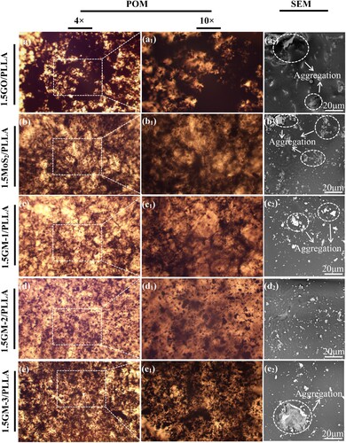
The dispersibility could also be investigated from the results of SEM, and it could be observed that the surface of PLLA had a relatively smooth condition. For the 1.5GO/PLLA scaffold, there were some large GO nanosheets which were stacked together, forming serious agglomerations. Similarly, it could be significantly observed that the agglomerations of MoS2 were formed in PLLA matrix. In contrast, the phenomenon of the aggregations of them could be improved by introducing MoS2 on GO. From the 1.5GM-1/PLLA scaffold, there existed a few agglomerations of GM in the PLLA matrix due to excess MoS2 although it showed better dispersion compared with the 1.5GO/PLLA and 1.5MoS2/PLLA scaffolds. Besides, for the 1.5GM-2/PLLA scaffold, GM presented a uniform dispersion state and no obvious aggregations were observed because of the appropriate ratio of MoS2 to GO. There were also some excess GO nanosheets stacked together in the 1.5GM-3/PLLA scaffold, indicating relatively decreased dispersibility. Therefore, it could be concluded that the introduction of MoS2 on GO and the appropriate ratio of MoS2 to GO both had positive effects on their dispersion in PLLA matrix (Song et al. Citation2017).
3.3. Mechanical properties
The tensile properties of scaffolds were investigated, as shown in . It could be observed that the dumbbell-shaped specimens were broken after tensile experiments. For the pure PLLA scaffold, it could present strength of 6.32 MPa and modulus of 921 MPa, respectively, which showed the lowest tensile properties. The strength and modulus of the 1.5GO/PLLA and 1.5MoS2/PLLA scaffolds were slightly improved due to the addition of GO and MoS2, while the improvement was inconspicuous because of the excessive contents, compared with pure PLLA scaffold. After in-situ growth of MoS2 onto GO, tensile properties of the scaffold were significantly improved. It could be observed that the tensile strength and modulus of the 1.5GM-1/PLLA scaffold showed 8.35 MPa and 1163 MPa, respectively, which were considerably higher than that of the PLLA scaffold (p < 0.05). And the tensile strength and modulus of the 1.5GM-1/PLLA scaffold were increased by 32% and 26%, respectively, compared with pure PLLA scaffold. What’s more, 1.5GM-2/PLLA scaffold presented the best tensile properties, whose strength and modulus were considerably higher than that of the PLLA scaffold (p < 0.01). The strength and modulus of the 1.5GM-2/PLLA scaffold was 10.2 and 1461 MPa, respectively, increasing by 61% and 58%, respectively, compared with pure PLLA scaffold. For 1.5GM-3/PLLA scaffold, the tensile properties were declined compared with the 1.5GM-2/PLLA scaffold, due to the addition of excess GO. presented a comparison of the tensile strength of our work with that of others on the PLLA and PLLA composite scaffolds (Prabhakaran, Venugopal, and Ramakrishna Citation2009; Zhou et al. Citation2017; Jing et al. Citation2020; Öztatlı and Ege Citation2017; Liao, Li, and Tjong Citation2019; Adithya et al. Citation2020). It could be observed that the tensile strength of the GO/PLLA, MoS2/PLLA and GM-2/PLLA scaffolds were significantly higher than that of the PLLA scaffold. Previous studies have indicated that the addition of appropriate amount of GO or MoS2 could improve the mechanical properties of the scaffold due to the unique flake structures, large surface areas and excellent mechanical properties of GO and MoS2 (Guo et al. Citation2022). Furthermore, the tensile strength of the GM-2/PLLA scaffold was higher than that of the GO/PLLA and MoS2/PLLA scaffolds. The reason was that GO or MoS2 had a high specific surface area and strong interaction force, which were prone to agglomeration in the polymer matrix, resulting in reduced enhancement efficiency (Wu, Yin et al. Citation2021; Lin et al. Citation2021). In the present study, MoS2 nanosheets were in situ synthesised vertically and uniformly on the surface of GO nanosheets to obtain GM-2, which formed steric hindrance effect to support the dispersion of GO. It allowed GM-2 to have better dispersion properties than GO and MoS2 in the matrix, which could fully exert the mechanical strengthening effect of GO and MoS2 to enhance the mechanical properties of the scaffold. Through the above tensile results, tensile properties of the scaffold were significantly enhanced by means of in-situ growth of MoS2 onto GO, and the appropriate ratio of GO to MoS2 also played a crucial part in the tensile properties of the scaffold. Because the 1.5GM-2/PLLA scaffold had the best mechanical properties in all of the above scaffolds, and subsequent experiments were only conducted to test and analyze the 1.5GM-2/PLLA scaffold.
Figure 7. (a) The tensile specimens clamped with tongs of the universal testing machine. (b) The tensile specimens before and after tensile experiment. (c–d) The stress-strain curves, tensile strength and modulus of the PLLA, 1.5GO/PLLA, 1.5MoS2/PLLA, 1.5GM-1/PLLA, 1.5GM-2/PLLA and 1.5GM-3/PLLA scaffold specimens. * represents statistical difference (*p < 0.05, **p < 0.01) compared with the PLLA scaffold.
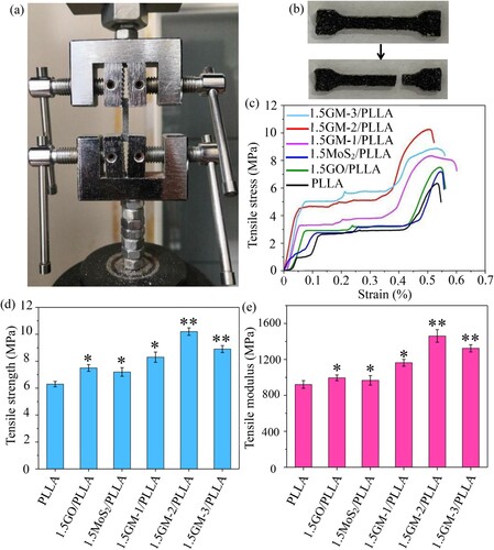
Table 1. Tensile strength of PLLA, GO/PLLA, MoS2/PLLA and GM-2/PLLA.
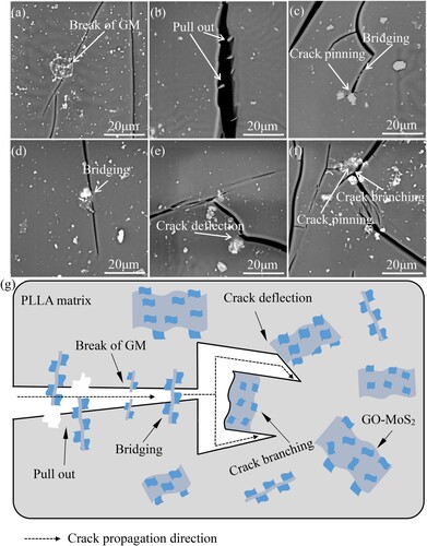
The crack propagation, which was generated via the Vickers indentation method at the load of 9.8 N, was used to investigate the influence of GM-2 on the scaffold, and the morphologies were presented in . GM-2 was broken under the condition of crack propagation, which required a lot of energy. For the morphology of pull out, GM-2 was pulled out of the PLLA matrix, which enhanced the interfacial connection between them (Florek et al. Citation2021). It was observed that there existed some GM-2 at the destination of the crack because the energy was insufficient for crack propagation, which was referred as crack pinning (Fan et al. Citation2021). What’s more, there existed GM-2 bridges on the surface to connect the crack, restricting the interface slip and delaying further propagation (Ghazanlou, Ghazanlou, and Ashraf Citation2021). Crack was generally extended in a monotonous direction with no deflection while the crack would be obstructed and then deviate from the original direction under the condition of encountering GM-2, which resulted in consuming more energy for crack propagation. Similarly, the extended crack branched in the way of river-delta when encountering GM-2 at the end of crack tip (Abazari, Shamsipur, and RezaBakhsheshi-Rad Citation2021). The corresponding crack propagation model was presented in (g). It could be concluded that crack propagation caused by the above results would consume more fracture energy in order to effectively enhance the tensile properties and fracture toughness.
Figure 8. (a–f) SEM images of crack propagation in the 1.5GM-2/PLLA scaffold. (g) The corresponding crack propagation model.
3.4. Cytocompatibility
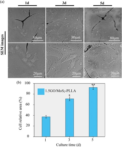
The results of fluorescence images could be used to elucidate the cell behaviour of 1.5GM-2/PLLA scaffold (the PLLA scaffold as control). As shown in (a), it could be seen that the number of living cells on both scaffolds gradually increased with the increase of culture time, and only few dead cells appeared at each time point. From (b–c), the PLLA scaffold and 1.5GM-2/PLLA scaffold exhibited cell density of 819 cells/mm2 and 926 cells/mm2 at 5 d, respectively, which was considerably much higher than that of the PLLA scaffold and 1.5GM-2/PLLA scaffold at 1 d (p < 0.01), suggesting that both scaffolds promoted cell proliferation (Deng et al. Citation2022; Qi, Liao, Shuai, Pan, Qian, Peng, and Shuai, Citation2022). In addition, after the same time of culture, there were slightly more live cells on the 1.5GM-2/PLLA scaffold than on the pure PLLA scaffold, which might be due to a small amount of GO contained in the 1.5GM-2/PLLA scaffold. In previous studies, it was found that adding a small amount of GO to the scaffold could promote cell proliferation. The MG-63 cells were cultivated on the 1.5GM-2/PLLA scaffold for 1, 3 and 5 d to investigate morphological features. As shown in (a), it could be obviously observed that there existed many individual spherical cells adhered on the scaffold after 1 d of culture. For 3 d, cells gradually expanded and then grew into fusiform shape, and the filopodia was newly appeared. After culturing for 5 d, the cells continued expanding widely and eventually reached confluence to form a fused cell layer. The shape of cells was transformed into polygonal and few spherical cells could be observed. What’s more, the cell relative area gradually increased with increasing incubation time and reached a maximum of 92% after 5 d of culture as shown in (b), which was considerably much higher than that of the 1.5GM-2/PLLA scaffold at 1 d (p < 0.01). It could be concluded that the cells on the 1.5GM-2/PLLA scaffold possessed benign adhesion and growth. It could be demonstrated that the 1.5GM-2/PLLA scaffold possessed favourable cytocompatibility, which was expected to be applied in the field of bone implants (Sharma et al. Citation2021; Wu, Zou et al. Citation2021; Qi, Wang, Shuai, Peng, and Shuai. Citation2022).
Figure 9. (a) Fluorescence images of MG-63 cells cultivated on the PLLA scaffold and 1.5GM-2/PLLA scaffold for 1, 3 and 5 d. (b) Live cells density of MG-63 cells cultivated on the PLLA scaffold for 1, 3 and 5 d. (c) Live cells density of MG-63 cells cultivated on the 1.5GM-2/PLLA scaffold for 1, 3 and 5 d. * represents statistical difference (*p < 0.05, **p < 0.01) compared with the PLLA scaffold or 1.5GM-2/PLLA scaffold at 1 d.
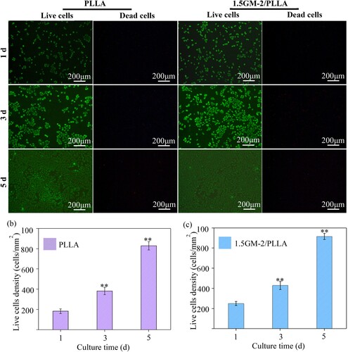
Figure 10. (a) SEM images of MG-63 cells cultivated on the 1.5GM-2/PLLA scaffold for 1, 3 and 5 d. (b) Cell relative area of MG-63 cells cultivated on the 1.5GM-2/PLLA scaffold for 1, 3 and 5 d. * represents statistical difference (*p < 0.05, **p < 0.01) compared with the 1.5GM-2/PLLA scaffold at 1 d.
4. Conclusions
In this study, MoS2 nanosheets were in-situ grown onto the surface of GO nanosheets to construct a co-dispersion nanosheets/nanosheets system via CTAB-assisted hydrothermal process for improving their dispersion. And then they were added into PLLA matrix to fabricate composite scaffold by means of SLS. In the GO-MoS2 nanostructure, MoS2 nanosheets were selectively grown on GO to achieve uniform dispersion, and then the growth of MoS2 nanosheets could form steric hindrance effect to hinder the aggregations of GO nanosheets, leading to better dispersion states and reinforcement efficiency. According to tensile experimental results, the GO/MoS2-PLLA scaffold exhibited the best tensile strength and modulus, whose values were 10.2 and 1461 MPa, respectively, which enhanced significantly compared with the GO/PLLA and MoS2/PLLA scaffolds, owing to improved dispersibility of nanomaterials in the PLLA matrix. What’s more, the reinforcement mechanisms of tensile properties involved crack deflection, crack bridging, crack pinning and pulling out of GO/MoS2. In addition, the GO/MoS2-PLLA scaffold possessed benign cytocompatibility, indicating hopeful applications for bone implants.
Disclosure statement
No potential conflict of interest was reported by the author(s).
Additional information
Funding
Notes on contributors
Pei Feng
Pei Feng is an associate professor in the School of Mechanical and Electrical Engineering at Central South University. He is engaged in the research of additive manufacturing, and bone repair materials. He has published more than 30 Sci papers in Adv Sci, Bioact Mater, etc.
Saipu Shen
Saipu Shen is a postgraduate of the School of Mechanical and Electrical Engineering at Central South University. His current research focuses on laser additive manufacturing and bone repair materials.
Liuyimei Yang
Liuyimei Yang is currently the assistant research fellow at the Ganjiang Innovation Academy of Chinese Academy of Science in China. Her research interest mainly focuses on granular materials, numerical simulation, powder mixing, the addictive manufacturing and the multi-material 3D printing.
Ye Kong
Ye Kong is a postgraduate of the School of Mechanical and Electrical Engineering at Central South University. His current research focuses on laser additive manufacturing and bone repair materials.
Sheng Yang
Sheng Yang is a professor currently working at Shenzhen University. His research centres on the differentiation mechanism of human totipotent stem cells into oocytes and the mechanism of stem cells repairing endometrium to improve clinical pregnancy outcomes.
Cijun Shuai
Cijun Shuai is a professor in Central South University, and Jiangxi University of Science and technology. He has been engaged in the research of biological additive manufacturing. Moreover, he has published over 200 research papers in journals including Nano Energy, Adv Sci, etc.
References
- Abazari, Somayeh, Ali Shamsipur, and Hamid RezaBakhsheshi-Rad. 2021. “Reduced Graphene Oxide (RGO) Reinforced Mg Biocomposites for Use as Orthopedic Applications: Mechanical Properties, Cytocompatibility and Antibacterial Activity.” Journal of Magnesium and Alloys, doi:10.1016/j.jma.2021.09.016.
- Abdelhalim, Abdelsattar O. E., Anatolii A. Meshcheriakov, Dmitrii N. Maistrenko, Oleg E. Molchanov, Sergei V. Ageev, Daria A. Ivanova, Nailia R. Iamalova, et al. 2021. “Semenov, Graphene Oxide Enriched with Oxygen-Containing Groups: On the way to an Increase of Antioxidant Activity and Biocompatibility.” Colloids and Surfaces B: Biointerfaces 210: 112232. doi:10.1016/j.colsurfb.2021.112232.
- Abedi, M., R. Fangueiro, and A. G. Correia. 2020. “An Effective Method for Hybrid CNT/GNP Dispersion and Its Effects on the Mechanical, Microstructural, Thermal, and Electrical Properties of Multifunctional Cementitious Composites.” Journal of Nanomaterials 20: 6749150. doi:10.1155/2020/6749150.
- Achagri, Ghizlane, Younes Essamlali, Othmane Amadine, Mohamed Majdoub, Achraf Chakir, and Mohamed Zahouily. 2020. “Surface Modification of Highly Hydrophobic Polyester Fabric Coated with Octadecylamine-Functionalized Graphene Nanosheets.” RSC Advances 10 (42): 24941–24950. doi:10.1039/D0RA02655G.
- Adithya, S. P., D. S. Sidharthan, R. Abhinandan, K. Balagangadharan, and N. Selvamurugan. 2020. “Nanosheets-incorporated Bio-composites Containing Natural and Synthetic Polymers/Ceramics for Bone Tissue Engineering.” International Journal of Biological Macromolecules 164: 1960–1972. doi:10.1016/j.ijbiomac.2020.08.053.
- Arslan, Kağan Arslan, Çelik Ekin, Alkan Funda, and Demirbilek Murat. 2021. “GO Containing PHBHX Bone Scaffold: GO concentration and in Vitro Osteointegration.” Polymer Bulletin 79 (8): 5939–5954. doi:10.1007/s00289-021-03788-6.
- Chang, Kun, and Weixiang Chen. 2011. “L-cysteine-assisted Synthesis of Layered MoS2/Graphene Composites with Excellent Electrochemical Performances for Lithium ion Batteries.” ACS Nano 5 (6): 4720–4728. doi:10.1021/nn200659w.
- Chen, Ling, Yu Liu, Zongnan Deng, Hao Jiang, and Chunzhong Li. 2021. “Edge-enriched MoS2@C/rGO Film as Self-Standing Anodes for High-Capacity and Long-Life Lithium-Ion Batteries.” Science China Materials 64 (1): 96–104. doi:10.1007/s40843-020-1348-y.
- Chen, Hai, Tianbing Song, Linbin Tang, Xiaoming Pu, Zhi Li, Qunjie Xu, Haimei Liu, YongGang Wang, and Yongyao Xia. 2020. “In-situ Growth of Vertically Aligned MoS2 Nanowalls on Reduced Graphene Oxide Enables a Large Capacity and Highly Stable Anode for Sodium ion Storage.” Journal of Power Sources 445: 227271. doi:10.1016/j.jpowsour.2019.227271.
- Chen, Kexin, Dong Yang, Yongqian Shi, Yuezhan Feng, Libi Fu, Chuan Liu, Ming Chen, and Fuqiang Yang. 2021. “Synergistic Function of N-P-Cu Containing Supermolecular Assembly Networks in Intumescent Flame Retardant Thermoplastic Polyurethane.” Polymers for Advanced Technologies 32 (11): 4450–4463. doi:10.1002/pat.5448.
- Chi, Qingguo, Meng Yang, Tiandong Zhang, and Changhai Zhang. 2019. “Investigation of Electrical and Mechanical Properties of Silver-Hexagonal Boron Nitride/EPDM Composites.” Journal of Materials Science: Materials in Electronics 30 (14): 13321–13329. doi:10.1007/s10854-019-01699-x.
- Deng, Fang, Ping Wu, Guowen Qian, Yang Shuai, Lemin Zhang, Shuping Peng, Cijun Shuai, and Guoyong Wang. 2022. “Silver-decorated Black Phosphorus: A Synergistic Antibacterial Strategy.” Nanotechnology 33 (24): 245708. doi:10.1088/1361-6528/ac5aee.
- Dewapriya, M. A. N., and Shaker Abdel Meguid. 2018. “Tailoring Fracture Strength of Graphene.” Computational Materials Science 141: 114–121. doi:10.1016/j.commatsci.2017.09.005.
- Dhinakaran, Veeman, Manimangalam Lavanya, K. Vigneswari, M. Ravichandran, and M. D. Vijayakumar. 2020. “Review on Exploration of Graphene in Diverse Applications and Its Future Horizon.” Materials Today: Proceedings 27: 824–828. doi:10.1016/j.matpr.2019.12.369.
- Fan, Jie, Jiping Yang, Hong Li, Junpeng Tian, Meng Wang, and Yunfeng Zhao. 2021. “Cryogenic Mechanical Properties of Graphene Oxide/Epoxy Nanocomposites: Influence of Graphene Oxide with Different Oxidation Degrees.” Polymer Testing 96: 107074. doi:10.1016/j.polymertesting.2021.107074.
- Feng, Pei, Kai Wang, Yang Shuai, Shuping Peng, Yongbin Hu, and Cijun Shuai. 2022. “Hydroxyapatite Nanoparticles in Situ Grown on Carbon Nanotube as a Reinforcement for Poly (ϵ-Caprolactone) Bone Scaffold.” Materials Today Advances 15: 100272. doi:10.1016/j.mtadv.2022.100272.
- Florek, Paulina, Magdalena Król, Piotr Jeleń, and Włodzimierz Mozgawa. 2021. “Carbon Fiber Reinforced Polymer Composites Doped with Graphene Oxide in Light of Spectroscopic Studies.” Materials 14 (8): 1835. doi:10.3390/ma14081835.
- Gao, Mingzhen, Bing Liu, Xinyu Zhang, Yuanming Zhang, Xianbo Li, and Guangting Han. 2022. “Ultrathin MoS2 Nanosheets Anchored on Carbon Nanofibers as Free-Standing Flexible Anode with Stable Lithium Storage Performance.” Journal of Alloys and Compounds 894: 162550. doi:10.1016/j.jallcom.2021.162550.
- Gao, Chengde, Zihao Zeng, Shuping Peng, and Cijun Shuai. 2022. “Magnetostrictive Bulk Fe-Ga Alloys Prepared by Selective Laser Melting for Biodegradable Implant Applications.” Materials & Design 220: 110861. doi:10.1016/j.matdes.2022.110861.
- Ge, Qi, Zhiqin Li, Zhaolong Wang, Kavin Kowsari, Wang Zhang, Xiangnan He, Jianlin Zhou, and Nicholas X Fang. 2020. “Projection Micro Stereolithography based 3D Printing and Its Applications.” International Journal of Extreme Manufacturing 2 (2): 022004. doi:10.1088/2631-7990/ab8d9a.
- Ghazanlou, Siavash Imanian, Siamak Imanian Ghazanlou, and Warda Ashraf. 2021. “Improvement in the Physical and Mechanical Properties of the Cement-Based Composite with the Addition of Nanostructured BN–Fe3O4 Reinforcement.” Scientific Reports 11 (1): 1–13. doi:10.1038/s41598-021-98800-4.
- Gnanasekar, Pitchaimari, Heyu Chen, Nicole Tratnik, Martin Feng, and Ning Yan. 2021. “Enhancing Performance of Phosphorus Containing Vanillin-Based Epoxy Resins by P-N non-Covalently Functionalized Graphene Oxide Nanofillers.” Composites Part B: Engineering 207: 108585. doi:10.1016/j.compositesb.2020.108585.
- Gu, Dongdong, Meng Guo, Hongmei Zhang, Yixuan Sun, Rui Wang, and Lei Zhang. 2020. “Effects of Laser Scanning Strategies on Selective Laser Melting of Pure Tungsten.” International Journal of Extreme Manufacturing 2 (2): 025001. doi:10.1088/2631-7990/ab7b00.
- Guo, Lifang, Xiaoyu Li, Wenxiang Li, Chenchen Gou, Meifang Zheng, Yong Zhang, Zhiyu Chen, and Yu Hong. 2022. “High-sensitive Humidity Sensor Based on MoS2/Graphene Oxide Quantum dot Nanocomposite.” Materials Chemistry and Physics 287: 126146. doi:10.1016/j.matchemphys.2022.126146.
- Gupta, Deepika, Vishnu Chauhan, and Rajesh Kumar. 2020. “A Comprehensive Review on Synthesis and Applications of Molybdenum Disulfide (MoS2) Material: Past and Recent Developments.” Inorganic Chemistry Communications 121: 108200. doi:10.1016/j.inoche.2020.108200.
- Gupta, N., S. M. Gupta, and S. K. Sharma. 2021. “Synthesis, Characterization and Dispersion Stability of Water-based Cu–CNT Hybrid Nanofluid Without Surfactant.” Microfluidics and Nanofluidics 25 (2): 1–14. doi:10.1007/s10404-021-02421-2.
- Huang, Guochuang, Tao Chen, Weixiang Chen, Zhen Wang, Kun Chang, Lin Ma, Feihe Huang, Dongyun Chen, and Jim Yang Lee. 2013. “Graphene-Like MoS2/Graphene Composites: Cationic Surfactant-Assisted Hydrothermal Synthesis and Electrochemical Reversible Storage of Lithium.” Small 9 (21): 3693–3703. doi:10.1002/smll.201300415.
- Jing, Zhu, Dexin Tang, Zihan Lu, Zhiying Xin, Jun Song, Jinmin Meng, Jian R. Lu, Zhi Li, and Jiashen Li. 2020. “Ultrafast Bone-Like Apatite Formation on Highly Porous Poly (l-Lactic Acid)-Hydroxyapatite Fibres.” Materials Science and Engineering: C 116: 111168. doi:10.1016/j.msec.2020.111168.
- Krishnakumar, V., and R. Elansezhian. 2021. “Dispersion Stability of Zinc Oxide Nanoparticles in an Electroless Bath with Various Surfactants.” Materials Today: Proceedings 51: 369–373. doi:10.1016/j.matpr.2021.05.467.
- Krishnakumar, V., and R. Elansezhian. 2022. “Dispersion Stability of Zinc Oxide Nanoparticles in an Electroless Bath with Various surfactants.” Materials Today: Proceedings 51: 369–373. doi:10.1016/j.matpr.2021.05.467.
- Lee, A. Young, Kihyuk Yang, Nguyen Duc Anh, Chulho Park, Seung Mi Lee, Tae Geol Lee, and Mun Seok Jeong. 2021. “Raman Study of D* Band in Graphene Oxide and Its Correlation with Reduction.” Applied Surface Science 536: 147990. doi:10.1016/j.apsusc.2020.147990.
- Liao, Chengzhu, Yuchao Li, and Sie Chin Tjong. 2019. “Antibacterial Activities of Aliphatic Polyester Nanocomposites with Silver Nanoparticles and/or Graphene Oxide Sheets.” Nanomaterials 9 (8): 1102. doi:10.3390/nano9081102.
- Lin, Junlin, Xupei Yao, Felipe Basquiroto de Souza, Kwesi Sagoe-Crentsil, and Wenhui Duan. 2021. “Mechanisms of Dispersion of Nanoparticle-Decorated Graphene Oxide Nanosheets in Aqueous Media: Experimental and Molecular Dynamics Simulation Study.” Carbon 184: 689–697. doi:10.1016/j.carbon.2021.08.089.
- Lin, Qing, Xiaoli Dong, Yu Wang, Nan Zheng, Yilin Zhao, Wenwen Xu, and Tao Ding. 2020. “Molybdenum Disulfide with Enlarged Interlayer Spacing Decorated on Reduced Graphene Oxide for Efficient Electrocatalytic Hydrogen Evolution.” Journal of Materials Science 55 (15): 6637–6647. doi:10.1007/s10853-020-04478-w.
- Liu, Jialin, David Hui, and Denvid Lau. 2022. “Two-dimensional Nanomaterial-Based Polymer Composites: Fundamentals and Applications.” Nanotechnology Reviews 11 (1): 770–792. doi:10.1515/ntrev-2022-0041.
- Mohamed, Mohamed Mokhtar, Tarek M Salama, M. Morsy, Rabab M Abou Shahba, and S. H. Mohamed. 2019. “Facile Strategy of Synthesizing α-MoO3− x Nanorods Boosted as Traced by 1% Graphene Oxide: Efficient Visible Light Photocatalysis and gas Sensing Applications.” Sensors and Actuators B: Chemical 299: 126960. doi:10.1016/j.snb.2019.126960.
- Mollaqasem, Vahid Kheiri, Azadeh Asefnejad, Mohammad Reza Nourani, Vahabodin Goodarzi, and Mohammad Reza Kalaee. 2021. “Incorporation of Graphene Oxide and Calcium Phosphate in the PCL/PHBV Core-Shell Nanofibers as Bone Tissue Scaffold.” Journal of Applied Polymer Science 138 (6): 49797. doi:10.1002/app.49797.
- Niu, Yue, Rongguo Wang, Weicheng Jiao, Guomin Ding, Lifeng Hao, Fan Yang, and Xiaodong He. 2015. “MoS2 Graphene Fiber Based Gas Sensing Devices.” Carbon 95: 34–41. doi:10.1016/j.carbon.2015.08.002.
- Osman, Nawras, Nikita Devnarain, Calvin A. Omolo, Victoria Fasiku, Yajna Jaglal, and Thirumala Govender. 2022. “Surface Modification of Nano-Drug Delivery Systems for Enhancing Antibiotic Delivery and Activity.” Wiley Interdisciplinary Reviews: Nanomedicine and Nanobiotechnology 14 (1): e1758. doi:10.1002/wnan.1758.
- Öztatlı, H., and D. Ege. 2017. “Physical and Chemical Properties of Poly (l-Lactic Acid)/Graphene Oxide Nanofibers for Nerve Regeneration.” MRS Advances 2 (24): 1291–1296. doi:10.1557/adv.2016.663.
- Peng, Hongyun, Dong Wang, and Shaohai Fu. 2020. “Tannic Acid-assisted Green Exfoliation and Functionalization of MoS2 Nanosheets: Significantly Improve the Mechanical and Flame-Retardant Properties of Polyacrylonitrile Composite Fibers.” Chemical Engineering Journal 384: 123288. doi:10.1016/j.cej.2019.123288.
- Peng, Wan, Hua Yin, Peiming Liu, Jiangmei Peng, Jin Sun, Xiao Zhang, Yahui Gu, et al. 2021. “Covalently Construction of Poly (Hexamethylene Biguanide) as High-Efficiency Antibacterial Coating for Silicone Rubber.” Chemical Engineering Journal 412: 128707. doi:10.1016/j.cej.2021.128707.
- Prabhakaran, Molamma P., J. Venugopal, and S. Ramakrishna. 2009. “Electrospun Nanostructured Scaffolds for Bone Tissue Engineering.” Acta Biomaterialia 5 (8): 2884–2893. doi:10.1016/j.actbio.2009.05.007.
- Qi, Fangwei, Xiuwen Gao, Shuping Peng, Wenjing Yang, Guowen Qian, Sheng Yang, and Cijun Shuai. 2021. “Polyaniline Protrusions on MoS2 Nanosheets for PVDF Scaffolds with Improved Electrical Stimulation.” ACS Applied Nano Materials 4 (12): 13955–13966. doi:10.1021/acsanm.1c03260.
- Qi, Fangwei, Xiuwen Gao, Yang Shuai, Shuping Peng, Youwen Deng, Sheng Yang, Youwen Yang, and Cijun Shuai. 2022. “Magnetic-driven Wireless Electrical Stimulation in a Scaffold.” Composites Part B Engineering 237: 109864. doi:10.1016/j.compositesb.2022.109864.
- Qi, Fangwei, Ruobing Liao, Yang Shuai, Hao Pan, Guowen Qian, Shuping Peng, and Cijun Shuai. 2022. “A Conductive Network Enhances Nerve Cell Response.” Additive Manufacturing 52: 102694. doi:10.1016/j.addma.2022.102694.
- Qi, Fangwei, Zhihui Wang, Yang Shuai, Shuping Peng, and Cijun Shuai. 2022. “Sr2+ Sustained Release System Augments Bioactivity of Polymer Scaffold.” ACS Applied Polymer Materials 4 (4): 2691–2702. doi:10.1021/acsapm.2c00024.
- Qian, Guowen, Lemin Zhang, Guoyong Wang, Zhengyu Zhao, Shuping Peng, and Cijun Shuai. 2021. “3D Printed Zn-Doped Mesoporous Silica-Incorporated Poly-L-Lactic Acid Scaffolds for Bone Repair.” International Journal of Bioprinting 7 (2): 346. doi:10.18063/ijb.v7i2.346.
- Qin, Wei, Taiqiang Chen, Likun Pan, Lengyuan Niu, Bingwen Hu, Dongsheng Li, Jinliang Li, and Zhuo Sun. 2015. “MoS2-reduced Graphene Oxide Composites via Microwave Assisted Synthesis for Sodium ion Battery Anode with Improved Capacity and Cycling Performance.” Electrochimica Acta 153: 55–61. doi:10.1016/j.electacta.2014.11.034.
- Rana, D., K. Bag, S. N. Bhattacharyya, and B. M. Mandal. 2000. “Miscibility of Poly (Styrene-co-Butyl Acrylate) with Poly (Ethyl Methacrylate): Existence of Both UCST and LCST.” Journal of Polymer Science Part B: Polymer Physics 38 (3): 369–375. doi:10.1002/(SICI)1099-0488(20000201)38:3;369::AIPOLB3>3.0.CO;2-W.
- Rana, D., B. M. Mandal, and S. N. Bhattacharyya. 1993. “Miscibility and Phase Diagrams of Poly (Phenyl Acrylate) and Poly (Styrene-co-Acrylonitrile) Blends.” Polymer 34 (7): 1454–1459. doi:10.1016/0032-3861(93)90861-4.
- Rodriguez, Camila L.C, Mário André Brito Seixas Nunes, Pâmela Sierra Garcia, and Guilhermino José Macêdo Fechine. 2021. “Molybdenum Disulfide as a Filler for a Polymeric Matrix at an Ultralow Content: Polystyrene Case.” Polymer Testing 93: 106882. doi:10.1016/j.polymertesting.2020.106882.
- Sarwar, Saira, Shumaila Karamat, Arshad Saleem Bhatti, Mehmet Kadri Aydinol, Ahmet Oral, and Muhammad Umair Hassan. 2021. “Synthesis of Graphene-MoS2 Composite Based Anode from Oxides and Their Electrochemical Behavior.” Chemical Physics Letters 781: 138969. doi:10.1016/j.cplett.2021.138969.
- Sethulekshmia, A. S., Jitha S. Jayan, Saritha Appukuttan, and Joseph Kuruvilla. 2021. “MoS2: Advanced Nanofiller for Reinforcing Polymer Matrix.” Physica E: Low-Dimensional Systems and Nanostructures 132: 114716. doi:10.1016/j.physe.2021.114716.
- Sharma, Akriti, Santosh Gupta, T. S. Sampathkumar, and Rama S. Verma. 2021. “Modified Graphene Oxide Nanoplates Reinforced 3D Printed Multifunctional Scaffold for Bone Tissue Engineering.” Biomaterials Advances 134: 112587. doi:10.1016/j.msec.2021.112587.
- Shuai, Cijun, Xuan Chen, Chongxian He, Guowen Qian, Yang Shuai, Shuping Peng, Youwen Deng, and Yang Wenjing. 2022. “Construction of Magnetic Nanochains to Achieve Magnetic Energy Coupling in Scaffold.” Biomaterials Research, doi:10.21203/rs.3.rs-1448231/v1.
- Shuai, Cijun, Yang Li, Wenjing Yang, Li Yu, Youwen Yang, Shuping Peng, and Pei Feng. 2020. “Graphene Oxide Induces Ester Bonds Hydrolysis of Poly-l-Lactic Acid Scaffold to Accelerate Degradation.” International Journal of Bioprinting 6 (1): 249. doi:10.18063/ijb.v6i1.249.
- Shuai, Cijun, Xun Yuan, Yang Shuai, Guowen Qian, Jia Yao, Wendi Xu, Shuping Peng, and wenjing Yang. 2022. “Nitrogen-doped Carbon-ZnO Heterojunction Derived from ZIF-8: A Photocatalytic Antibacterial Strategy for Scaffold.” Materials Today Nano 18: 100210. doi:10.1016/j.mtnano.2022.100210.
- Shuai, Cijun, Zhicheng Wang, Shuping Peng, Yang Shuai, Yanwen Chen, Da Zeng, and Pei Feng. 2022. “Water-responsive Shape Memory Thermoplastic Polyurethane Scaffold Triggered at Body Temperature for Bone Defect Repair.” Materials Chemistry Frontiers 6 (11): 1456–1469. doi:10.1039/D1QM01635K.
- Song, Haojie, QiangZhou BiaoWang, Jiaxuan Xiao, and Xiaohua Jia. 2017. “Preparation and Tribological Properties of MoS2/Graphene Oxide Composites.” Applied Surface Science 419: 24–34. doi:10.1080/17452759.2022.2068294.
- Teng, Fangrui, Xiaofeng Wang, Jing Jiang, Xinnan Cui, Wenjuan Han, Hiroshi Uyama, and Qian Li. 2021. “Study on Dispersibility and Mechanical Properties of MWCNT and CNFCA in Unsaturated Polyester Resin.” China Plastics 35 (3): 30. doi:10.19491/j.issn.1001-9278.2021.03.005.
- Thangappan, R., S. Kalaiselvam, A. Elayaperumal, R. Jayavel, M. Arivanandhan, R. Karthikeyan, and Y. Hayakawa. 2016. “Graphene Decorated with MoS2 Nanosheets: A Synergetic Energy Storage Composite Electrode for Supercapacitor Applications.” Dalton Transactions 45 (6): 2637–2646. doi:10.1039/C5DT04832J.
- Thi, Pham Tan, Pham Trung Kien, Pham Thanh Trung, Masataka Ohtani, Yoshitaka Kumabe, Hirofumi Tanaka, Shigenori Ueda, Hyoyoung Lee, Phan Bach Thang, and Tran VanKhai. 2020. “Controllable Synthesis of MoS2/Graphene Low-Dimensional Nanocomposites and Their Electrical Properties.” Applied Surface Science 504: 144193. doi:10.1016/j.apsusc.2019.144193.
- Tino, Rance, Martin Leary, Adam Yeo, Elizabeth Kyriakou, Tomas Kron, and Milan Brandt. 2020. “Additive Manufacturing in Radiation Oncology: A Review of Clinical Practice, Emerging Trends and Research Opportunities.” International Journal of Extreme Manufacturing 2 (1): 012003. doi:10.1088/2631-7990/ab70af.
- Vatanpour, Vahid, Mehrabani Seyed Ali Naziri, Basak Keskin, Negar Arabi, Bihter Zeytuncu, and Ismail Koyuncu. 2021. “A Comprehensive Review on the Applications of Boron Nitride Nanomaterials in Membrane Fabrication and Modification.” Industrial & Engineering Chemistry Research 60 (37): 13391–13424. doi:10.1021/acs.iecr.1c02102.
- Wang, Yongxin, Wen Guan, Christian B. Fischer, Rui Dang StefanWehner, Jinlong Li, Chunting Wang, and Wuming Guoa. 2021. “Microstructures, Mechanical Properties and Tribological Behaviors of Amorphous Carbon Coatings in-Situ Grown on Polycarbonate Surfaces.” Applied Surface Science 563: 150309. doi:10.1016/j.apsusc.2021.150309.
- Wang, Le, Feng Jia, Dapeng Wu, Qixian Wei, Ying Liang, Yuansen Hu, Ruifang Li, Guanghai Yu, Qipeng Yuan, and Jinshui Wang. 2020. “In-situ Growth of Graphene on Carbon Fibers for Enhanced Cell Immobilization and Xylitol Fermentation.” Applied Surface Science 527: 146793. doi:10.1016/j.apsusc.2020.146793.
- Wang, Wei, Olesya O. Kapitanova, Pugazhendi Ilanchezhiyan, Sixing Xi, Gennady N. Panin, Dejun Fu, and Tae Won Kang. 2018. “Self-assembled MoS2/rGO Nanocomposites with Tunable UV-IR Absorption.” RSC Advances 8 (5): 2410–2417. doi:10.1039/C7RA12455D.
- Wang, Yuzhou, Zhanbo Wang, Jiahuan Zhu, L. Hongchuang, Zhichao Zhang, and Xiang Yu. 2021. “A Comparative Study on the Reinforcement Effect of Polyethylene Terephthalate Composites by Inclusion of Two Types of Functionalized Graphene.” Colloid and Polymer Science 299 (12): 1853–1861. doi:10.1007/s00396-021-04909-3.
- Wang, Mingming, Haihong Wu, Chaoren Shen, Shuping Luo, Dan Wang, Lin He, Chungu Xia, and Gangli Zhu. 2019. “Seaweed-Like 2D-2D Architecture of MoS2/rGO Composites for Enhanced Selective Aerobic Oxidative Coupling of Amines.” ChemCatChem 11 (7): 1935–1942. doi:10.1002/cctc.201900156.
- Wang, Jun, Sirong Yu, Xiaoli Yin, Liyuan Wang, Guang Zhu, Kang Wang, Quan Li, Jing Li, and Xizhen Yang. 2021. “Fabrication of Cross-Like ZIF-L Structures with Water Repellency and Self-Cleaning Property via a Simple in-Situ Growth Strategy.” Colloids and Surfaces A: Physicochemical and Engineering Aspects 623: 126731. doi:10.1016/j.colsurfa.2021.126731.
- Wang, Xiaoxia, Wenling Zhang, Xuqiang Ji, Baoqin Zhang, Mingxun Yu, Wei Zhang, and Jingquan Liu. 2016. “2D MoS2/Graphene Composites with Excellent Full Ku Band Microwave Absorption.” RSC Advances 6 (108): 106187–106193. doi:10.1039/C6RA22817H.
- Wu, Jian, Xiang Yin, Liwen Mu, Xin Feng, Xiaohua Lu, and Yijun Shi. 2021. “Hollow IF-MoS2/r-GO Nanocomposite Filled Polyimide Coating with Improved Mechanical.” Thermal and Tribological Properties. Coatings 11 (1): 25. doi:10.3390/coatings11010025.
- Wu, Huacheng, Weiqing Zhou, Qian Liu, Xuan Cai, Zihan Qu, Peng Li, Die Hu, and Xilai Jia. 2022. “High Pressure Homogenization of Graphene and Carbon Nanotube for Thermal Conductive Polyethylene Composite with a Low Filler Content.” Journal of Applied Polymer Science 139 (12): 51838. doi:10.1002/app.51838.
- Wu, Mengsong, Ling Zou, Linli Jiang, Zhihe Zhao, and Jun Liu. 2021. “Osteoinductive and Antimicrobial Mechanisms of Graphene-Based Materials for Enhancing Bone Tissue Engineering.” Journal of Tissue Engineering and Regenerative Medicine 15 (11): 915–935. doi:10.1002/term.3239.
- Xie, Bingqiao, Ying Chen, Mengying Yu, Tu Sun, Luhua Lu, Ting Xie, Yong Zhang, and Yucheng Wu. 2016. “Hydrothermal Synthesis of Layered Molybdenum Sulfide/N-Doped Graphene Hybrid with Enhanced Supercapacitor Performance.” Carbon 99: 35–42. doi:10.1016/j.carbon.2015.11.077.
- Xu, Liao, Yang Gu, Yaoyi Li, Huaizhi Liu, Yangyang Shang, Yinyan Zhu, Bo Zhou, Lihua Zhu, and Xiaoqing Jiang. 2019. “One-step Preparation of Molybdenum Disulfide/Graphene Nano-Catalysts Through a Simple co-Exfoliation Method for High-Performance Electrocatalytic Hydrogen Evolution Reaction.” Journal of Colloid and Interface Science 542: 355–362. doi:10.1016/j.jcis.2019.02.018.
- Yan, Jun, Pingfan Xu, Peikun Zhang, and Haojun Fan. 2021. “Surface-modified Ammonium Polyphosphate for Flame-Retardant and Reinforced Polyurethane Composites.” Colloids and Surfaces A: Physicochemical and Engineering Aspects 626: 127092. doi:10.1016/j.colsurfa.2021.127092.
- Yang, Mingli, Yang Shuai, Da Zeng Youwen Yang, Shuping Peng, Zongjun Tian, and Cijun Shuai. 2022. “In Situ Grown Rare Earth Lanthanum on Carbon Nanofiber for Interfacial Reinforcement in Zn Implants.” Virtual and Physical Prototyping 17 (3): 700–717. doi:10.1080/17452759.2022.2053929.
- Yang, Youwen, Jun Zan, Yang Shuai, Liuyimei Yang, Lemin Zhang, Hanqing Zhang, Dongsheng Wang, Shuping Peng, and Cijun Shuai. 2022. “In Situ Growth of a Metal-Organic Framework on Graphene Oxide for the Chemo-Photothermal Therapy of Bacterial Infection in Bone Repair.” ACS Applied Materials & Interfaces 14 (19): 21996–22005. doi:10.1021/acsami.2c04841.
- Ye, Jianbo, Weixiang Chen, Shurui Xu, Zheting Yu, and Shicheng Hou. 2016. “Synthesis of Co-Doped MoS2/Graphene Hybrids as Enhanced Electrocatalysts for the Hydrogen Evolution Reaction.” RSC Advances 6 (106): 104925–104932. doi:10.1039/C6RA23412G.
- Zhang, Xing, and Yongye Liang. 2018. “Nickel Hydr (oxy) Oxide Nanoparticles on Metallic MoS2 Nanosheets: A Synergistic Electrocatalyst for Hydrogen Evolution Reaction.” Advanced Science 5 (2): 1700644. doi:10.1002/advs.201700644.
- Zhou, Guoqiang, Sudan Liu, Yanyan Ma, Wenshi Xu, Wei Meng, Xue Lin, Wenying Wang, Shuxiang Wang, and Jinchao Zhang. 2017. “Innovative Biodegradable Poly (L-Lactide)/Collagen/Hydroxyapatite Composite Fibrous Scaffolds Promote Osteoblastic Proliferation and Differentiation.” International Journal of Nanomedicine 12: 7577–7588. doi:10.2147/IJN.S146679.
- Zou, Leideng, Rui Qu, Hong Gao, Xin Guan, Xiaofei Qi, Cheng Liu, Zhiyong Zhang, and Xiaoyi Lei. 2019. “MoS2/RGO Hybrids Prepared by a Hydrothermal Route as a Highly Efficient Catalytic for Sonocatalytic Degradation of Methylene Blue.” Results in Physics 14: 102458. doi:10.1016/j.rinp.2019.102458.
