
 ?Mathematical formulae have been encoded as MathML and are displayed in this HTML version using MathJax in order to improve their display. Uncheck the box to turn MathJax off. This feature requires Javascript. Click on a formula to zoom.
ABSTRACT
Metal additive manufacturing is rapidly growing as a new paradigm in on-demand customised production, where high-performance bimetallic structures demand increasingly high-performance materials such as maraging steel grade 250 (M250). The behaviour of advanced materials in additively manufactured systems requires comprehensive understanding before it is possible to move beyond their use in simplistic monolithic designs. This study demonstrates the use of M250 in radial bimetallic near-net representative structures based on a comprehensive study of M250 in wire-arc additive depositions. Monolithic structures are first produced with minimal defects, confirmed by X-ray imaging. Phase, microstructure, and tensile properties are compared for heat-treated specimens and as-processed counterparts. EBSD and Charpy impact testing is performed, fracture morphology is compared, and microhardness is determined. Representative radial bimetallic structures are produced and similarly investigated, revealing anticipated microstructure. Our results demonstrate that a comprehensive understanding of advanced additive materials allows complete design flexibility.
1. Introduction
Metal additive manufacturing (AM) has become a paradigm-shifting alternative to conventional processing methods. Enthusiasm among researchers and within the industry stems from complete design flexibility, on-demand customisation, and a remarkable transition from functional prototyping to direct manufacturing [Citation1,Citation2]. The advantages of direct AM converge most readily in the aerospace, automotive, and medical sectors, where advanced lightweight components, high-performance parts, and tailored medical implants represent fertile ground for sophisticated design, manufacturing strategies, and patient-specific produced geometries [Citation3]. At its core, AM represents a minimal tooling manufacturing approach that empowers the engineering field to incorporate design changes and material variations in a build-to-request approach [Citation4]. In this exciting design space, conditions inherent to the metal AM process add complexity and limit the mechanical performance and reliability of the designs produced [Citation5]. For instance, the successful use of high-performance materials in bimetallic configurations would first depend on a solid understanding of monolithic defect formation, anisotropy effects, heat treatment, and elemental migration; without a thorough understanding, difficulties arise when moving beyond simplistic monolithic designs and standard materials.
The draw for advanced materials such as maraging steel grade 250 (M250) is their performance capability. Maraging steels are classified as a unique category of martensitic alloys composed of iron (Fe) and nickel (Ni) that derive their strength from intermetallic compounds formed post-heat-treatment, compounds such as Ni3Mo, Ni3Ti, and Fe2Mo [Citation6–8]. These intermetallic compounds exhibit a fine dispersion pattern as they precipitate from the supersaturated Fe-Ni lattice during aging. Remarkably low carbon content provides an exceptional combination of ultra-high strength, excellent fracture toughness, machinability in the solution annealed condition, dimensional stability during aging treatments, and viable weldability [Citation9,Citation10]. These capabilities answer demanding technical requirements in armour and weapon systems, aircraft applications, tooling, and casting industries [Citation11,Citation12].
The current research landscape in AM of maraging steel focuses on directed energy deposition (DED) and laser powder bed fusion (L-PBF) processes. The DED technology uses a concentrated energy source such as a laser, electric arc, or electron beam to transform wire or powder feedstock into a molten state during deposition, ideal for creating structural or alloy designs [Citation13–15]. Published research on L-PBF strongly emphasises process optimisation, microstructure evolution, and post-process heat treatment [Citation16–19]. In wire-arc directed energy deposition (WA-DED), an electric arc as a localised heat source triggers a series of complete and rapid phase transformations as wire feedstock transitions to a liquid-state melt pool, then cools and solidifies; this results in a distinct microstructure, where the entire WA-DED produced component can be viewed as a series of sequential fusion zones with the evolution of the melt pool driving mechanical properties [Citation20–22]. Compared to DED and L-PBF, WA-DED presents a cost-effective method for producing huge parts in the aerospace, automotive, energy, defense, and marine sectors [Citation23]. The advantages of high-volume depositions have the capability to produce sizable structures and a significant reduction in print time [Citation24].
Maraging steels are among the many materials explored using L-PBF and WA-DED techniques [Citation23,Citation25]. For maraging steel specifically, WA-DED research is limited to parametric optimisation and studies on the influence of high energy density and mechanical and microstructural property variation [Citation18,Citation26–28]. Most studies focus on single material compositions, even though metal AM is capable of complex structures beyond the limitations of single material systems [Citation29]. Bimetallic and multi-material research in AM exists, but literature specifically dedicated to multi-material research of WA-DED with maraging steel is rare. For instance, Shakerin, Sajad, et al. investigated H13 tool and maraging steel in bimetallic structures using PBF [Citation17]. Similar studies likewise address bimetallic maraging structures but use L-PBF [Citation30–32]. Interestingly, initial bimetallic research focused on depositions featuring varying compositions or individual interfaces in the build direction [Citation33,Citation34]. Even greater performance is possible by realising that the physical arrangement of interfaces in complex configurations significantly impacts the mechanical properties [Citation35]. At the same time, the investigation into WA-DED bimetallic structures involving M250 relies on a sufficient foundational understanding of monolithic behaviour. Among other principles of interest, a comprehensive study of the impact of anisotropy in larger depositions, evaluation of variation within the sample, the role of heat treatment, and solidification morphology is lacking. Without such a foundation, investigation into fascinating concepts such as radial bimetallic M250 structures via WA-DED would be impaired.
The current work comprehensively investigates M250 in as-processed and heat-treated conditions produced using WA-DED. Thus laying the foundation for further exploration of radial bimetallic M250-based structural combinations. Conceptual radial bimetallic structures are then presented, and their microstructural evolution relative to the monolithic M250 is discussed. Monolithic M250 slabs were deposited using optimised process parameters within the cold metal transfer (CMT) WA-DED technique. Defects in the as-processed structures are analyzed using 2D X-ray imaging. Mechanical and microstructural analysis samples are extracted from the depositions in orientations perpendicular and parallel to the build plane, with one set subjected to standard heat treatment. Phase, microstructure, microhardness, tensile, and Charpy impact toughness were analyzed for the depositions in various orientations from the produced slabs. Electron backscatter diffraction (EBSD) was used to visualise microstructure in heat-treated and as-processed states. Radial bimetallic structures were pursued using the complete understanding of M250 deposited by WA-DED. A representative splined shaft, auger, and concentric lobe arrangement with radial variation between M250 and SS304L were fabricated. The bimetallic structures were sectioned for microstructure and microhardness evaluation, with the study focused on interfacial features. These results and their discussion promote the use of WA-DED in advanced maraging steel structures, but, more importantly, extensive background is provided in monolithic WA-DED M250. Against this backdrop, the combination of AM of maraging steel with secondary materials in radial bimetallic form is promoted.
2. Materials and methods
2.1. WA-DED of monolithic maraging steel samples
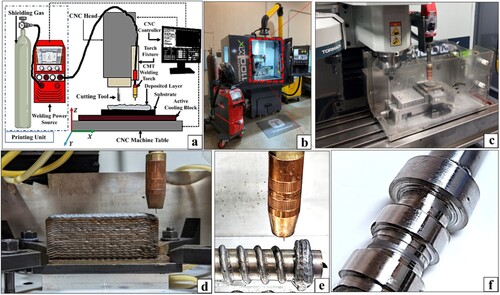
Cold metal transfer (CMT) wire-arc directed energy deposition (WA-DED) was used to fabricate M250 structures – the design schematic and physical apparatus are displayed in (a,b), respectively. A heat exchanger for active cooling was designed and manufactured in-house and installed between the substrate and the CNC machine table ((c)). The heat exchanger consists of a network of coolant passages directing a continuous stream of coolant back and forth underneath a thin plate before exiting to a storage tank. The dimensions of the heat exchanger correspond to those of the substrate. Coolant temperature was maintained at ∼21°C. The hybrid WA-DED system comprises a 4-axis CNC milling machine (Tormach Inc.) and a CMT welding power source (Fronius International GmbH). The CMT welding torch was mounted perpendicular to the XY plane on the Z-axis. The supplementary table (ST1) represents the chemical composition of grade 250 maraging steel wire (TURBALOY® 250) with a nominal diameter of 0.030 in. (∼0.8 mm) used as the filler material for fabricating the 3D structures. TURBALOY® 250, an ultra-high-strength martensitic steel, was used as the feedstock based on extensive application in hydrospace, aeronautics, aerospace, and tool manufacturing [Citation36]. The monolithic walls ((d)) were deposed on a mild steel substrate 180 mm long, 75 mm wide, and 12.5 mm thick. Before deposition, the mill scale was removed from the substrate, and the surface was thoroughly cleaned using ethanol. Radial bimetallic structures were deposited on SS304L rod substrate, as displayed in (e,f).
Figure 1. Experimental setup. (a) Schematic representation; (b) The hybrid WA-DED setup illustrating the coupling of CMT welder and CNC; (c) Welding torch showing deposition on the CNC table; (d) Multilayer M250 wall structure; (e) Welding torch showing deposition on the rotating 4th axis; (f) Finished radial bimetallic with SS304L core and maraging 250 shells.
Multiple monolithic M250 slabs were produced with the same build parameters, measuring approximately 110 mm high, 130 mm long, and 23 mm thick. A visual representation of the hybrid WA-DED processing of the M250 wall is depicted in supplementary Figure S1. An interlayer dwell pause was used to mitigate the impact of consecutive thermal cycles on the microstructure of preceding deposited layers. The exact time interval for the pause varied, governed by the time required for the deposited layer to cool below 165°C as outlined in the AWS 2005 Handbook [Citation37]. Arc length stabilisation and pulse/dynamic correction for bead deposition were utilised.
2.2. Radial bimetallic deposition
Radial bimetallic structures of stainless steel 304L (SS304L) and M250 were also produced on the same equipment as the monolithic structures but used an additional rotary 4th axis on the CNC mill to hold and rotate a solid SS304L 25.4 mm diameter rod substrate. The CMT torch was kept perpendicular to the rod during deposition. The rotational speed of the spindle was 50 mm/min, with deposition parameters identical to those used for monolithic deposition.
2.3. Bead geometry optimisation
Parameters were categorised as fixed and variable and presented in supplementary Tables ST2 and ST3. Fixed and variable parameters were experimentally optimised (Figure S2a, b) based on the average bead width and height. Individual beads were cut longitudinally to promote bead width, penetration depth, and height measurement, with the optimal bead measuring 4.9, 3.2, and 0.9 mm, respectively (Figure S2c). The final fixed process parameters used for the deposition of the optimum M250 WA-DED single beads are shown in Table ST2.
For the establishment of optimal variable parameters, beads with high reinforcement height and low penetration depth were targeted, where the width of the bead is nearly equal to the summation of the penetration depth and reinforcement height (r > p, w≈r + p, Figure S2c) [Citation38]. Heat input (J/mm) was calculated using the formula below [Citation39].
The welding efficiency (η) for CMT-based GMAW was assumed to be 0.8. The variables used in the formula are V for arc voltage in volts, I for average current in amperes, and S for torch speed in millimeters per minute. Variable parameters for deposition were finalised with an arc voltage of 17 V, an average arc current of 65 A, and a wire feed rate of 8 m/min. The heat input for this optimal set of parameters was calculated to be 133 J/mm (Table ST4).
2.4. 2D X-ray image analysis, characterisation, and testing
The as-deposited monolithic wall specimens were subjected to X-ray computed tomography (XCT) analysis, but only 2D X-ray imaging was performed because the sample's geometry prevented CT imaging. Penetration by X-rays was difficult due to nickel and iron content and specimen length-to-width ratio [Citation40]. Imaging was performed sequentially from top left to bottom right on a Nikon XT H225 XCT machine at 225 kV and 191µA. The representative X-ray image was affected by the location of the sample to the X-ray target and was geometrically scaled smaller or larger based on the sample's position [Citation41].
Monolithic samples for microstructural analysis were extracted longitudinally from the top, middle, and bottom sections. As-processed and heat-treated samples were ground using SiC sandpapers of 80–2000 grit sizes, followed by polishing with a suspension of 1–0.05 μm Al2O3/DI water for 15 min each. Ultrasonic cleaning with ethanol followed for at least 30 min. The samples were analyzed using a Rigaku mini flex 600 X-ray Diffractometer, which was equipped with a 2-D General Area Diffraction Detector (GADDS) mounted on a theta-theta goniometer and scanned using Cu k-alpha radiation (1.54 Å at 40 kV and 20 mA) at a speed of 5° per minute over the range of 20° to 100° 2θ. The raw data obtained was processed using Rigaku PDXL software. Samples were etched by submerging them in a mixture of 10 ml HNO3, 15 ml HCl, 10 ml CH3COOH, and 2–5 drops of glycerol for 30–45s [Citation42]. The etched metallographic samples were analyzed using a digital optical microscope (Keyence VHX 7000 series). The SS304L-M250 radial bimetallic structures were similarly prepared and analyzed after sectioning along the longitudinal and lateral directions with subsequent grinding and polishing. Crystallographic phase orientation was determined by EBSD analysis. A scanning electron microscope (Sirion SEM) and an EDAX Velocity system were used. An accelerating voltage of 15 keV was used with a stage tilt of 70°, 2 µm step size, and 15 mm working distance. The data was analyzed with TSL OIM software using a 0.1 confidence index. Data at lower confidence index values was discarded. Neighbour orientation correlation cleanup was done at a minimum confidence index of 0 and a cleanup level of 3.
The Vickers hardness profiles were obtained using a Phase II Plus Micro Vickers hardness tester (Upper Saddle River, NJ, USA) with a 1.96 N load (HV0.2) for 15s dwell time. 50–60 indents were made in each zone from top-to-bottom. Tensile specimens were extracted from the monolithic walls via commercial wire EDM services, then cut by waterjet to form miniaturised tensile dogbones based on the ISO/ASTM 52909-E8/E8M standard. These specimens had a 6 mm gauge length, 4 mm width, and 1 mm thickness. They were evaluated on a Shimadzu AGS-X 50kN autograph universal testing machine (source) at 1 mm/min crosshead speed and room temperature. Charpy impact specimens were prepared per ASTM E23-18 and fractured using an impact testing machine (American Machine and Metals, Inc., Riehle testing machine division).
Heat treatment of selected samples was performed as recommended by the ASM handbook for maraging steel, 250-grade [Citation43]. Solutionizing occurred at 815°C for 1 h per inch of thickness, followed by air-cooling to room temperature. Aging followed at 480°C for 3 h before air-cooling to room temperature (supplementary Figure S3).
3. Results
3.1. 2D X-ray imaging for defect detection
Three CMT WA-DED depositions of M250 in monolithic slab form were produced. Several defects were observed on the outer surface of the deposited wall, primarily appearing at the border between two consecutive layers. Each layer is approximately 3 mm thick ((a)). The visible defects can be identified as porosities or pits (open defects), forming when gas cavities inside the weld metal solidify after the gas escapes from the bead's surface [Citation44]. 2D X-ray imaging showed internal defects as white spots ((b)). The internal defects were measured and analyzed using GIMP, an open-source image processing software, and less than 2% had a size greater than 300 μm. The total defect area was calculated to be less than 5% of the build volume using the same image processing software.
Figure 2. Wire-arc directed energy deposition (WA-DED) produced slab for analysis. (a) Front view of the M250 slab, asterisks displaying outer defects and crosshairs displaying quadrants for 2D X-ray imaging, (b) 2D X-ray images of the WA-DED M250 quadrants, asterisks displaying internal defects, and interlayer contrast. (c) X-ray diffractograms of the bottom (B), middle (M), and top (T) sections from the as-printed specimen with scanning direction along the build direction (z-axis). The c inset focuses on the austenite (γ) (020) peak at 2θ = 50.75 and the martensite (θ) (020) peak at 2θ = 64.9 for the bottom and top XRD spectra], (d) side view of the M250 slab displaying different sections and the sample cut from the slab for XRD analysis, (e) X-ray diffractograms of the bottom (B), middle (M), and top (T) sections from the heat-treated specimen with scanning direction along the build direction which is also the z-axis.
![Figure 2. Wire-arc directed energy deposition (WA-DED) produced slab for analysis. (a) Front view of the M250 slab, asterisks displaying outer defects and crosshairs displaying quadrants for 2D X-ray imaging, (b) 2D X-ray images of the WA-DED M250 quadrants, asterisks displaying internal defects, and interlayer contrast. (c) X-ray diffractograms of the bottom (B), middle (M), and top (T) sections from the as-printed specimen with scanning direction along the build direction (z-axis). The Figure 1c inset focuses on the austenite (γ) (020) peak at 2θ = 50.75 and the martensite (θ) (020) peak at 2θ = 64.9 for the bottom and top XRD spectra], (d) side view of the M250 slab displaying different sections and the sample cut from the slab for XRD analysis, (e) X-ray diffractograms of the bottom (B), middle (M), and top (T) sections from the heat-treated specimen with scanning direction along the build direction which is also the z-axis.](/cms/asset/4d44de73-cc42-476c-8244-421f28a067a3/nvpp_a_2296127_f0002_oc.jpg)
3.2. Phase analysis
X-ray diffraction was done on the WA-DED samples to identify phases. Areas of measurement included the bottom (B), middle (M), and top (T) regions along the build direction, as shown in (c–e). For comparison, X-ray diffractogram results were also obtained for samples in as-processed and heat-treated conditions ((c,e). The as-processed samples primarily consist of martensite (θ) peaks with trace amounts of austenite (γ) peaks in the bottom site of the sample, as observed in (c) inset, as per Joint Committee on Powder Diffraction Standards (JCPDS) pattern 96-411-3942 and 96-901-4712, respectively. The as-processed samples displayed a preferred crystallographic orientation along the (011) plane of the martensitic phase at 2θ of 44.62°, 44.6°, and 44.59° in the bottom, middle, and top zone, respectively, while trace amounts of the austenitic phase showed a preferred orientation along the (020) plane at 2θ of 50.88°, 50.87°, and 50.74° in the bottom, middle, and top zone, respectively. The austenitic phase fraction is calculated to be 1.12%, 1.08%, and 1.0% in the as-processed sample's bottom, middle, and top zones, respectively.
After heat treatment, the M250 samples exhibited an increase in the peaks of the austenitic phase ((e)). The heat-treated samples showed a preferred orientation along the (011) plane of the martensitic phase at 2θ of 44.59°, 44.55°, and 44.59° in the bottom, middle, and top zone, respectively, while the austenitic phase showed a preferred orientation along the (111) plane at 2θ of 43.53°, 50.48°, and 50.47° in the bottom, middle, and top zone, respectively. This also coincides with the relevant JCPDS patterns. In the heat-treated sample's bottom, middle, and top zone, the austenitic phase fraction is calculated to be 19.7%, 17.7%, and 15.4%, respectively, which correlates with results seen by other researchers [Citation45].
3.3. Microstructural characterisation
Samples were extracted from the M250 wall structure for macro- and microstructural analysis of the bottom, middle, and top zones ((a)). Stereoscope images of the as-processed etched M250 samples from the top, middle, and bottom zones were also obtained ((b–d)). These images show complete fusion between distinct weld layers without noticeable defects. The remelting boundaries are visible in (b1–d1).
Figure 3. As-processed microstructure. (a) Side view of the M250 wall showing different sections and the sample cut from the wall for microstructural analysis; (b, b1, b2, b3) Microstructure in the top section of the M250 wall at different magnifications; (c, c1, c2, c3) Microstructure in the middle section of the M250 wall at different magnifications; (d, d1, d2, d3) Microstructure in the bottom section of the M250 wall at different magnifications.
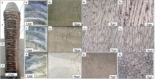
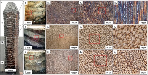
In the as-processed samples, distinct features were observed throughout the material: long dendritic grains in the upper zone, coarse columnar grains in the middle zone, and a fine cellular microstructure in the lower zone. Conversely, the heat-treated samples exhibited a dendritic top zone, a lathy middle zone, and a cellular bottom zone characterised by discrete austenitic fine equiaxed grains ().
Figure 4. Heat-treated microstructure. (a) Side view of the M250 wall showing different sections and locations of the sample extracted from the wall for microstructural analysis; (b, b1, b2, b3) Microstructure in the top section of the M250 wall at different magnifications; (c, c1, c2, c3) Microstructure in the middle section of the M250 wall at different magnifications; (d, d1, d2, d3) Microstructure of the bottom section of the M250 wall at different magnifications.
3.4. Electron backscattered diffraction (EBSD
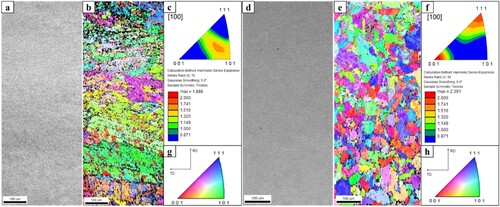
Inverse pole figure maps for as-processed and heat-treated specimens were obtained through EBSD evaluation to characterise the microstructure and crystallographic texture (). For as-processed specimens sectioned perpendicular to the build plane with poles aligned normally to the section plane, the crystallographic orientation is concentrated around the {101} plane aligned with the rolling direction (RD). In similarly sectioned specimens subjected to heat treatment, the same orientations are not seen, with a near absence of {101} plane alignment. Columnar grains oriented perpendicular to the build plane are evident in both cases, although the heat-treated texture shows homogeneous grain formation. The reference direction (build direction) is shown in the crystallographic coordinate frame, plotted as inverse pole figures showing a misalignment from the anticipated {100} texture that would be expected along the build direction.
Figure 5. EBSD comparison of as-processed and heat-treated microstructure and crystallographic texture; (a) SEM image of the as-processed specimen; (b) EBSD grain orientation map of as-processed specimen; (c) Inverse pole figure of as-processed specimen; (d) SEM image of heat-treated specimen; (e) EBSD grain orientation map of heat-treated specimen; (f) Inverse pole figure of heat-treated specimen; (g) Ferrite orientation and color key for as-processed EBSD grain orientation map; (h) Ferrite orientation and color key for heat-treated EBSD grain orientation map.
3.5. Microhardness
The as-processed M250 sample displayed a non-uniform variation in the average hardness from the top to the bottom zone. The average microhardness value of the as-processed sample was calculated to be 318 ± 4 HV0.2, 344 ± 3.5 HV0.2, and 378 ± 3 HV0.2 at the top, middle, and bottom, respectively. These hardness values effectively showed a 19% increase moving from the top to the bottom of the as-processed sample. Predictably, the heat-treated sample showed a more uniform microhardness throughout the structure. The average microhardness value for the heat-treated samples was calculated to be 478 ± 5 HV0.2, almost 26% more than that of the as-processed sample.
3.6. Mechanical properties
The yield strength (0.2% YS) and ultimate tensile strength (UTS) of the M250 samples in as-processed and heat-treated conditions were obtained, with the loading direction parallel as well as perpendicular to the build direction (). The samples loaded parallel to the build direction are further classified into Group A from the beginning side of the deposition and Group B from the terminal end of the deposition. Similarly, the samples loaded perpendicular to the build direction are further classified into Group C from the top zone and Group D from the bottom zone. Tensile properties are therefore calculated based on six samples (n = 6) from each orientation. Specimens containing obvious volumetric defects in their gauge length are excluded, as this type of defect invalidates results by introducing stress concentrations, non-uniform deformation, and material instability.
Table 1. Yield strength (YS) and ultimate tensile strength (UTS) of as-processed and heat-treated M250 samples in different orientations.
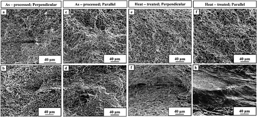
The as-processed samples demonstrated superior (UTS) and 0.2% YS compared to the conventional counterparts, regardless of the orientation [Citation46]. Notably, samples loaded parallel to the build direction exhibited isotropic behaviour, while samples loaded perpendicular to the build direction exhibited anisotropic properties. The fracture morphology of the four as-processed samples relative to their unique orientations is characterised by dimples and microvoids ((a–d)). The fracture morphology of the four heat-treated samples relative to their unique orientations are displayed in (e–h). The fracture morphologies of the heat-treated samples loaded perpendicular to the build direction revealed a quasi-cleavage fracture, distinctly differing from the as-processed samples ((g,h)).
Figure 6. As processed tensile results. (a, b) SEM micrograph of the fracture surface of as-processed M250 tensile specimens perpendicular to the build plane showing deep dimples and no cleavage planes; (c, d ) SEM micrograph of the fracture surface of as-processed M250 tensile specimen parallel to the build plane, showing dimples. (e, f) SEM micrograph of the fracture surface of heat-treated M250 tensile specimens perpendicular to the build plane, showing deep dimples and no cleavage planes; (g, h) SEM micrograph of the fracture surface of heat-treated M250 tensile specimen parallel to the build plane, showing cleavage planes along with some dimples.
3.7. Impact toughness
Charpy impact tests were carried out for the samples to evaluate toughness as a function of strength and ductility, indicative of the material's ability to absorb energy before failure. Specimens were prepared parallel and perpendicular to the build-plane in as-processed and heat-treated conditions; their respective fracture surfaces are displayed in Figures a, b, c, and d with measured impact energy displayed in (e). The as-processed M250 samples displayed impact toughness of approximately 50 ± 2J in the perpendicular orientation and 46 ± 6J oriented parallel to the build plane. The heat-treated M250 samples in both orientations showed reduced impact toughness value. These samples show an impact toughness of approximately 33 ± 5 J in the perpendicular direction and 25 ± 1.5 J in the parallel direction to the build plane. As-processed samples displayed higher values than the heat-treated counterparts regardless of orientation, although samples oriented perpendicular to the build plane did register higher toughness values compared to samples oriented parallel to the build plane in both states.
Figure 7. Charpy impact test results for M250 samples in different orientations and treatment manufactured via hybrid WA-DED; (a, a1) Optical and SEM micrograph of the fracture surface of as-processed M250 Charpy specimens parallel to the build plane showing deep dimples and no cleavage with an impact energy of 46 ± 6J; (b, b1) Optical and SEM micrograph of the fracture surface of as-processed M250 Charpy specimens perpendicular to the build plane showing deep dimples and no cleavage with an impact energy of 50 ± 2J; (c, c1) Optical and SEM micrograph of the fracture surface of heat-treated M250 Charpy specimens parallel to the build plane showing no dimples and cleavage planes with an impact energy of 25 ± 1.5J; (d, d1) Optical and SEM micrograph of the fracture surface of heat-treated M250 Charpy specimens perpendicular to the build plane showing cleavage planes with an impact energy of 33± J; (e) Summarised impact energy for the varying samples.
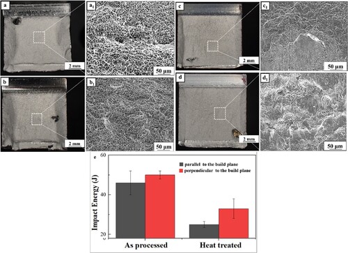
Stereoscopic images of the fracture surfaces for the as-processed samples were obtained, comparing specimens oriented parallel and perpendicular to the build plane ((a,b)). A shear lip and the fibrous zone are visible, indicating a slow crack growth rate and good toughness. The fracture morphologies of these samples are characterised by numerous deformed dimples of various sizes, indicating transgranular ductile fracture ((a1,b1)). Stereoscopic images of fractured heat-treated specimens were also obtained, with fracture morphologies found to contain flat facets and cleavage planes, indicating quasi-cleavage brittle fracture ((c1,d1)).
4. Discussion
The present research was concerned heavily with AM deposition and analysis of M250 in as-processed and heat-treated conditions. For a complete characterisation of M250 in WA-DED form, monolithic slab M250 structures were produced after optimised process parameters for the CMT process were identified. Defects were analyzed from 2D X-ray attained images, and mechanical and microstructural analysis samples were partitioned in various orientations. A heat treatment was implemented for comparison. Crystallographic phase, microstructure, microhardness, tensile, and Charpy impact toughness were all investigated and compared between specimen orientations throughout the monolithic slabs. EBSD analysis revealed the as-process and heat-treated sample texturing. The comprehensive analysis in the current study allowed for a critical understanding of M250 produced using WA-DED, enabling the fabrication of proof-of-concept bimetallic structures. An application-based splined shaft, auger, and concentric shaft lobe were fabricated using a radial deposition strategy to combine M250 and SS304L. These bimetallic structures were sectioned for microstructural, microhardness, and metallurgical interface evaluation. Investigation of M250-based bimetallics promotes the use of WA-DED for advanced maraging steel structures. The combination of AM maraging steel with secondary materials holds significant potential for enhanced performance in an expanded design space. The study's representative radially bimetallic specimens are a valuable foundation for further exploration of material coupling and designs.
4.1. Internal defects
With larger structures, challenges in maintaining proper arc control, melt pool geometry, and thermal control increase. These challenges raise the possibility of internal defects in the upper layers. The observed internal porosities of the produced M250 WA-DED slabs displayed characteristics of blow-hole defects, which can occur when gas cavities remain within a bead. Numerous factors, such as uneven surfaces, contamination, and insufficient shielding, aid in forming these defects [Citation5]. Maintaining a uniform surface becomes challenging with progressive layers, which is why hybrid manufacturing has been adopted for large industrial-scale WA-DED-produced structures. Although the CMT-based AM process can substantially reduce variation of the top surface, 2D X-ray image analysis revealed the presence of internal porosity.
4.2. Phase analysis
The X-ray diffractogram (XRD) analysis of the as-processed M250 revealed a dominant martensite (θ) phase, accompanied by a trace presence of retained austenite (γ), as was revealed when further analyzing the XRD spectra and focusing on the austenite (020) martensite (020). In contrast, the diffractogram pattern of the heat-treated samples displayed a higher proportion of austenite peaks when compared to the as-processed sample. The variation of austenite revealed an increasing trend from top-to-bottom in both as-processed and heat-treated samples. The micro-segregation of solute particles at cellular boundaries during solidification may account for a trace presence of austenitic phase [Citation10]; this kind of austenite is termed retained austenite and forms during metal solidification from the austenitizing temperature [Citation47]. The rapid cooling rate and the successive thermal cycle at the bottom zone are the reasons for the higher austenitic content compared to the middle and top zones of the as-processed M250 samples [Citation45].
The increase in the formation of the austenite phase fraction in the heat-treated samples may have occurred due to the reversion of the martensite to austenite in the retained austenite region [Citation10] or because of the disintegration of the Ni3Ti Phase [Citation48]. Considering these austenite phase fractions are formed primarily during the aging process of the heat treatment by the diffusion-controlled reaction [Citation10], these are termed reverted austenite. Hence, heat treatment (solutionizing + aging) results in the transformation of martensite to austenite. Similar research findings have been reported by Kempen, et al. [Citation49]. It is also noticeable from the XRD spectra in (e) that under heat-treated conditions, there are no peaks of intermetallic compounds. This can be attributed to the low phase content, which may be less than 5% [Citation50], and the widely dispersed distribution [Citation51].
4.3. Microstructural characterisation
The remelting boundaries visible in (b1–d1), indicate the partial remelting and repeated reheating during the WA-DED process. With progression into the production of the M250 wall, remelting of previously deposited layers at a specific thickness occurred. Thus, the newly melted wire material and the partially melted previous layer formed a molten pool. The melting, remelting, and scanning strategy-dependent thermal gradient showed the observable microstructure contrast.
The as-processed samples displayed distinct microstructures from top-to-bottom, as depicted in (b2–d2). The topmost site of the as-processed M250 sample exhibited a typical dendritic structure, which displayed a reduction in contrast after etching owing to the low amount of austenite ((b3)). This top region microstructure resulted from the molten pool's direct solidification without subsequent layer remelting [Citation52]. As shown in (c3), columnar grains were predominantly present in the middle region. The slight tilt in the grains in the middle zone was due to the type of deposition path selected, which enables the grains to grow in the direction of the fastest heat dissipation. Compared to the top region, the middle region had more austenite content. The bottom zone's microstructure was dominated by fine cellular grains due to rapid cooling, as illustrated in (d3). The bottom zone was also subjected to a higher thermal load due to a high cumulative number of thermal cycles; therefore, it aged more than the top and middle zones. This partial aging effect was the leading cause of higher austenitic content at the bottom than in the middle and top zones for the as-processed sample.
The microstructure variations among the three regions in the as-processed M250 wall structure (top, middle, and bottom) were influenced by partial remelting and thermal cycling resulting from the layer-by-layer deposition process. The thermal gradient encourages grain growth along the build direction, permitting dendrites to transform into high-aspect ratio columnar grains. The direction of dendritic growth is affected by the heat flow in the WA-DED process, which is largely from the top layer to the bottom. The temperature gradient of the solidifying liquid and the solute's increased concentrations at the liquid–solid interface both influence the direction of growth [Citation26]. Considering thermal dissipation is greatest with the initial layer deposition during the WA-DED process, equiaxed grains were observed. Dendrite growth perpendicular to the scanning strategy was observed with the latter layer depositions. Additionally, remelting resulted in element segregation within the sample – particularly with Nickel – leading to the development of austenite [Citation53,Citation54].
(a) displays the side view of the 3D-printed M250 wall structure, with the bottom, middle, and top zones marked for macro and microstructure analysis. (b–d) present optical stereoscope images of heat-treated etched samples from the top, middle, and bottom zones, respectively, which exhibit distinct weld layers with no defects. The high contrast of these heat-treated samples after etching indicates higher austenite formation. The remelting boundaries are visible in (b1–d1) indicate partial remelting and reheating of the previous layer during the additive deposition of a new layer. As shown in Figs, a clear distinction has been observed in the heat-treated microstructure from top-to-bottom. 4b2, c2, and d2, respectively. In the top zone of the heat-treated sample, the microstructure exhibits distinct austenitic regions along the boundaries between dendrites, as depicted in (b3). After heat treatment, moving down from the top zone towards the middle and bottom zone ((c3,d3)), the low-carbon lath martensite refines, the austenitic phase grain aspect ratio reduces, and the needle-like microstructure evolves to an equiaxed grain profile [Citation26].
The austenite area was observed when the samples were heated at 815°C for 1 h per inch, cooled to room temperature, and then kept at 480°C for 3 h. This might be because the previous solution treatment was insufficient, resulting in unstable martensite formation after cooling to room temperature. Consequently, with the increase in temperature, the martensite portion underwent a recovery process and transformed into austenite, known as reverted austenite [Citation52]. Austenite forms when the M250 steel is heated at 650°C or higher [Citation55]. When the WA-DED-based structure is aged at only 480°C, more austenite forms than the as-deposited condition (shown in (b3–d3)). This suggests that elemental segregation and grain refinement influence the austenite reversion temperature.
Considering M250 steel is age-hardened, the material's strength is derived directly from solutionizing and aging during heat treatment. During heat treatment, grain size would be expected to become more refined as the martensite phase decomposes into a mixture of martensite and austenite, accompanied by the formation of strength-inducing intermetallic compounds. To some extent, this behaviour is seen in ; distinct bands of crystal growth alignment are seen in the as-processed material, indicative of cyclical heating, then disappear after heat treatment. Equiaxed grain formation is seen in the heat-treated specimen, along with the development of small dispersed boundary grains. Also noticeable is a shift in crystallographic orientation that occurs during heat treatment. Although both conditions exhibit weak textures overall, the as-deposited material appears to have periodic strata of moderate texture alignment, with crystals trending toward a single preferred orientation on each layer. This orientation observation is not consistent between the two states. After heat treatment, preferential crystallographic orientation was reduced, with crystals shifting away from and losing textured alignment with the {101} plane. Alignment became more familiar with the {111} and {001} planes. When considered together with grain formation, these observations suggest that a complete recrystallization has occurred, with nucleation and growth of entirely new grains along more widespread orientations as heat-treated material undergoes a more consistent thermal exposure. Complete recrystallization would help explain changes to mechanical properties such as tensile, toughness, and fracture behaviour. The increase in varying crystal orientations of new grains coincides with a heating and cooling profile experienced during heat treatment that is more uniform than repeated thermal cycling during layer-by-layer deposits.
4.4. Microhardness
The microhardness of the as-processed sample exhibited a notable variation along the build direction, ranging from top-to-bottom. The hardness values were 318 ± 4HV0.2, 344 ± 3.5HV0.2, and 378 ± 3HV0.2, taken at the sample's top, middle, and bottom, accounting for a 19% increase in hardness. In contrast, the heat-treated sample displayed a more uniform hardness profile, with an average microhardness value of 478 ± 5HV0.2; this equates to a 26% increase in hardness over the as-processed sample. One explanation for the hardness variation of the as-processed sample is the layer-by-layer fabrication process. The repeated thermal cycling and heat accumulation led to a transient in-situ heat treatment, resulting in microstructural transformations and intermetallic precipitates. The quantity of precipitates will vary along the building direction; upper layers experience less thermal cycling and, therefore, less precipitation formation. Xu, Xiangfang, et al. reported similar results, ranging from 44 to 49 HRC from top-to-bottom [Citation26]. The quantity of the precipitates is directly proportional to the number of thermal cycles, so the number of precipitates will be maximum at the bottom zone, leading to a higher hardness than the top. Due to the active cooling setup used during deposition, the initial layers at the bottom zone show a rapid solidification rate, resulting in the formation of finer grains, which is a primary reason for the higher hardness observed in these layers. This effect has been previously reported [Citation39] and is often described using the Hall-Petch equation shown below, which relates grain size to mechanical properties.
where σ is the yield or flow stress at a particular plastic strain,
and
are constants that depend on the material, and d is the mean grain size. As per the Hall-Petch equation, smaller grain sizes increase strengthening [Citation56,Citation57].
The increase in microhardness for the heat-treated sample can be attributed to precipitation hardening during aging. The solutionizing step of the heat treatment cycle for the M250 dissolved the alloying elements, homogenising the microstructure, resulting in uniform distribution of the alloying elements. When the solutionized M250 was further heated at 480°C for 3 h, the alloying elements precipitated out of the solution to form a uniform distribution of fine intermetallic particles throughout the build direction from top to bottom. These precipitates function as obstacles to the movement of the dislocations and enhance the strength. Studies have reported a similar trend where maraging steels were subjected to heat treatment methods, such as quenching and aging at 400°C–500°C for two to six hours [Citation58]. Varying aging times and higher temperatures have been widely assessed in precipitation kinetics research [Citation58], resulting in a 10% increase in hardness for solutionized and quenched maraging steels after aging for 30s at 200°C [Citation58].
4.5. Mechanical properties
The ultimate tensile strength (UTS) and the 0.2% offset yield strength (0.2% YS) of the as-processed samples A and B displayed values ranging from 1184 ± 47 MPa to 1080 ± 47 MPa and from 1147 ± 56 MPa to 1075 ± 54 MPa, respectively. The UTS and the YS values in orientations A and B do not vary much, indicating isotropy where the loading direction is parallel to the build direction. The UTS and the 0.2% YS of the as-processed samples C and D displayed values ranging from 1202 ± 51 MPa to 1090 ± 30 MPa and from 1217 ± 13 MPa to 1140 ± 11 MPa, respectively, which indicates anisotropy in the tensile strength where the loading direction is perpendicular to the build direction. The observed anisotropy in tensile strength between samples C and D was likely due to the microstructural heterogeneity and the uneven distribution of austenite (γ) from the top-to-bottom of the as-processed wall structure. This observation was validated by the XRD results ((c) inset) and microstructural imaging ((d3,b3)) along the build direction. The XRD data revealed a trace presence of austenite (γ) at the bottom and its reduction at the top of the as-processed structure. The microstructure imaging also revealed a change in the observed microstructure along the build direction for the as-processed sample. From (b3–d3), the equiaxed grains evolved into high aspect-ratio needle-like grains. When considering the XRD results and microstructure evolution along the build direction for the as-process sample, the analysis of these results corroborates with the observed microhardness variation and differing values for the ultimate tensile strength (UTS) for samples C and D.
The UTS and 0.2% offset yield strength (0.2% YS) of the as-processed samples in both horizontal and vertical orientations exhibited comparable, or in some cases, even superior properties than those of conventionally manufactured wrought and unaged M250 steel [Citation46]. In line with these findings, a study by Suryawanshi et al. reported comparable results, citing the analogous effective slip length of maraging steel 300 produced using the selective laser melting (SLM) method, along with the insignificant effects of solid solution strengthening as a possible reason for the comparable properties observed [Citation59]. However, as shown in , the UTS and the YS of the samples fabricated perpendicular to the build plane displayed a 4% and 3.5% reduction in value to those fabricated parallel to the build plane. The reduction in strength in the samples fabricated perpendicular to the build plane can be attributed to the presence of layer bands throughout the build direction [Citation26]. Due to their interlayer bonding, layer bands can lead to elevated stress concentration in samples fabricated perpendicular to the build plane. Consequently, the strength of these samples tends to reduce when compared to samples fabricated parallel to the build plane [Citation60].
Certain microvoids can be expected to be derived from pre-existing defects, which serve as stress concentration sites prompting crack initiation during tensile testing [Citation61]. The presence of particle-like structures within the larger dimples suggests that this occurred, indicating that the samples experienced the formation, expansion, and joining of micro-cavities along with crack initiation and propagation; this type of failure is known as transgranular ductile fracture.
The UTS and the 0.2% YS of the heat-treated samples revealed a noticeable increase in the value as compared to the as-processed M250 samples. Referring to , the UTS and the 0.2% YS of the heat-treated samples, where the loading direction was parallel to the build direction, displayed an increase of almost 32%. The same trend was observed in the heat-treated samples, where the loading direction is perpendicular to the build direction, with an increase of almost 28% compared to as-processed counterparts. Higher strength and isotropic properties of the heat-treated M250 samples are attributed to the formation and uniform distribution of Ni3(Mo, Ti) and Fe2Mo precipitates. The presence of precipitated particles and their associated stress fields effectively impede dislocation movement, resulting in material strengthening. This phenomenon is anticipated to reduce plastic strain within the material, consistent with results obtained by Casati et al. [Citation48].
In heat-treated specimens, the treatment process allows for the formation of precipitates, which inhibits the movement of dislocation. As a result, when the dislocation density reaches a sufficient threshold, cleavage fracture is promoted through microcracking along specific crystallographic facets [Citation59]. The fracture patterns depicted in (g,h) align with this mechanism. Additionally, the reduced ductility of the heat-treated M250 samples may be attributed to the combination of the natural aging phenomenon that occurs during the melting and remelting of each layer in the WA-DED process and furnace aging after the sample preparation. This phenomenon can be regarded as the underlying cause for the higher formation of precipitates compared to the as-processed samples, resulting in reduced ductility. Yasa et al. demonstrated that nitrogen and oxygen absorption during the melting and solidification stages could contribute to the lower ductility reported in after-aging SLM samples [Citation62].
As stated in the ASTM standard, the heat-treated sample's UTS and 0.2% offset yield strengthen horizontal and vertical orientations exhibit inferior properties compared to conventionally manufactured wrought heat-treated M250 steel [Citation63]. On average, the WA-DED-based heat-treated samples displayed an 11% and 19% decrease in UTS and 0.2% YS compared to the wrought heat-treated M250 samples. One cause for the decline in strength can be attributed to a suboptimal aging response [Citation26]. The aging response of a component is strongly influenced by its microstructural condition. WA-DED-based M250's grain boundaries differ significantly from those of wrought M250, lacking initial compositional homogeneity. WA-DED samples exhibit needle-like grains, low-angle grain boundaries, and thermal induced strain. The wrought M250 has equiaxed grains with high-angle grain boundaries. Cold strain between the deposited layers may induce recrystallization, which helps form a structure characterised by high-angle grain boundaries and could be a potential solution for this issue [Citation26]. However, more rigorous experiments should be conducted to optimise the heat treatment process for the samples fabricated via the WA-DED process.
The Charpy impact specimens perpendicular to the build plane displayed improved impact toughness compared to the parallel-to-the-build plane specimens in the as-processed condition; the anisotropy is attributed to the interlayer slip. When subjecting the specimen perpendicular to the build plane to impact testing, a portion of the energy is absorbed through interlayer slip. The interlayer acts as a macro slip band, producing a higher impact energy requirement for fracturing the specimen [Citation60].
The observed results exhibit apparent anisotropy due to the layered nature resulting from the layer-by-layer deposition in the WA-DED process. The impact toughness of the heat-treated M250 sample exhibited a 34% reduction in the perpendicular direction to the build plane, while the sample in parallel to the build plane displayed a 45% reduction compared to their respective as-processed counterparts. The decrease in impact toughness can be attributed to the formation of the precipitated intermetallic particles after the heat treatment [Citation61]. Twin formation as a lath martensite substructure in heat-treated M250 specimens may also factor in [Citation60]. (c,d) display the optical stereoscopic images of the fracture surfaces for the samples parallel and perpendicular to the build plane in heat-treated conditions. These figures reveal a large radical zone without observable shear lip and the fibrous zone, indicating a fast crack growth rate and diminished toughness.
4.6. Bimetallic structure
With monolithic M250 microstructure, crystallographic phase presence, mechanical properties, and heat treatment response analysis completed and thoroughly understood, three representative radial bimetallic structures composed of M250 and SS304L were next produced. A concentric lobe shaft ((f)), a splined gear-like shaft ((a)), and a helical auger-like structure ((b)) were manufactured using the rotary 4th axis of the CNC machine (, and ). These depositions demonstrate the producibility of complex near-net radial bimetallic products as a natural outgrowth of monolithic capability. Bimetallic structures offer many functional advantages over single-material compositions, with added potential in the combination of material properties, cost-effectiveness, flexibility in the distribution of location-specific properties, enhanced mechanical or metallurgical bonding, and in-situ alloying [Citation64]. In the radial context, unique geometric relationships add design freedom to enable structures with new mechanical capabilities and strategic material usage.
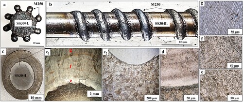
Figure 8. Bimetallic structure characterisation. (a) Section view of a representative splined shaft structure fabricated using WA-DED with an SS304L centre rod and M250 splines; (b) Plan view of a representative auger screw structure fabricated using WA-DED on an SS304L centre rod to form an M250 helix; (c) section view of a radial bimetallic disc structure produced via WA-DED; (c1, c2) Low magnification optical image of the SS304L –M250 bimetallic disc structure showing the interaction between M250 and SS304L, including the heat affected zone; (d) High magnification optical image of the interface between SS304L and M250 showing uniform mixing; (e–g) M250 microstructure taken from the build.
Destructive inspection of the conceptual demonstration articles exposed no internal flaws or defects, and microscopy confirmed the presence of anticipated microstructural formations and hardness variations. An auger screw was fabricated by continuing the deposition process of M250 onto an SS304L core. Similarly, the radial bimetallic configuration can find application in the automotive sector for producing camshafts, incorporating a cost-effective core with a mechanically superior casing for the lobe structure. The radial bimetallic approach presented here demonstrates potential applicability in on-site repair sectors, precisely the splined shaft concept featuring M250 splines and an SS304L core. The presented proof-of-concept application-based structures can be projected to diverse service applications providing site-specific properties or performance. Such material coupling opens the door for innovative solutions and optimised performance in various industries.
(c) illustrates the lateral cross-section of the radial bimetallic structure manufactured by the hybrid wire-arc directed energy deposition (WA-DED) setup shown in (b). Observable from the optical stereoscopic image in (c), the SS304L core and the M250 shell/casing are distinctly visible. No defects were observed in the M250 casing, either at the interface between SS304L and the first layer or between subsequent layers of the M250.
Five radial layers of M250 were deposited on the SS304L rod substrate, resulting in a final bimetallic diameter of 41 mm. The average reinforcement height of each bead was 3 mm, and the stepover used was 4 mm over a linear distance of 10 mm. (c1) presents a low-magnification image, revealing a flawless interface between the two alloys. The boundary between M250 and SS304L appears seamless and well-integrated; this image provides an overall perspective of the bimetallic structure's integrity and the successful bonding between the two materials. (c2) provides a closer view of M250, the heat-affected zone (HAZ), and SS304L. The high-magnification image of the radial bimetallic in (d) depicts the smooth gradient from the austenitic core to the martensitic casing. The microstructure of the radially deposited M250 is presented in (e–g), observed was anisotropy from the bottom-most layer (layer 1) through the topmost layer (layer 5). The anisotropy is attributed to the radial layer-by-layer deposition from the bottom through the top. The initial layer displayed fine cellular microstructure due to rapid cooling. The grain growth evolved into a columnar needle-like microstructure with progressive layer deposition. (f) reveals the presence of a needle-like martensitic microstructure located toward the center of the deposit. (g) reveals the formation of a dendritic microstructure in the upper region; the dendritic structure and directional growth arise from the thermal gradient and solidification front and the lack of remelting, as indicated by previous research [Citation52].
A comprehensive set of measurements was performed diagonally across the lateral surface to obtain the microhardness characteristics, as illustrated in supplementary Figure S4. These measurements enabled the determination of average microhardness values for distinct regions of interest. The M250 shell exhibited a relatively high average microhardness of 300 ± 4HV0.2. Transitioning to the heat-affected zone (HAZ), a decrease to 231 ± 4HV0.2 microhardness was observed. Lastly, within the SS304L core, the average microhardness was 227 ± 6HV0.2, indicating a relatively lower hardness than the M250 shell. It is important to note that while the microhardness profile provides valuable insights into the material's mechanical properties, further examination of additional mechanical and microstructural attributes should always be conducted.
5. Conclusions
Cold metal transfer (CMT) technology and wire-arc directed energy deposition (WA-DED) technique were used to fabricate multiple three-dimensional monolithic wall structures. Process parameters were optimised before large structures were built, resulting in bulk structures with less than 5% defects as determined by 2D X-ray scanning. Comprehensive investigations of M250 samples were conducted in both as-processed and heat-treated conditions, encompassing crystallographic phase, microstructure, microhardness, tensile strength, and fracture toughness analysis in varying orientations relative to the build directions. Building upon process understanding and response conditions for monolithic M250 depositions, radial bimetallic combinations were demonstrated as a proof of concept. Defect-free representative structures produced with microstructural formations and hardness values consistent with monolithic results confirm the feasibility of the material in the WA-DED context. While demonstrating the material in radial bimetallic form, the WA-DED processing and analysis of M250 in various conditions and orientations underscores the significance of a comprehensive understanding of advanced additive materials for unparalleled design flexibility. The following are the key conclusions drawn from the conducted research.
X-ray analysis revealed dominant martensite (θ) phases in as-processed M250, with a small retained austenite (γ) presence. Heat-treated samples exhibited an approximate 15% higher relative proportion of austenite peaks, with similar variations from top-to-bottom in both conditions.
As-processed samples displayed distinct microstructural features, including dendritic, columnar, and cellular zones. Heat-treated samples exhibited dendritic, lathy, and cellular zones, with discrete austenitic equiaxed grains in initial layers.
The average microhardness value of the as-processed sample was calculated to be 318±4 HV0.2, 344±3.5 HV0.2, and 378±3 HV0.2 at the top, middle, and bottom, respectively. These hardness values effectively showed a 19% increase moving from the top to the bottom of the as-processed sample. However, the heat-treated samples showed a more uniform microhardness throughout the structure, increasing by approximately 26% with heat treatment.
The yield strengths (YS) of as-processed samples varied between 1075 and 1140 MPa, while after heat treatment, YS varied between 1420 and 1440 MPa when loaded parallel or perpendicular to the build direction. The ultimate tensile strength (UTS) of as-processed samples varied between 1147 and 1217 MPa, while after heat treatment, YS varied between 1534 and 1573 MPa when loaded parallel or perpendicular to the build direction. Overall, as-processed samples demonstrated superior YS and UTS than conventionally produced M250, with isotropic behavior when loaded parallel to the build direction and anisotropic behavior when loaded perpendicular. Heat-treated samples exhibited improved UTS and 0.2% YS compared to as-processed samples.
The as-processed M250 samples displayed impact toughness of 50±2J in the perpendicular orientation and 46±6J oriented parallel to the build plane. The heat-treated M250 samples show an impact toughness of 33±5 J in the perpendicular direction and 25±1.5 J in the parallel direction to the build plane. As-processed samples displayed higher values than the heat-treated counterparts regardless of orientation, although samples oriented perpendicular to the build plane did register higher toughness values compared to samples oriented parallel to the build plane in both states.
Bimetallic combinations were proposed and demonstrated, confirming feasibility in the radial form. M250 material was combined with an SS304L core and produced microstructural formations and hardness values consistent with the monolithic results.
Supplemental Material
Download MS Word (4.9 MB)Acknowledgments
The research was sponsored by the Army Research Laboratory and was accomplished under Cooperative Agreement Number W911NF-20-2-0206. The views and conclusions contained in this document are those of the authors and should not be interpreted as representing the official policies, either expressed or implied, of the Army Research Laboratory or the US Government. The US Government is authorised to reproduce and distribute reprints for Government purposes notwithstanding any copyright notation herein. The authors also acknowledge experimental help from Prof. David Field and Ms. Claire Adams for EBSD imaging and analysis.
Data availability statement
The authors declare that all data supporting the findings of this study are available within the paper.
Additional information
Funding
References
- Tofail SAM, Koumoulos EP, Bandyopadhyay A, et al. Additive manufacturing: scientific and technological challenges, market uptake and opportunities. Mater Today. 2018;21(1):22–37. doi:10.1016/j.mattod.2017.07.001
- DebRoy T, Wei HL, Zuback JS, et al. Additive manufacturing of metallic components – Process, structure and properties. Prog Mater Sci. 2018;92:112–224. doi:10.1016/j.pmatsci.2017.10.001
- Bourell D, Klosterman D, Gibson I, et al. Rapid prototyping. In: Miracle DB, Donaldson SL, editors ASM Handbook, Volume 1: Composites. Geauga County, Ohio: ASM International; 2001, pp. 382–387.
- Bandyopadhyay A, Zhang Y, Bose S. Recent developments in metal additive manufacturing. Curr Opin Chem Eng. 2020;28:96–104. doi:10.1016/j.coche.2020.03.001
- Wang S, Ning J, Zhu L, et al. Role of porosity defects in metal 3D printing: Formation mechanisms, impacts on properties and mitigation strategies. Mater Today. 2022;59(October):133–160. doi:10.1016/j.mattod.2022.08.014
- Balyanov A, et al. Corrosion resistance of ultra fine-grained Ti. Scr Mater. 2004;51:225–229. doi:10.1016/j.scriptamat.2004.04.011
- Tewari R, Mazumder S, Batra IS, et al. Precipitation in 18 wt% Ni maraging steel of grade 350. Acta Mater. 2000;48(5):1187–1200. doi:10.1016/S1359-6454(99)00370-5
- Sha W, Cerezo A, Smith GDW. Phase chemistry and precipitation reactions in maraging steels: Part IV. Discussion and conclusions. Metall Trans A. 1993;24(6):1251–1256. doi:10.1007/BF02668193
- Rohit B, Muktinutalapati NR. Austenite reversion in 18% Ni maraging steel and its weldments. Mater Sci Technol. 2018;34(3):253–260. doi:10.1080/02670836.2017.1407544
- Jägle EA, Choi PP, Van Humbeeck J, et al. Precipitation and austenite reversion behavior of a maraging steel produced by selective laser melting. J Mater Res. 2014;29(17):2072–2079. doi:10.1557/jmr.2014.204
- da Fonseca DPM, Melo Feitosa AL, de Carvalho LG, et al. A short review on ultra-high-strength maraging steels and future perspectives. Mater Res. 2021;24(1):1–11. doi:10.1590/1980-5373-MR-2020-0470
- Guo L, Zhang L, Andersson J, et al. Additive manufacturing of 18% nickel maraging steels: Defect, structure and mechanical properties: A review. J Mater Sci Technol. 2022;120:227–252. doi:10.1016/j.jmst.2021.10.056
- Svetlizky D, Das M, Zheng B, et al. Directed energy deposition (DED) additive manufacturing: Physical characteristics, defects, challenges and applications. Mater Today. 2021;49(10):271–295. doi:10.1016/j.mattod.2021.03.020
- Bandyopadhyay A, Heer B. Additive manufacturing of multi-material structures. Mater Sci Eng R Rep. 2018;129(April):1–16. doi:10.1016/j.mser.2018.04.001
- Bandyopadhyay A, Traxel KD, Lang M, et al. Alloy design via additive manufacturing: Advantages, challenges, applications and perspectives. Mater Today. 2022;52:207–224. doi:10.1016/j.mattod.2021.11.026
- de Souza AF, Al-Rubaie KS, Marques S, et al. Effect of laser speed, layer thickness, and part position on the mechanical properties of maraging 300 parts manufactured by selective laser melting. Mater Sci Eng A. 2019;767(8):138425. doi:10.1016/j.msea.2019.138425
- Shakerin S, Hadadzadeh A, Amirkhiz BS, et al. Additive manufacturing of maraging steel-H13 bimetals using laser powder bed fusion technique. Addit Manuf. 2019;29(1):100797. doi:10.1016/j.addma.2019.100797
- Tan C, Zhou K, Ma W, et al. Microstructural evolution, nanoprecipitation behavior and mechanical properties of selective laser melted high-performance grade 300 maraging steel. Mater Des. 2017;134:23–34. doi:10.1016/j.matdes.2017.08.026
- Allam T, Pradeep KG, Köhnen P, et al. Tailoring the nanostructure of laser powder bed fusion additively manufactured maraging steel. Addit Manuf. 2020;36(8). doi:10.1016/j.addma.2020.101561
- Roca JB, Vaishnav P, Fuchs ERH, et al. Policy needed for additive manufacturing. Nat Mater. 2016;15(8):815–818. doi:10.1038/nmat4658
- Ma J, et al. Spatial control of functional response in 4D-printed active metallic structures. Sci Rep. 2017;7:1–8. doi:10.1038/srep46707
- Pollock TM. Alloy design for aircraft engines. Nat Mater. 2016;15(8):809–815. doi:10.1038/nmat4709
- Caccese V, Blomquist PA, Berube KA, et al. Effect of weld geometric profile on fatigue life of cruciform welds made by laser/GMAW processes. Mar Struct. 2006;19(1):1–22. doi:10.1016/j.marstruc.2006.07.002
- Wu B, Pan Z, Ding D, et al. A review of the wire arc additive manufacturing of metals: properties, defects and quality improvement. J Manuf Process. 2018;35(August):127–139. doi:10.1016/j.jmapro.2018.08.001
- Cao X, Wanjara P, Huang J, et al. Hybrid fiber laser - Arc welding of thick section high strength low alloy steel. Mater Des. 2011;32(6):3399–3413. doi:10.1016/j.matdes.2011.02.002
- Xu X, Ganguly S, Ding J, et al. Microstructural evolution and mechanical properties of maraging steel produced by wire + arc additive manufacture process. Mater Charact. 2018;143:152–162. doi:10.1016/j.matchar.2017.12.002
- Dmitrieva O, Ponge D, Inden G, et al. Chemical gradients across phase boundaries between martensite and austenite in steel studied by atom probe tomography and simulation. Acta Mater. 2011;59(1):364–374. doi:10.1016/j.actamat.2010.09.042
- Raabe D, Ponge D, Dmitrieva O, et al. Nanoprecipitate-hardened 1.5GPa steels with unexpected high ductility. Scr Mater. 2009;60(12):1141–1144. doi:10.1016/j.scriptamat.2009.02.062
- MacDonald E, Wicker R. Multiprocess 3D printing for increasing component functionality. Science. 2016;353:6307. doi:10.1126/science.aaf2093
- Tan C, Zhou K, Ma W, et al. Interfacial characteristic and mechanical performance of maraging steel-copper functional bimetal produced by selective laser melting based hybrid manufacture. Mater Des. 2018;155:77–85. doi:10.1016/j.matdes.2018.05.064
- Zhang M, Yang Y, Wang D, et al. Microstructure and mechanical properties of CuSn/18Ni300 bimetallic porous structures manufactured by selective laser melting. Mater Des. 2019;165:107583. doi:10.1016/j.matdes.2019.107583
- Bai Y, Zhao C, Zhang Y, et al. Microstructure and mechanical properties of additively manufactured multi-material component with maraging steel on CrMn steel. Mater Sci Eng A. 2021;802(10):140630. doi:10.1016/j.msea.2020.140630
- Abe T, Sasahara H. Dissimilar metal deposition with a stainless steel and nickel-based alloy using wire and arc-based additive manufacturing. Precis Eng. 2016;45:387–395. doi:10.1016/j.precisioneng.2016.03.016
- Ahsan MRU, Tanvir ANM, Ross T, et al. Fabrication of bimetallic additively manufactured structure (BAMS) of low carbon steel and 316L austenitic stainless steel with wire + arc additive manufacturing. Rapid Prototyp J. 2020;26(3):519–530. doi:10.1108/RPJ-09-2018-0235
- Squires L, Roberts E, Bandyopadhyay A. Radial bimetallic structures via wire arc directed energy deposition-based additive manufacturing. Nat Commun. 2023;14:3544–3554.
- Weiss B-Z. Maraging steels—structure, properties and applications. In: Specialty steels and hard materials. Elsevier; 1983. p. 35–54. doi:10.1016/B978-0-08-029358-5.50009-4
- American Welding Society. AWS A5.28/A5.28M:2005 - Specification for low-alloy steel electrodes and rods for gas shielded arc welding. In: American National Standard, Miami, Florida; 2005, p. 38.
- Benakis M, Costanzo D, Patran A. Current mode effects on weld bead geometry and heat affected zone in pulsed wire arc additive manufacturing of Ti-6-4 and Inconel 718. J Manuf Process. 2020;60(7):61–74. doi:10.1016/j.jmapro.2020.10.018
- Dash A, Squires L, Avila JD, et al. Influence of active cooling on microstructure and mechanical properties of wire arc additively manufactured mild steel. Front Mech Eng. 2023;9(2):1–11. doi:10.3389/fmech.2023.1130407
- Shang Z, Li T, Yang S, et al. Three-dimensional characterization of typical inclusions in steel by X-ray Micro-CT. J Mater Res Technol. 2020;9(3):3686–3698. doi:10.1016/j.jmrt.2020.01.106
- Thompson A, Senin N, Maskery I, et al. Effects of magnification and sampling resolution in X-ray computed tomography for the measurement of additively manufactured metal surfaces. Precis Eng. 2018;53:54–64. doi:10.1016/j.precisioneng.2018.02.014
- ASTM. E407-99: standard practice for microetching metals and alloys E407. ASTM International. 1999;11(11):1–21. doi:10.1520/E0407-07.2
- Carson C. Heat treating of maraging steels. In: ASM handbook: heat treating of irons and steels, vol. 4. ASM International; 2014, p. 468–480. doi:10.31399/asm.hb.v04d.a0005948
- American Welding Society. AWS B1.11:2000 - guide for the visual examination of welds. In: American national standard, Miami, Florida; 2000, p. 27.
- Bai Y, Zhao C, Yang J, et al. Microstructure and machinability of selective laser melted high-strength maraging steel with heat treatment. J Mater Process Technol. 2021;288:116906. doi:10.1016/j.jmatprotec.2020.116906
- ASM International, ASM handbook: Volume 1 Properties and selection: irons, steels, and high-performance alloys, 10th ed. OH: ASM International; 1990. doi:10.31399/asm.hb.v01.9781627081610
- AlMangour B, Yang JM. Improving the surface quality and mechanical properties by shot-peening of 17-4 stainless steel fabricated by additive manufacturing. Mater Des. 2016;110:914–924. doi:10.1016/j.matdes.2016.08.037
- Casati R, Lemke JN, Tuissi A, et al. Aging behaviour and mechanical performance of 18-Ni 300 steel processed by selective laser melting. Metals (Basel). 2016;6(9):218. doi:10.3390/met6090218
- Kempen K, Yasa E, Thijs L, et al. Microstructure and mechanical properties of selective laser melted 18Ni-300 steel. Phys Procedia. 2011;12(PART 1):255–263. doi:10.1016/j.phpro.2011.03.033
- Pardal JM, Tavares SSM, Cindra Fonseca MP, et al. Study of the austenite quantification by X-ray diffraction in the 18Ni-Co-Mo-Ti maraging 300 steel. J Mater Sci. 2006;41(8):2301–2307. doi:10.1007/s10853-006-7170-y
- Halfa HA, Reda AM. Evaluation of relatively Low strength maraging steel. Int J Adv Res (Indore). 2014;2(12):59–75.
- Xiaowei W, Dongqing Y, Yong H, et al. Microstructure and mechanical properties of As-deposited and heat-treated 18Ni (350) maraging steel fabricated by Gas metal Arc-based wire and Arc additive manufacturing. J Mater Eng Perform. 2021;30(9):6972–6981. doi:10.1007/s11665-021-06102-7
- Conde FF, Escobar JD, Oliveira JP, et al. Effect of thermal cycling and aging stages on the microstructure and bending strength of a selective laser melted 300-grade maraging steel. Mater Sci Eng A. 2019;758(3):192–201. doi:10.1016/j.msea.2019.03.129
- Conde FF, Escobar JD, Oliveira JP, et al. Austenite reversion kinetics and stability during tempering of an additively manufactured maraging 300 steel. Addit Manuf. 2019;29(5):100804. doi:10.1016/j.addma.2019.100804
- Shamantha CR, Narayanan R, Iyer KJL, et al. Microstructural changes during welding and subsequent heat treatment of 18Ni (250-grade) maraging steel. Mater Sci Eng A. 2000;287(1):43–51. doi:10.1016/S0921-5093(00)00838-8
- Li CL, Mei QS, Li JY, et al. Hall-Petch relations and strengthening of Al-ZnO composites in view of grain size relative to interparticle spacing. Scr Mater. 2018;153:27–30. doi:10.1016/j.scriptamat.2018.04.042
- Bazarnik P, Huang Y, Lewandowska M, et al. Structural impact on the Hall-Petch relationship in an Al-5Mg alloy processed by high-pressure torsion. Mater Sci Eng A. 2015;626:9–15. doi:10.1016/j.msea.2014.12.027
- Xu Y, Mishra B, Narra SP. Experimental investigation of in-situ microstructural transformations in wire arc additively manufactured maraging 250-grade steel. Mater Charact. 2022;190(12):112065. doi:10.1016/j.matchar.2022.112065
- Suryawanshi J, Prashanth KG, Ramamurty U. Tensile, fracture, and fatigue crack growth properties of a 3D printed maraging steel through selective laser melting. J Alloys Compd. 2017;725:355–364. doi:10.1016/j.jallcom.2017.07.177
- Deng F, Yang G, Zhou S, et al. Effect of heat treatment on microstructural heterogeneity and mechanical properties of maraging steel fabricated by wire arc additive manufacturing using 4% nitrogen shielding gas. Mater Charact. 2022;191(7):112160. doi:10.1016/j.matchar.2022.112160
- Bai Y, Yang Y, Wang D, et al. Influence mechanism of parameters process and mechanical properties evolution mechanism of maraging steel 300 by selective laser melting. Mater Sci Eng A. 2017;703(4):116–123. doi:10.1016/j.msea.2017.06.033
- Yasa E, Kruth JP. Microstructural investigation of selective laser melting 316L stainless steel parts exposed to laser remelting. Procedia Eng. 2011;19:389–395. doi:10.1016/j.proeng.2011.11.130
- ASTM. ASTM A579/A579M-20:standard specification for superstrength alloy steel forgings. ASTM International, no. Reapproved 2009; 2014. p. 1–7. doi:10.1520/A0579
- Bandyopadhyay A, Zhang Y, Onuike B. Additive manufacturing of bimetallic structures. Virtual Phys Prototyp. 2022;17(2):256–294. doi:10.1080/17452759.2022.2040738