
 ?Mathematical formulae have been encoded as MathML and are displayed in this HTML version using MathJax in order to improve their display. Uncheck the box to turn MathJax off. This feature requires Javascript. Click on a formula to zoom.
ABSTRACT
It is well known that Additive Manufacturing (AM) is a slow process when compared to conventional manufacturing processes. To address this problem, this paper explores the concept of cooperative printing due to its ability to significantly increase the printing speed. It discusses current cooperative printing systems and proposes a new multi-arm configuration to address current limitations such as reduced cooperative printing area. The proposed configuration allows printing parts that are impossible to print or inefficiently printed by other configurations. Moreover, to improve efficiency and reduce printing time, new algorithms are proposed, including the Intermediate Point Method for collision avoidance. This method is three times more effective at preventing collisions compared to the current state-of-the-art algorithms and generates paths with lower travel durations. The proposed system was successfully tested in printing several single and multi-layer objects, showing a significant speed increase, surpassing the maximum printing time reduction reported in the literature.
1. Introduction
Additive manufacturing (AM) by material extrusion is a widely used manufacturing process. It has been used for different types of applications varying from prototypes to final products and from small-scale to large-scale products [Citation1]. However, it is known to be a time-consuming and slow manufacturing process, which limits its use in comparison with conventional manufacturing methods. To increase the speed of material extrusion processes, several approaches have been proposed. These approaches can be categorised into three groups: toolpath changes, process parameters modifications, and cooperative printing [Citation2–4].
Changing the toolpath to reduce the printing time requires modifying both the print and travel lines during the slicing process. An example of this group is adaptive slicing in which the layer thickness changes according to the part's geometrical characteristics minimising chordal errors [Citation2]. Support-less slicing has also been proposed to eliminate the need for supports, which largely reduces the printing time [Citation3]. The second approach to accelerate the printing process consists of changing certain parameters that typically slow the printing process. The main process parameter affecting the time required to finish a part is the speed of the printhead. Multiple machines, such as the ones based on the CoreXY gantry mechanism, were designed for high-speed printing, allowing the X and Y axes to move at very high speeds and accelerations [Citation4]. However, 3D printing with high speeds and accelerations presents challenges for part quality [Citation5] and stability during the printing of certain materials, such as polyether-ether-ketone (PEEK) [Citation6].
A relatively new concept in the field of AM is cooperative printing. In this concept, multiple printheads work concurrently to print a single part [Citation7]. This concept assigns different printheads to print different regions of the same part under certain constraints, such as no collision between the printheads. The primary objective of cooperative printing is to substantially increase printing speed. For instance, it has been reported that cooperative printing increased the fabrication speed by 87%, 161%, and 284% for systems incorporating two, three, and four printheads [Citation8–10], respectively. Optimum utilisation of cooperative printing increases the printing speed by which corresponds to the number of printheads in the system. In some cases, this factor can be exceeded as it will be shown in this paper. However, realising the full potential of cooperative printing is surrounded by significant challenges, primarily in physical configurations and path planning algorithms.
The physical configuration dictates how the various printheads move in the system and interact with other parts in the working environment. Several physical configurations have been adopted for cooperative printing each one with their own set of limitations [Citation7]. Some configurations are restricted in cooperative capability due to shared axis constraints [Citation11], others face challenges in collision avoidance and reduced cooperative area due to the prevention of gantry crossing [Citation12]. Physical configurations with robotic arms, while offering more flexibility, still suffers from limited cooperative area and complex collision avoidance [Citation10].
In addition to physical configuration, the path planning for cooperative printing introduces challenges absent in single-printhead systems [Citation13]. The simultaneous operation of multiple printheads introduces the risk of collisions, requiring the development of sophisticated collision avoidance algorithms. Furthermore, the question of which printhead prints which region is a new challenge that is crucial for successful cooperative printing [Citation14]. These challenges are interconnected; allocating a new toolpath to a printhead requires collision checks, which may prompt collision avoidance to take place, subsequently influencing the next toolpath allocations.
These highlight the need for a new approach that can harness the full potential of cooperative printing. This paper proposes a novel Multi-Arm (MA) configuration, designed to overcome the existing limitations of the physical configurations adopted for cooperative printing systems. Unlike previous configurations, the MA system allows for complete independence of each printhead, enabling them to operate across the entire printing area. This configuration not only increases the cooperative printing area but also simplifies the path planning and collision avoidance strategies, crucial for efficient cooperative printing. From the algorithms point of view, this paper presents several sophisticated algorithms in all areas of cooperative printing, including preprocessing to reduce computational time, smart toolpath allocator to equalise the workload, and a novel collision avoidance algorithm that results in higher avoidance chance and quicker travel motion.
2. Related work
2.1. Cooperative printing configurations
Mechanical systems typically used in cooperative printing include gantry systems [Citation12,Citation15], robotic arms [Citation10,Citation16,Citation17], or mobile robots [Citation18,Citation19]. These systems are employed in cooperative printing by adopting a particular configuration. After an extensive study of the existing literature on cooperative printing, we classified the configurations utilised for cooperative printing systems into: Single Gantry with Multi-Printheads (SGMP), Multi-Gantry (MG), and Printing Area Division (PAD) configurations. These configurations dictate how each printhead in the system moves and interacts with others, making them system-agnostic. For instance, the MG configuration has been utilised for various material groups, including plastics [Citation20] and concrete [Citation15]. Similarly, the PAD configuration has been applied across different AM technologies, encompassing material extrusion [Citation19] and wire arc [Citation21]. Consequently, this work analyses these systems independently of their specific applications.
In the SGMP configuration, multiple printheads are mounted in a single gantry and share all the axes except for one planar axis (a). SGMP configuration is frequently called Independent Dual Extrusion (IDEX) [Citation22–24], however, in a cooperative printing setting all the configurations have independent printheads, but the degree of independence varies. SGMP systems allow the machine to operate in two different modes: duplication mode and mirror mode [Citation11]. In the duplication mode, the two printheads can fabricate two copies of a single part, while the mirror mode allows the fabrication of two mirrored parts. However, these modes are not considered cooperative systems as each printhead creates a single part without any cooperation from the other printhead. Nevertheless, the two printheads can cooperate on the same part simultaneously but in one single axis.
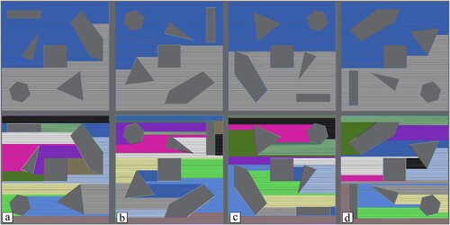
Figure 1. (a) SGMP configuration; (b) MG configuration. (c,d) An example of the PAD configuration (10) (c) robotic arms placements (c) and (d) printing areas.
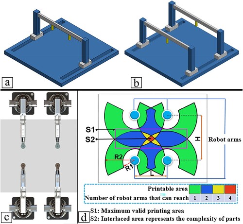
The MG configuration (b) is more advanced than SGMP as the printheads in this configuration are completely independent in both planar axes as well as the Z-axis, however, any two printheads are not allowed to cross each other. A similar configuration to the MG, called Multi-Nozzle (MN), was proposed [Citation15], but the Z-axis is shared among the printheads. However, the MN configuration is rarely used in the literature compared to the MG configuration as it introduces other constraints such limited Y-axis workspace. Bui et al. [Citation20] in their plastic cooperative printer used two readily available gantry 3D printers and combined them into a single machine that implements the MG configuration. The MG configuration was also utilised [Citation15] for cooperative concrete 3D printing which was tested virtually to build numerous building layouts using a 2 printhead system, the printing speed using the system almost doubled. The very first cooperative printer, Wachsmuth's research [Citation25], also incorporated the MG configuration. On the commercial side MG configuration was also employed. For example, Autodesk in its five printheads cooperative printing system, Project Escher, was configured in an MG configuration [Citation26]. Titan Robotics commercialised Project Escher further and developed it as a machine called Cronus [Citation27]. The Cronus cooperative printing system utilised a screw-based mechanism to extrude polymer pellets, allowing for the printing of large parts due to its high-volume capacity which exceeded 0.6 m3.
In the PAD configuration (c and d), the robotic arms are strategically positioned so that each has its own exclusive printing area, separate from those of other robots in the system, as well as a cooperative area shared with other robots [Citation10]. In this configuration, all robots operate independently and can freely cross paths without restrictions, in contrast to the SGMP or MG configurations. Shen et al. [Citation10], developed a PAD system for material extrusion based on 3-axis robotic arms. The authors optimised the position of the robots to allow them to cooperate in a small region. The path planner guaranteed that only one robot was allowed to work in the cooperative area to avoid collisions. Krishnamurthy et al. [Citation16] also employed the PAD configuration in their development of a cooperative printing system, specifically designed to fabricate interlocked layers. The positioning of the robots was determined according to the principles of Voronoi cells. Moreover, to prevent any potential collisions, both robots were restricted from operating within the central region simultaneously. Similarly, Zhang et al. [Citation19] proposed a PAD configuration for cooperative printing, based on the use of two mobile robots with mounted 6-axis robotic arms, cooperating in the fabrication of large-scale concrete parts. The mobile robots were responsible for the initial positioning of the system, while the robotic arms were responsible for the printing process. Systems with robotic arms are naturally configured as the PAD since the base is rooted to the ground at only one location and is not allowed to move, the MG is rooted at two locations as can be seen in b. However, other mechanical systems can employ the PAD configuration, such as the commercially available solution offered by WASP [Citation28]. They developed crane-like structures equipped with multiple printheads for advanced structural 3D printing applications.
The previously mentioned configurations present several limitations, especially in terms of the cooperative printing area. SGMP configuration capabilities are limited since the cooperation is only done on one planar axis. For example, parts that have symmetrical print lines around the shared axis can be fabricated cooperatively using systems based on the SGMP configuration. The other configurations are more sophisticated; however, they are still limited. Due to the nature of crossing prevention on the MG configuration, collisions are more frequent, and avoiding them cannot be solved without introducing printing delays [Citation12,Citation29]. Furthermore, preventing other printheads from crossing results in a large reduction of the cooperative printing space. a shows the printing areas of the MG configuration for two printheads system. In this system, the single and cooperative areas dynamically change during the motion of the printheads due to cross-prevention. This constraint prohibits any two printheads (each mounted on its own gantry system) from crossing each other's paths during the printing process. The implication of this restriction is that although each printhead in the MG configuration operates independently in both planar axes as well as the Z-axis, they are not allowed to intersect or pass over each other's paths as can be seen in b. Consequently, the contour of a part cannot be printed cooperatively in the MG configuration unless one of the printheads remains idle, this issue is also presented in the PAD configuration. In contrast to the MG configuration, the cooperative area in the PAD configuration is static, however, it is determined by the initial placement of the robots. The cooperative printing area is the intersection between the workspace of at least two robots, and it is usually significantly smaller than the single printing area as shown in d and b which resembles the printing area depicted in [Citation19]. Additionally, as the number of robots increases in either the MG or PAD configurations, the number of cooperative areas also grows, resulting in a seam between any two adjacent areas. This is evident in Bhatt et al.'s work [Citation21] on Wire Arc AM using three cooperative robotic arms configured as PAD. The sample part printed exhibits three seams, coinciding with three cooperative areas, which significantly diminishes the part's mechanical properties. This is also visible in parts printed by other systems such as Project Escher and Cronus machines [Citation17,Citation26,Citation27]. Moreover, the PAD configuration has been limited to mechanical systems with revolute links, making collision avoidance and checking more complex, as the different links of any arm might interfere with or block the motion of the other robots in the cooperative area.
Figure 2. Single and cooperative printing areas for (a) MG configuration; (b) PAD configuration. (c) MA configuration.
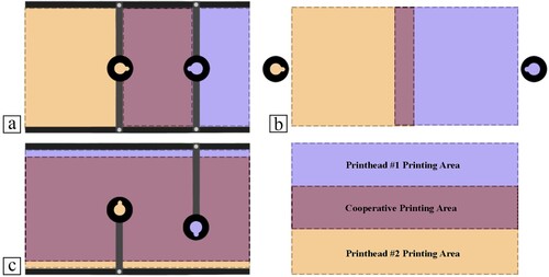
To address these limitations, this paper proposes a new configuration, called the Multi-arm (MA) configuration. As will be shown, the MA configuration can cooperatively print parts more efficiently than other configurations. Furthermore, the cooperative area of the MA configuration (c) spans the whole workspace of the system, unless a portion is designated as a safety region. Additionally, the developed machine is constructed without any revolute joint which makes collision avoidance and checking much simpler for the MA configuration.
2.2. Cooperative printing path planning
Cooperative printing's main challenges include toolpath planning and collision detection and avoidance [Citation7]. Several toolpath planning algorithms have been developed in the literature. Jiang et al. [Citation8] determined the required print paths for each layer using Evolutionary algorithms. Simulated Annealing and Straddle Test methods were used to generate toolpaths for a system of cooperative robotic arms [Citation10]. Other methods include Tabu Search for an MG system [Citation20] and Longest Processing Time for scheduling [Citation9]. Nonetheless, the primary objective of all algorithms in the literature is to reduce printing time [Citation15,Citation19,Citation30], with no emphasis placed on equalising the time spent by each printhead. Minimising the difference between the largest and smallest printing time of the printheads helps in preventing issues such as wear and fatigue of one printhead. Furthermore, lower differences allow both printheads to finish and start the next layer within a short time which reduces the need for Z-axis collision checking. Thus, in our work, the developed algorithms implicitly optimise for lower differences between the printheads.
Solving for toolpaths in cooperative printing is an optimisation problem [Citation7], and constraints are employed to find feasible solutions. However, existing literature on cooperative printing tends to prevent different printheads from operating on distinct layers, treating it as a constraint. For example, Zhang and Khoshnevis [Citation15] designed their concrete cooperative printer such that all printheads must initiate work on the same layer simultaneously; if one printhead finishes early, it must pause and wait on the side. A similar constraint is introduced in [Citation10], where any robot completing its task early must halt until all other robots finish. Other studies, such as Wang et al. [Citation13], implicitly assume that all printheads complete their work before starting the next layer, as seen in their use of multi-head slicing algorithms for cooperative printing. This constraint is also present in various other works such as [Citation8,Citation9,Citation16]. In our work, if a printhead completes its layer, it is permitted to begin work on the subsequent layer without waiting for the other printhead. However, this introduces additional challenges, such as the possibility of a printhead on a higher layer printing over a yet-to-be-printed line or a lower printhead colliding with a line already printed by a higher printhead.
Cooperative printing path planning must comprise a collision avoidance strategy to solve collisions in the toolpaths. Collision avoidance can be performed by either replanning the toolpaths or by applying a Delay-Based Method (DBM) [Citation8,Citation9]. DBM adds a delay to one of the printheads or alters its speed to avoid potential collisions. DBM was also applied to prevent the printheads from working on different layers [Citation15]. However, this approach presents several limitations in terms of path planning and the quality of the produced parts. For example, due to the frequent stopping of the printhead, the number of accelerations and decelerations increases, which increases the overall vibrations. Furthermore, as this paper shows, the total printing time is on average higher than other methods that do not add delays. Additionally, for several applications such as concrete printing applications or printing fast-curing polymeric mixtures, stopping a printhead for more than a specified time may solidify the material inside the printhead. Finally, there are cases where adding delays does not avoid potential collisions (e.g. when stopping at the start of the motion will still result in collisions). To address these limitations, this paper proposes an approach for solving collision avoidance called the Intermediate Point Method (IPM), as it generates an intermediate point for the traveling arm that connects the start and end positions with a collision-free line. The IPM method is based on the Velocity Obstacle Method (VOM), that was proposed for collision avoidance in mobile robots [Citation31], and that was also explored before in naval navigation applications for collision detection and avoidance [Citation32,Citation33]. However, these applications only investigate the direction of motion that avoids collisions without requiring arriving at a certain destination, which is not the case of AM applications. Moreover, the collidable objects are points with safety areas, while in this paper there is a link carrying the printhead, which is also collidable. This requires further analysis as the two links cannot pass each other to avoid collisions, even if the printheads are in collision-free paths.
This work was primarily inspired by the gaps identified in the existing literature. The MA configuration was developed to overcome the physical limitations highlighted in Section 2.1. Subsequently, this configuration served as a cornerstone for the development of advanced path planning algorithms, specifically targeting the challenges in cooperative printing as discussed. This paper presents several novel contributions, notably:
Introducing the Multi-arm configuration, which addresses the inefficiencies present in other cooperative printing configurations.
Developing a novel custom cooperative printing machine that implements the MA configuration along with establishing the required theoretical foundations for the system.
Formulating the toolpath allocation problem with the dual objective of minimising the overall printing time and reducing the difference between the longest and shortest printing times across all printheads. Additionally, allowing printheads to operate on different layers concurrently. This is complemented by novel preprocessing algorithms that enhance the efficiency of the path planning process.
Developing the IPM which allows higher avoidance rate and reduces the duration of the avoidance moves compared to the current DBM approach.
Investigating the theoretical maximum for printing time reduction reported in the literature and proving that our system surpasses it.
3. System overview
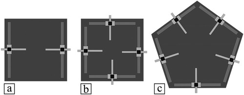
The MA configuration () proposed in this paper allows each printhead to be fully independent. In this configuration, each printhead is connected by a link to the base which forms an arm. All the motions are controlled without any revolute joint, making the workspace of each printhead a rectangle. The rectangular workspace allows each printhead in the system to reach any point in the workspace of other printhead if the printing platform is designed to have a similar area to the printhead workspace. This configuration offers scalability to accommodate any arbitrary number of printheads. However, as the number of printheads increases, managing collision avoidance becomes more complex and the system may become a PAD system. shows the MA configuration for systems incorporating up to five printheads. For any arbitrary number, , of printheads, the platform must be designed as a polygon with minimum of
sides.
Figure 3. Three MA configurations with a different number of printheads (a) two printheads (b) four printhead, and (c) five printheads.
The developed machine is shown in a. The structure, detailed in b, is made of 2020 aluminium extrusions (Misumi, USA). Each gantry has 5 identical NEMA 17 stepper motors (Trinamic, Germany): two for the XY-axes, two for the Z-axis, and one for the extruder. To account for the weight of the base that carries the printheads, the motion system of the Z-axis consists of two motors, 10 mm linear rods, and threaded rods (Misumi, USA). The XY-axes motion is controlled by two motors connected by belts (Creality, China), and comprises 5 linear rods with 8 mm in diameter. The developed system utilises two independent printheads and was designed to accommodate two additional ones. Each printhead is fed by an extruder operating with a 1.75 mm diameter filament. The components of each printhead are: a hotend and its fan, a part cooling fan, and an auto-bed-leveling sensor. The hotend is an E3D V6 (E3D, UK) with 0.4 mm nozzle diameter, and the build platform is an Ender 3 heated bed (Creality, China). The temperatures of the hotend and the build platform can reach 300 and 100 °C, respectively. The electronic boxes contain two SKR 2.0 (BIGTREETECH, China), both boards are connected to a Linux computer. However, since the system does not operate in real time, there is no direct communication between the printers. The role of the computer in this context is solely to transmit the files necessary to initiate the printing process. The machine does not have specific temperature requirements for its operation, and therefore, enclosures are generally not necessary. However, for printing materials which demand a controlled environment, such as PEEK, the use of an enclosure may be required.
Figure 4. (a) Developed MA cooperative printing system; (b) detailed CAD model of the MA gantry system (belts and cables are not shown).
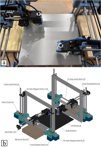
The total cost of the machine is estimated to be around $1,500. Excluding the cost of shared components, such as the printing platform and the main structure, the cost per printhead is approximately $600. Given that this project is in the research phase, it is important to note that these costs could be significantly reduced through cost optimisation strategies and mass production.
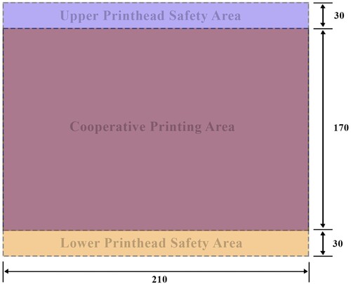
The cooperative printing area is 210 mm by 170 mm and each printhead can move up to 100 mm in the Z direction. The reach of each printhead in the Y-axis is 200 mm, and the distance between the base of the two printheads is 230 mm. This creates two non-cooperative areas with a 30 mm width at the base of each printhead, used as safety areas for path planning as collisions are impossible to occur there, and for the collision avoidance algorithm to generate collision-free paths. The different areas within the printing platform are shown in . Furthermore, the printhead size is designed to be as small as possible (30 mm), as reducing the printhead size allows the path planner to find solutions in a short time, as collisions occur less frequently with smaller printheads.
Figure 5. The cooperative and noncooperative safety areas of the machine. Dimensions are in mm.
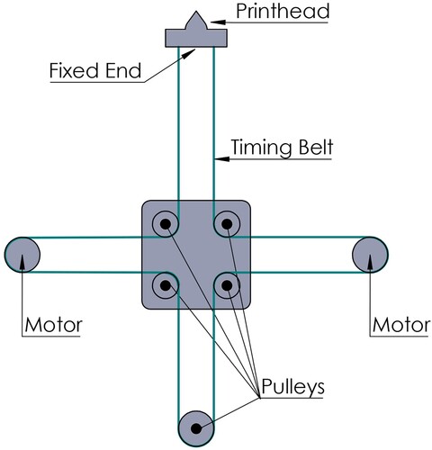
The planar motion is controlled using a single belt mechanism. In the T-bot mechanism (), a single timing belt starts from one end of the printhead and goes through a set of five idle pulleys and two motors, forming the letter T by returning to the other end of the printhead. Each printhead is controlled by a single timing belt. The printhead can move in the X or Y directions by combining the motion of the motors. The kinematic equation that dictates the motion is given by the following equation:
(1)
(1) where
and
are the changes in the X and Y positions of the printhead, respectively,
is the radius of the pulley and
and
are the changes in the angular positions of the two motors. Since each printhead is fixed to the base by a timing belt, the length of the link carrying the printhead is determined by the Y position of the printhead. This feature allows the printheads to cross each other without collision, which does not occur in other gantry configurations.
Figure 6. The T-bot mechanism that allows arm extension.
In order to simplify the path planning, the system was designed in a way that allows the neglection of acceleration, i.e. the printheads move with constant speed. Therefore, the system is characterised by very high accelerations (4000 mm/s2) and low speeds (20 mm/s).
4. Information flow
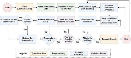
The typical information flow in AM comprises the generation of a CAD model, converting the CAD model into a file format such as STL, slicing the model, toolpath generation based on a specified layer pattern, and finally the conversion of the toolpath into a G-code [Citation7]. In our work for cooperative printing, three additional steps were considered between slicing and G-code generation (): preprocessing the generated toolpath, allocating the toolpaths to the different printheads, and collision checking and avoidance.
Figure 7. Information flow in the developed path planner.
4.1. Input data and preprocessing
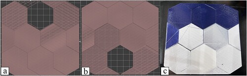
The input data to the developed cooperative printing software is generated by Cura (Ultimaker, Netherlands), which is a software used for slicing and planning 3D models for single-printhead material extrusion systems. The generated G-code is transferred to the developed software that parses the G-code and extracts all the required data such as the start and end positions of the print lines. Due to the nature of tessellating the CAD model, all the generated toolpaths from the slicer are straight lines. However, in the case of large and complex objects, the slicer generates thousands of print lines, making the path planning computationally expensive. Thus, we developed an algorithm that groups close lines in a single group, allowing the planner to deal with groups of lines instead of individual lines. It begins by selecting the initial print line and including it in a group. Then, the algorithm identifies nearby lines, adding them to the same group. The process of adding lines to the group ends either when a predetermined maximum length is reached or when the distance to the following print line surpasses a specific threshold. a–c shows the grouping method on a square layer, a shows the original 300 lines each given a random colour for visualisation purposes, the grouping method is not applied. b and c show the grouped toolpaths into 23 and 10 groups, respectively, each coloured column is a single group. The grouping algorithm allows the path planner to find solutions in a short time as the planner deals with a few groups instead of each individual line. Furthermore, grouping certain print lines into a single group allows the algorithm to easily account for different materials for multi-material AM. The default option in the preprocessor software is to only perform the grouping method on print lines that do not form a closed loop (such as the outside contour).
Figure 8. Grouping method: (a) no groups, (b) few groups, (c) a large number of groups. Loops breakage: (d) include all loops, (e) break all loops (f) break inner loops only.
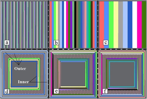
The preprocessor also comprises additional methods that help in generating an efficient toolpath in a shorter time. For example, for better surface quality a single loop is printed by one printhead in a continuous run. However, this increases the risk of collisions for large loops such as the contour of the layer. Thus, the preprocessor was designed to provide three options for handling loops: including all loops (d), breaking all loops (e), and breaking only inner loops (f). In , connected lines with the same colour are a single loop, while disconnected colours are non-looped print lines. The inclusion of all the loops helps in creating smooth contours without seems, albeit at the expense of increased path planning complexity to due to multiple long motions, particularly at the outer contour. On the other hand, breaking all the loops into individual lines offers an efficient path planning solution but may compromise the surface quality and mechanical strength of the part. A balanced alternative between these two options is to only include outer loops and break the loops inside the part.
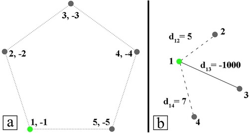
Furthermore, the preprocessor assigns two numbers, a positive and a negative number, to each node in a loop. Using this information, the planner must start at a positive number and goes CW or CCW until it reaches a node with a similar number to the starting one but with a different sign. This allows the points in a loop to be visited more than once, as the start point of a loop is also the end point. a presents an example where the planner, upon arriving at the loop, starts at node 1. Recognising the structure as a loop, the planner proceeds either CW or CCW until it hits node −1, thus closing the loop. This process results in a sequence of [1,2,3,4,5,−1]. If negative numbers were not assigned to the nodes, the planner would stop at node 5 in this instance, since node 1 is already marked as visited. This would prevent the completion of the loop as no node is allowed to be visited twice. Moreover, to ensure that the planner connects the start of the print line to its endpoint, the preprocessor assigns a negative value to the distance between them as the planner aims to reduce traveling motion distance. However, the distance between disconnected points is the Euclidean distance between them. This concept is demonstrated in b. In this scenario, the planner has visited node 1 and is determining the subsequent node to visit. While node 2 is the closest to node 1 with a distance of 5 units, choosing it would disrupt the print line connection between node 1 and node 3. Therefore, instead of assigning the Euclidean distance from node 1 to node 3, a large negative number is assigned to force the planner to connect the print line.
Figure 9. Examples of (a) the planner visiting a loop, and (b) the planner deciding which node to travel to from node 1. The green point is the current point for the planner.
The preprocessor end product is a list of groups and loops with numbered nodes and distances between the nodes. This list is forwarded to the toolpath allocator to plan a path for the printheads.
4.2. Toolpath allocation
The toolpath allocation problem is concerned with assigning print lines to different printheads with the objective of minimising the printing time while satisfying two main constraints. The first constraint is that all the print lines must be allocated to the printheads without any missing lines. The second constraint ensures that collisions do not occur with any printhead, link, or the part being built. For the objective function, the total printing time is the largest printing time among all the printheads, but the difference between the largest and smallest printing times can also be considered. Reducing the difference allows the printheads to start and finish the same layer concurrently, which helps in reducing the risk of collisions between the printhead and the part being built.
The toolpath allocation problem is treated as the Traveling Salesman Problem (TSP) and solved as if the system has only one printhead. When the toolpath that solves the problem is found, the algorithm divides the solution into two toolpaths, one for each printhead. The TSP is an NP-Hard problem [Citation34] and due to its complex nature, analytical solutions are nonexistent. Hence, heuristics remain the best approach to navigate the expansive solution space of the problem. Simulated Annealing (SA) has been widely used to solve the abstract problem of the TSP, a survey can be found in [Citation35]. In SA, the probability of accepting a new solution
over the current solution
is given by:
(2)
(2) where
is the temperature at that instant and
is the objective function. The acceptance probability is always 1 if the new solution is better than the current best-found solution.
The objective function for cooperative printing mainly considers the total printing time and the difference between the largest and smallest printing times. In our formulation, we relaxed the collision prevention constraint and augmented it in the objective function. We observed that when the printing time of both printheads is very large and approaches the printing time of a single-printhead machine, the possibilities of collisions sharply increase. In such situations, both printheads are actively printing without any idle moments. However, they often cover large distances in their travel lines, causing them to be at various distant points within short intervals, thereby increasing the risk of collisions. This will further increase the computation time as collision checking is the most expensive step in the path planning of cooperative printing. Thus, the objective function was modified to:
(3)
(3) where
corresponds to the largest printing time among the printheads,
is an integer with a value of 0 if collisions occur and 1 if the solution is collision-free, and
decides how the objective function changes if the solution reports no collisions. Based on an extensive trial and error procedure it was observed that the best results were achieved using
. This new objective function allows the algorithm to accept solutions with collisions allowing it to reach states where the largest printing time and the risk of collisions are lower. Furthermore, the objective function rewards solutions without collisions by reducing its value. The purpose of the SA heuristic is to serve as a global guiding mechanism directing the solution towards a point that results in acceptable performance. However, the specific mechanisms for altering toolpaths are dictated by separate algorithms as follows.
Since the original problem is treated as the TSP, an initial solution is required and generated using a greedy heuristic. The greedy heuristic starts at a random print line and passes over all the other print lines. The order of the print lines is chosen based on the distance from the current position to the start of the next line. Usually, the TSP requires to include all the nodes in the found solution. However, due to the groups and loops concept used in the preprocessing step, some nodes can be excluded allowing to reduce the computation time.
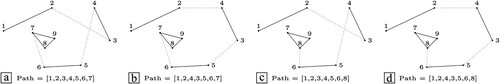
The developed algorithm uses two methods to alter the found path: swapping two travel lines and changing the loops’ order. The first method, known as 2OPT [Citation36], was further modified in order to work with the modified problem and with the grouping concept. The method takes two travel lines (e.g. and
in a), cuts them and connects them in reverse, as shown in b. In addition to changing the travel lines connections, this method also reverses the direction of traversing the lines between the original travel lines. Print lines are prevented from being changed as they are fixed and not allowed to change. The second method changes the entrance and exit of a loop by changing the order of the loop (e.g. [Citation7,Citation8,Citation9,Citation7] in a to [Citation8,Citation9,Citation7,Citation8] in c). It also removes the old starting node of the loop and replaces it with the new one. d shows the result of combining the two methods.
Figure 10. Different algorithms to locally modify the original path: (a) original toolpaths; (b) travel paths modifications; (c) loop order changes; (d) final result.
The proposed approach produces a single toolpath instead of a toolpath for each printhead. To generate a toolpath for the two printheads, the main toolpath is divided almost equally. Since the original toolpath is a loop, the division requires two nonconsecutive lines to be removed. These lines must be travel lines. The first travel line is chosen to be the largest one to further help in reducing the printing time, while the second is the one nearest to the middle point. To decide which printhead is assigned to a toolpath, the average of all points in a toolpath is computed and the closest average point to a printhead is assigned to that printhead. A faster way for deciding the assignment is to assign a printhead to the toolpath that has the nearest endpoint to it. This method guarantees that the difference between the largest and smallest printhead printing time is small, which is a reason why it was not included in the objective function.
After the main toolpath is divided into two toolpaths, the current position of each printhead is added to the start of the toolpaths. If the current layer is the last one, the home position of each printhead is added to the end of the toolpath. Then, the two toolpaths are verified by the collision checker algorithm, which checks the toolpaths line-by-line. If a collision is detected, the avoidance algorithm searches for an intermediate point that solves it and adds this point to the set of paths of the traveling printhead toolpath. In the cases where the collision is unavoidable, the collision checker algorithm stops and reports back that is 0 for the objective function.
The previous methods are repeated until the temperature of the SA reaches zero. If no feasible solution was found, the algorithms restart with a randomised initial solution. Otherwise, the planner proceeds to the next layer if the printed object requires more than one layer. However, since both printheads rarely finish at the same time, one printhead will proceed to the next layer before the other. In this case, the planner saves the remaining print lines for the late printhead and proceeds to solve the next toolpaths. The remained toolpaths are then added to the start of the toolpath of the late printhead during the division process. For multi-layer path planning, sometimes the planner cannot find a solution for a specific layer which might be due to the starting position of the two printheads at this layer. Thus, the planner is allowed to revise a previously planned layer if it cannot find a solution for a certain layer.
4.3. Collision detection and avoidance
Due to the introduction of multiple printheads, collisions may occur. Moreover, as the MA configuration allows each printhead to be fully independent, collisions become more complex. However, the MA configuration allows for more collision avoidance strategies as every printhead can move freely in all three spatial directions.
In this work, in addition to checking collisions in the XY plane, collisions on the Z-axis are also checked. Such collisions occur when the printheads are allowed to work on different layers at the same time, as a printhead on lower heights might collide with the lines printed by higher printheads. Due to this issue, some researchers enforce that all printheads work on the same layer, and if one printhead finishes early it must wait for all other printheads [Citation10,Citation15]. However, this decreases the performance of cooperative printing machines. We consider this case as a collision, and it is checked by computing the intersection between the printhead motion and the already printed line. An additional check is performed if the printhead on higher layers is about to deposit material over a line that is not finished by the printhead on lower heights. However, the dominant collisions are those that occur between the printheads. Two printheads are considered to be in a collision state if the smallest distance between them, at any instant of time, is smaller than a specified safety distance . The collision checking includes both the printhead and the link arm carrying it.
Collisions due to the motion of the arms can be avoided if the paths are changed. However, only travel paths are allowed to be modified as the print paths are given and unmodifiable. A travel movement is a motion between the end point of the current print line and the start point of the next print line. As this line is not a required line, it can be modified. Therefore, the current way to avoid collisions in path planning of cooperative printing is by introducing delays to the traveling printhead [Citation9].
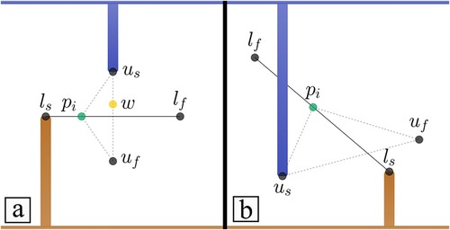
In this paper, we developed the concept of the Intermediate Point Method (IPM) for collision avoidance. The IPM generates a new point for the traveling arm that connects the end point of the current print line and the start point of the next line. This method breaks the original travel line into two lines connected by the intermediate point. a shows the lower arm (orange) printing a line that starts from ls and ends at lf, while the upper arm (blue) is about to travel from point us to point uf. To avoid collisions between arms, the upper arm can wait at point w until the lower arm passes the collision location. The IPM eliminates the need for waiting, by creating an intermediate point pi that must be travelled to before moving to the destination. Moreover, it requires that one of the motion types of the arms is a travel motion. One limitation of adding delays is that they cannot solve certain situations, e.g. when the print line passes over another arm, as shown in b, where the lower arm will collide with the upper arm even if it waits at the starting location. However, the IPM can be applied here to avoid the collision. In the mathematical formulation presented in this paper it is assumed that the lower arm is printing while the upper is traveling.
Figure 11. Two situations for collision avoidance, (a) a situation that can be avoided by delay-based methods; (b) a situation that cannot be avoided by delay-based methods.
To determine the location of the intermediate point we shift the starting position of the printing arm a distance ds, and find the location of collision between the shifted arm and the traveling arm. When the traveling arm reaches the shifted collision point, it should be ds away from the actual arm. The shift can be either forward or backward, depending on the position of both arms and the direction of movement. The calculation starts by finding the collision time tc at which the two printheads have the same position:
(4)
(4) where
and
are the relative x and y displacements between the printheads, respectively, and
and
are the relative x and y velocities, respectively. Therefore Equationequation (4)
(4)
(4) can be presented as follows:
(5)
(5) where
and
subscripts indicate the lower and upper arms, respectively. The only unknown is the velocity of the traveling printhead, which is assumed to correspond to the upper arm.
Knowing that:
(6)
(6) where
is the magnitude of the traveling velocity and
is the direction of the motion (i.e. the direction of the intermediate point). Combining equations Equation(5)
(5)
(5) and Equation(6)
(6)
(6) it is possible to obtain the following equation:
(7)
(7) The solution of Equationequation (7)
(7)
(7) gives the direction of motion that results in a direct collision between the two printheads. If the starting position of the printing printhead is shifted by a certain distance, e.g.
, the point of collision is actually the intermediate point
that eliminates the collision. Due to the shifting performed in the previous step, when the traveling printhead reaches
it should be
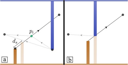
away from the other printhead. a shows the lower arm and its shifted copy for the calculations above. When the upper arm reaches the determined intermediate point, it collides with the shifted lower arm (b) which is
away from the real arm.
Figure 12. Visualisation of the shifting method. (a) Starting of the motion showing the shifted lower printhead in faded orange; (b) the upper printhead touches the shifted lower printhead at the intermediate point.
However, finding the position at which the traveling arm does not collide with the printing arm is not enough to ensure complete collision avoidance. This is because the collision might occur when the traveling arm moves from this new position to the destination, where collisions are not yet checked. In our implementation, if collisions occur in the second segment of the traveling arm, the intermediate point is changed by along the print line of the printing printhead, and the algorithm performs
iterations until collisions are completely avoided for both segments. However, the values of
and
affect the performance and resources consumed by the algorithm. Lower values of
might not escape the collision state, while higher values might skip over the optimum value and could result in a very large travel line. Based on extensive trial and error tests the values were set as
mm and
.
In the case of both printheads traveling, there are two options. The first option is to have a default printhead always considered printing and the other traveling. Alternatively, we can alternate between the two scenarios, having one considered printing while the other traveling, and determine which arrangement yields the shortest combined travel distance for both printheads.
4.4. Calibration and coordinate system transformation
The developed cooperative system is calibrated by modifying the workspace of the upper printhead relative to the lower printhead. This is performed by measuring the offset of the workspace of the upper printhead from the lower. The measurement data are acquired by requesting the two printheads to print a long horizontal line in the middle of the workspace. Based on the printed lines, possible deviations in the translation axes and the angular deviations are measured. A caliper is used to measure the deviation between the printed lines. Then, multiple concentric rectangles are printed using both printheads and if no deviations are found, the system is considered calibrated.
Finally, as the algorithms and calculations previously described were performed in the world frame, each toolpath must be transformed to the local frame of its arm. However, the world frame is assumed to be the frame of reference of the first printhead, the th printhead. Therefore, the transformation matrix is given by:
(8)
(8) where
is the index of the arm of interest,
and
are the X and Y distances from the world frame to the origin of the local frame of the
th arm, and
,
and
are the deviation errors (calibration step) from the designed angle, width, and height of each arm, respectively. The transformation matrix
assumes that the system is designed as an equilateral convex polygon with
sides. The transformations are only required in the XY plane and around the Z-axis. The auto-bed-levelling system used in the proposed system ensures that all printheads have the same height around the printing platform, thus avoiding the need for manual calibration.
5. Results and discussion
This section presents an evaluation of the MA configuration in cooperative printing, focusing on the efficacy of the IPM compared to the DBM in collision avoidance and efficiency. It contrasts the MA configuration with established systems like SGMP, MG, and PAD, highlighting its advantages in cooperative printing area and allocation. The section also examines the influence of layer patterns on printing efficiency and showcases practical demonstrations of the system's capabilities in printing complex single and multi-layer 3D objects. A comparative analysis with other state-of-the-art methods illustrates the proposed system's superiority in reducing printing time, establishing the MA configuration as a significant advancement in the field.
The evaluation is performed both virtually and physically. For the simulation side, a specialized software framework was developed using Unity 2021 and C# programming language. This software is also responsible for producing the toolpaths and implementing the path planning detailed in Section 4. Simulations are executed on a standalone personal computer (3.6 GHz Intel Core i7-9700 K CPU with 16 GB memory). The empirical side is performed on the custom developed machine, the design and technical specifications of which are comprehensively detailed in Section 3.
5.1. Simulation
5.1.1. The effect of using the IPM
A randomised simulation was developed in C# to compare the performance of the IPM over the DBM. The simulation process is shown in . It generates 2 million toolpaths (the maximum number of iterations considered in the software code) and assigns a pair of paths that are known to produce collisions between the two printheads. The simulation was performed two times, each with two different printhead length sizes. Larger printheads result in more collisions and lower avoidance rates. The obtained results are shown in .
Figure 13. The randomised simulation procedure used to compare the performance of both IPM and DBM.
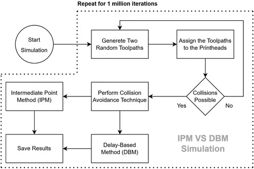
Table 1. Comparison of the IPM with DBM for collision avoidance.
As observed, results show that the proposed IPM method presents significantly better results than the DBM in terms of collision avoidance rate and the average duration of completing a travel movement. For a small printhead size, the IPM successfully avoided 13.7% of the collisions, almost 3 times higher than the DBM, and found travel moves that are 7.2% quicker than DBM. For both methods, results also show that the collision avoidance rate decreases by increasing printhead over the printing area ratio. Nevertheless, for the largest considered printhead, the IPM still produces paths that have a lower average duration compared to the DBM, reaching around 68% of the duration of a travel move using the DBM method. Similar results were obtained considering other geometries and features (Figure 17). Moreover, the IPM was found to be able to find 2.5 times more paths that are collision-free in comparison to DBM.
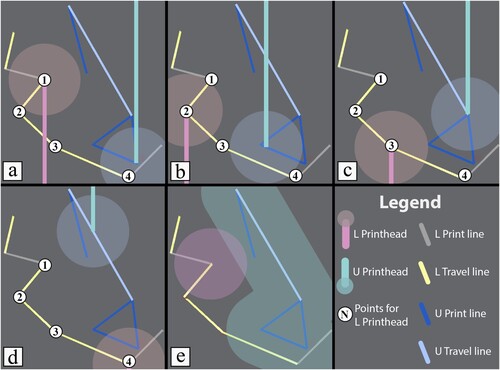
In addition to generating a single point to avoid collisions, the IPM can also generate multiple points based on the movement of the printhead. a–d are a series of images showing the simulation software working to plan several print and travel lines extracted from a 2D layer. The shaded regions around the printheads are the safety regions and when the regions intersect a collision occurs. In , the lower printhead finished printing the line that ends at Point (1) and prepares to travel to the line that starts at Point (4). However, the upper printhead is printing a triangular segment near the next task of the lower printhead. Therefore, the IPM generates an intermediate Point (2) that connects Point (1) to Point (4). This allows to avoid the collisions introduced by the current motion of both printheads. However, the next print line for the upper printhead introduces a new collision state, as the lower printhead travels directly from Point (2) to Point (4). Thus, the IPM generates a second intermediate point, Point (3), which connects Point (2) to Point (4), thus completely eliminating collisions. The generation of multiple intermediate points is necessary, as the planner does not know the future toolpaths of the printheads. Additionally, this situation cannot be addressed using DBM as there is no waiting place in the straight line between Point (1) and Point (4) that avoids the collision. This can be seen when the toolpath of the upper printhead is swept by the printing area of that printhead (e).
Figure 14. IPM generation of multiple points. (a–d) The motion of the two printheads doing several print and travel lines; (e) the swept area of the upper printhead toolpath and the area of the lower printhead at the starting position.
5.1.2. Multi-arm compared to other configurations
This section aims to conduct a comparative analysis between the MA configuration and the other established cooperative printing configurations discussed in Section 2.1. Such an examination aims to underscore the contributions of the MA configuration for cooperative printing.
SGMP Configuration: the main limitation of this configuration is that the printheads are coupled in both the Z-axis and one of the planar axes. This limitation becomes evident in scenarios involving asymmetric objects. The asymmetric triangle shown in a is a clear example of this limitation. If this part is divided using the middle point of the lower side and cooperatively printed using two printheads, the vertical print lines in the sides of the triangle will have unequal lengths, resulting in one of the printheads finishing earlier and remains idle until the other finishes so the fixed planar axis can change. Unless the part is symmetric, SGMP configuration will always have one of the printheads idle. For the proposed configuration, this asymmetric layer can be easily printed cooperatively efficiently, in fact, the right side of a shows the toolpaths generated using the developed algorithms, which resulted in a printing time reduction of almost 47% without any printhead being idle in the whole printing process. Furthermore, long single lines are impossible to cooperatively print using the SGMP configuration, e.g. c, unless it is divided into two parts, which in turns have negative impact on both the quality and the mechanical properties of the part.
Figure 15. Problematic model and the specific problematic layer for (a) SGMP, (b) PAD, and (c) MG configurations. The right side shows how the MA configuration solves each problematic layer efficiently. The blue and grey regions correspond to the upper and lower printheads, respectively.
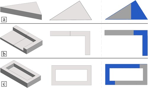
PAD Configuration: this configuration, though effective in specific applications, faces challenges due to its inherent fixed configuration. The asymmetricity problem of the SGMP is not an issue for the PAD configuration as the printheads are not coupled in any axes. In fact, machines implementing the PAD configuration can print any layer efficiently, providing the layer can be divided into equal parts. However, due to the fixed nature of the PAD configuration, not every layer in a part can be divided equally. b shows a part in which the centre line changes across the layers, making the printing areas unequal across the layers. The equal division line in the object shown in b varies between the two features of that object. The lower feature is a rectangle with an equal division line located at the centre of the part, while the upper L-shaped feature has an equal division line on the right. The maximum printing time reduction of the lower feature, if printed by a PAD system consisting of two printheads, is 50%, if the division line is at the centre of the rectangle. However, using the same division line but for the upper feature, the maximum printing time reduction is 34%. This issue can be avoided in PAD systems if the division line is recalculated at every layer, but this is difficult to implement as the cooperative area in these systems is very small. Contrary, the MA configuration is able to achieve consistent printing time reduction when planning such objects. For example, the L-shaped feature planned using the developed algorithms (the right of b) achieved a 47.5% printing time reduction.
MG Configuration: all of the challenges previously mentioned for the PAD are easily avoided by the MG configuration as the printheads in this configuration do not have a fixed workspace, in fact, the printing area dynamically changes due to the cross-prevention feature of the MG. However, this is also a large restriction for the MG configuration. This prevents the system from printing a long line that spans the workspace of multiple gantries. One example is the part shown in c, which contains multiple layers that have several continuous long lines. Any system implementing the MG configuration cannot print the outer walls of the part in c cooperatively. To print those long lines, the cooperative mode must be stopped, and one of the printheads must print it without cooperating with the other printheads, which drastically reduces the efficiency of these systems. For MA systems, long lines are possible to be printed during the cooperative mode. This can be seen in the right side of c, in which the developed planner generated toolpaths that allow the outer contour to be printed in cooperative mode. In this toolpath, when one arm prints the lower part of the layer, the blue arm prints the upper wall contour, and vice versa for the lower wall contour. However, long lines have higher collision chances, thus increasing the computation time as discussed in the next sections.
5.1.3. The effect of layer patterns and rotations
Several layer patterns used for material extrusion path planning include: rectilinear, triangles, and Hilbert curves [Citation37]. In the case of planning a square layer with 10% infill, the rectilinear layer pattern with a 0° angle between printed filaments is 70% more likely to find solutions compared to a triangle layer pattern. This is due to the fact that the triangle layer pattern covers the layer with large triangles, which significantly increases the risk of collisions as a printhead will be in multiple distant locations in shorter times. Other layer-filling patterns, such as Hilbert curves, create a large number of small lines, significantly slowing the toolpath allocation process and increasing memory usage even if the grouping method is used. However, Hilbert curves are efficient when considering collision detection and avoidance as those lines are clustered in very narrow regions. Based on the obtained results the rectilinear layer pattern that showed the best performance and fastest computation time.
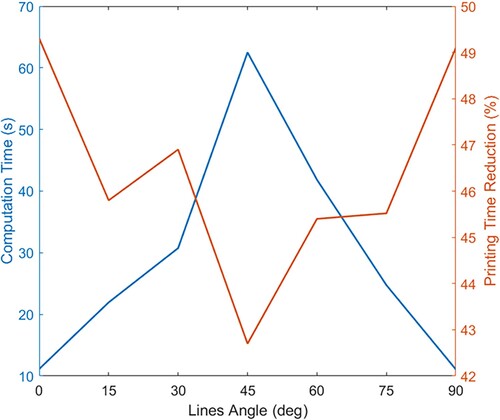
In a rectilinear layer pattern, the layer is filled with multiple parallel lines with an angle specified by the user. To choose the best angle for the rectilinear layer pattern, the developed algorithms were used to plan toolpaths for the seven angles in the X-axis shown in . The planned layer is a borderless square with a 170 mm side length and each printhead has a 30 mm safety distance. The results, shown in , represent the effect of the lines angle on both the computation time and the printing time reduction percentage. Both 0° and 90° showed similar performance for path planning and produced the best results among all tested angles. The reason is that these two angles produce the smallest possible line lengths for a rectilinear layer pattern. This is further supported by examining the effect of 45° lines on the performance. As can be seen from the figure, 45° lines have the lowest printing time reduction and the highest processing time. This is mainly attributed to the large diagonal lines produced by the 45° layer pattern. The effect of the other angles is worsened as the angles get closer to 45°. However, the effect is not symmetrical around the 45° angle, as angles closer to 0° allow for better results than those closer to 90°. This is due to the grouping algorithm, which creates unsymmetric groups for angles that are symmetrical around the 45° angle.
Figure 16. Effect of rectilinear pattern angles on both computation time and printing time reduction.
Next, the developed path planner is used to plan the toolpaths of a single layer rotated to different orientations. The layer illustrated in underwent rotations at four distinct angles: 0°, 90°, 180°, and 270°. Throughout these variations, the threshold length for the grouping algorithm was consistently maintained at 2500 mm. The time required for single-printhead printing of each layer remained relatively constant, approximately 25 ± 0.04 min, indicating that the rotational adjustments imparted negligible impact on the printing duration. Conversely, when utilising the cooperative printing system, the geometrical orientation of the layer significantly influenced several parameters, including the efficacy of the grouping method and the probability of collision occurrences. Consequently, the cumulative printing times for the four layers, as depicted in , were 12.89, 12.77, 12.98, and 12.91 min, respectively. Notably, the variation between the maximum and minimum times was approximately 0.21 min, a factor nearly quintuple to that one observed for single-printhead printing. It was anticipated that layers rotated by 180° (as shown from a to c and from b to d) would exhibit analogous reductions in printing time, as in this case the upper printhead becomes the lower printhead and vice versa. However, the disparities observed are primarily a consequence of the grouping algorithm as can be seen from the bottom row of , the 180° rotation created different groups for these layers. For objects with large number of layers, selecting an orientation that minimises printing time is critical, as even marginal differences can accumulate across layers, thereby affecting the overall efficiency of the cooperative printing process.
Figure 17. A single layer at four distinct angles: (a) 0°, (b) 90°, (c) 180°, (d) and 270°. Top: the generated toolpaths, Bottom: the groups generated from the grouping method.
5.1.4. Comparative analysis of printing time reduction
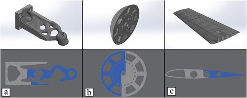
In order to investigate the efficiency of different toolpath planning methods, focusing on their ability to reduce printing time, different objects were considered (): the topology optimised bracket [Citation38], the nose of a wind turbine [Citation39], and a wing of an airplane [Citation40]. These objects were sliced and prepared with software parameters consistent with those discussed in Section 5.2.1.
Figure 18. The three different objects with layers tested for cooperative printing using the developed algorithms. (a) Topology optimised bracket (38), (b) nose of a wind turbine (39), and (c) wing of an airplane (40). The top images show the CAD models and the bottom images correspond to sample layers from the models where the system has generated toolpaths for two printheads. Blue and grey regions correspond to the upper and lower printheads, respectively.
To benchmark our approach against state-of-the-art methods, we compared the performance of the proposed system performance with Netfabb Multi-Gantry Engine [Citation35] which is the slicing software for projects such as Cronus and Escher [Citation26,Citation27]. Moreover, the system is also compared to the algorithm Tabu Search Collision Checking and Resolution (TS-CCR) developed by Bui et al. [Citation21]. The results are as follows:
Netfabb Software: the reported layers printing time reduction for the bracket, turbine nose, and airplane wing were 36.7%, 37.1% and 28.6%, respectively [Citation20].
Bui et al. (TS-CCR): this algorithm showed a reduction in printing time of 44.4% for the bracket, 43.6% for the turbine nose, and 38.1% for the airplane wing [Citation20].
Proposed System: The most notable results were seen with the proposed method. The reductions achieved for the bracket, turbine nose, and airplane wing were 49.3%, 48.2% and 48.1%, respectively.
The comparison yields insightful observations. While the Netfabb software provided substantial reductions, the algorithm developed by Bui et al. [Citation21] improved upon these numbers. This might be attributed to the use of the Tabu Search mechanism, which is designed for efficient optimisation. However, the layers planned using our proposed method showed a remarkable improvement over both Netfabb and TS-CCR. Our approach consistently resulted in reductions close to or exceeding 48% across all tested layers. This indicates that the developed system optimises the printing process even further. The bottom of shows sample layers from each object and generated toolpaths from our path planning algorithm.
The computational time to plan the specific layers shown in was limited to 7 min in the work of Bui et al [Citation21]. When projecting this to an object of tens or hundreds of layers might result in hours of computation time. However, using our proposed method the layers were solved in a maximum of 7.5 s. A significant portion of this time efficiency can be attributed to our grouping algorithm. Without this algorithm, the maximum computational time jumps to 35 s.
5.2. Experimental works
5.2.1. Experimental setup
This section details the setup for all the experimental work, including slicing parameters, software configuration, and the material used.
The slicing software used in this research is the Ultimaker Cura with the following configuration: 0.4 mm line width, 0° rectilinear layer pattern, and 2 walls. Top and bottom layers are sliced with 100% infill and the remaining layers with 10% infill. The layer height was 0.2 mm and the printing temperatures were 215°C hotend temperature and 55°C bed temperature. The materials used are white and blue PLA for the lower and upper printheads, respectively.
For the cooperative path planning a safety distance of 50 mm was used. Any distance below this is considered a collision and dealt with by the IPM algorithm. The grouping algorithm used around 2000mm total length for a single group threshold.
In the results presented below, the printing time reduction is calculated as the ratio of the time taken by our cooperative system to print a layer to the time required by a single-printhead system to print the same layer. The single-printhead system's toolpaths are derived using the Cura slicing software.
Before initiating the printing process, all printheads underwent a one-time calibration using the methods outlined in Section 4.4. Upon completion of this calibration, each printhead proceeded to probe the entire printing area with the integrated auto-bed-levelling sensor. This procedure was implemented to calculate the height deviation across the printing surface. This height deviation measurement is a critical step in ensuring uniform layer deposition and consistent print quality throughout the printing process.
5.2.2. Cooperative printing of a single layer
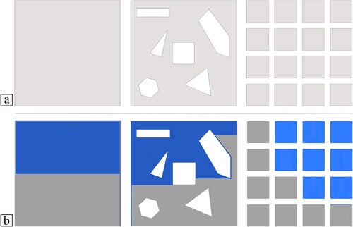
The proposed system and developed algorithms were tested to plan the toolpaths for several single-layer square objects. These layers, shown in , are as follows: a 120 mm square without any feature (Case 1), a 120 mm square with multiple polygonal holes (Case 2), and a grid of equally distanced squares (Case 3).
Figure 19. The three different layers tested for cooperative printing using the developed system. (a) A model of each layer and (b) the generated toolpaths for two printheads MA system. In (b), blue and grey regions correspond to the upper and lower printheads, respectively.
A similar reduction in the printing line was achieved for all considered cases. The maximum reduction time of each layer is around 49.5% (Case 3) with an average of 47% printing time reduction. For a better comparison, the grouping algorithm was not utilised as the different number of groups affect the layers’ path planning. The main difference between the three cases is related to their complexity during cooperative path planning. The layer’s complexity for cooperative printing path planning is directly related to the ratio of the number of collisions over the total number of found toolpaths. The collision ratio for the three cases is 7.66%, 3.40%, and 0.44%, respectively. The reason for these large differences is the number of long lines in the layer. It is clear that Case 1 has the longest lines among the three cases, thus being the most complex. On the other hand, Case 3 consists of multiple squares of 25 mm in length, and the longest line in this layer is about 20% of the longest line in the other cases. The collision ratio can be reduced by reducing or eliminating the longest line. For example, removing the contour in Case 2 reduces the collision ratio from 3.40% to 0.71%.
b shows the toolpaths for the three cases generated by the developed cooperative printing algorithm for the MA configuration. In this figure, the grey area is the toolpath for the lower printhead while the blue one is the toolpath of the upper printhead. In Case 1, the planner found toolpaths that almost divide the layer into two equal parts, thus reducing the printing time in half. However, the found toolpaths did not share the walls evenly, e.g. the lower arm had to print one of the walls on the top as well as both walls on the bottom of the layer. However, in Case 2, the holes break the long lines which allowed the planner to split the walls evenly between the printheads. Finally, the path planning of Case 3 is largely dependent on how the grouping algorithm generates the groups. For the optimum printing time reduction, each square should be assigned to a single group so each printhead prints half of the squares.
The three cases were also printed using the developed cooperative printing machine and the results are shown in . Each layer was printed with the previously mentioned settings. The developed system perfectly printed all layers without any major issues, such as collision or mid-print failure. The single-printhead printing time for the three cases is 30, 25 and 22 min, respectively. Using the cooperative printing system, the printing time was reduced to 15.8, 13 and 11.6 min, respectively.
Figure 20. Cooperative printing of three different single-layer objects.
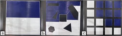
a is the printed layer for the square layer without any other features. The printed layer did not show any first-layer issues, as the system was well-calibrated on the Z-axis. The second Case (b) showed similar quality. However, there are visible stringing lines due to material leaking out the nozzle as the printhead travels without printing, and this is also visible in c, but easily removed as it occurred outside of the printed squares. This can be reduced by implementing retraction, which was not considered here because it violates the acceleration assumption as the printhead has to stop during retraction and deretraction. In the lower-left corner of b, the stringing line of the blue filament shows the effect of the IPM for collision avoidance. The planner created a joint point between the white and blue lines above the hexagonal hole to form an intermediate point, so the upper arm does not collide with the lower arm traveling to the left side of the square hole.
5.2.3. Cooperative printing of a full 3D object
Two 3D objects were considered to test the proposed cooperative printing system. The first multi-layer object is a section of a hexagonally tiled object (). Each tile is a regular hexagon circumscribed with a 45 mm diameter circle, and the total size of the object is 120 mm × 120 mm × 10 mm. The printing process was conducted considering the same Cura slicing settings, materials, and printing conditions previously discussed. However, the rectilinear angle was set to alternate between 120° and −120°. This object consists of a total of 50 layers.
Figure 21. Toolpaths of the (a) lower and (b) upper arms, and (c) the printed object.
Inspecting the toolpaths (a and b), the hexagonal tiles in the middle of the bottom and top row of all layers were only assigned to the printheads that have the nearest bases to those tiles. This is attributed to the collision checker preventing the opposite printhead to work on such areas to reduce the collision possibilities. For example, when the lower printhead approaches the tiles on the top-middle of the part, the upper printhead is restricted to only a third of the remaining workspace and makes the remaining 67% of the workspace unreachable without collisions. Since we used two materials presenting different colours (c), the effect of stacking different coloured layers is evident in the hexagonal tiles’ overall colours. The two tiles on the middle bottom and middle top have clear white and blue colours, respectively, as they were printed by only one printhead. On the other hand, the hexagonal tile on the middle right has a grey colour as it was mainly printed in blue colour, but the top layer was printed by the white printhead.
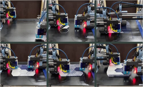
The total time required for a single-printhead machine to print this object is 6.42 h. However, the proposed cooperative printing system completed it in 3.36 h, which corresponds to a printing time reduction of around 48%. A sequence of images showing the printing process is presented in .
Figure 22. Images of the machine printing the hexagonally tiled object. The full video is available at: https://youtu.be/mrDgoHUAMtE?si = fGEjtKyiKE2E-yTW.
It is frequently reported in the literature, that the maximum printing time reduction for cooperative printing systems is , where
is the number of printheads [Citation13]. However, this only considers a reduction of printing time due to the different printheads sharing the print lines in the layer. In several objects, such as those with distant features in the same layer, travel lines constitute a large percentage of the total printing time, as the printhead must travel to those features which increases the total printing time. For cooperative printing, travel lines can be reduced as they are not required for the fabrication of the part. So, the distant features in a layer can be printed by the different printheads in the system, which eliminates the long travel line allowing the cooperative system to achieve a higher printing time reduction than the one reported in the literature.
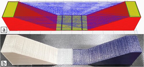
a shows an example of such objects. In this case, the bottom layer is a single layer without a significant number of travel lines, but higher layers have two distant regions requiring long travel lines. The rest of the object consists of 100 layers and in each layer the printhead must travel between the two features. The blue lines in a are the travel lines for a single-printhead system, which correspond to around 15% of the total printing time. Therefore, the total printing time for this object, considering a single-printhead machine, is 1.84 h. However, the proposed system and the developed cooperative path planning printed it in 0.81 h (b), a reduction of 56% that exceeds the 50% value expected for a system comprising two printheads. One of the side effects of travel lines is the requirement of retraction to eliminate stringing, which is essential to print the object in . As retraction requires frequent stops, enabling retraction increases the single-printhead printing time to 2.05 h, which increases our reduction ratio to 60.5%.
Figure 23. An object with distant features. (a) Single-print head toolpath (blue lines are the travel lines), and (b) 3D printed part with the developed machine.
5.3. Discussion
The results in the previous sections revealed significant insights into the capabilities of the MA configuration for cooperative printing, as well as the improvements of the developed algorithms. This section discusses these results and their effects on cooperative printing.
The IPM fundamentally redefines collision avoidance in cooperative printing by offering a dynamic solution that diverges significantly from DBM. The IPM not only demonstrates a higher collision avoidance rate but also maintains shorter travel durations, a critical factor in enhancing operational efficiency and productivity in additive manufacturing. As unresolvable collision paths require replanning problematic paths, and sometimes the whole layer, the IPM produces feasible paths significantly faster than DBM. This is because collision-checking and replanning a path due to collisions is a computationally expensive step in cooperative path planning. For instance, on average, collision detection and checking account for about 53% of the total time spent in planning.
Furthermore, the developed preprocessing algorithms, particularly the grouping algorithm, played a pivotal role in optimizing the printing process. This algorithm significantly reduced the computational time for path planning. In comparative tests, layers planned with the proposed method were solved in a maximum of 7.5 s, a significant contrast to the several minutes reported in other studies as was shown in Section 5.1.4. This reduction in the computational time is critical when considering the potential hours required for planning multi-layer objects.
One of the key elements from the study is the notable efficiency of the MA configuration in reducing printing time – approximately 48% compared to a single-printhead system for all the parts shown. This was shown to both single and multi-layer objects. Almost doubling the speed of AM in various scenarios is a large advantage of cooperative systems that can allow it to compete with other manufacturing technologies in mass production. Also, this speed improvement is further needed for large-scale AM such as in construction where buildings can take long printing times to be completed. The physical configuration of the MA is particularly important in the field of construction as cranes that carry concrete printheads can be formed as MA and is widely used in concrete applications [Citation28]. This efficiency is particularly noteworthy in the context of objects with features distanced within the same layer, where traditional printing systems incur considerable time due to necessary travel lines. The MA configuration, by allowing different printheads to print separate features, effectively eliminates these travel lines, thereby achieving greater time reductions than previously reported in cooperative printing systems.
5.4. Limitations
While the proposed MA configuration and its accompanying algorithms offer significant improvements in cooperative printing, several limitations must be acknowledged. Understanding these limitations is crucial for further development and practical implementation of this technology.
The discussion in Section 3 primarily focuses on scalability in relation to the number of printheads, aiming to further decrease printing time. However, a critical aspect of scalability concerns increasing the printing area. To achieve a larger printing area, it is necessary to increase the length of the link arm for each printhead. Yet, as these arms are fixed at the base, they function as cantilever beams. A fundamental problem with cantilever beams is the increase in deformation and vibration at their endpoints as the length of the beam is extended. To tackle deformation issues, the strategy involves calculating deflections at specific points and adjusting the Z-axis motor accordingly to counteract these deflections. Vibration presents a more complex challenge, as it dynamically varies due to numerous factors, including the acceleration of the Z-axis motor.
A static analysis was performed to measure the deformation issues for the machine. Two locations were analysed 10 and 200 mm from the home position in the Y-axis. As expected, the deformation is minimum when the printhead is closer to the home position, as it resulted in only 0.018 mm deviation. However, at the maximum reach in the Y-axis, the deformation changed significantly to 1.67 mm. Despite this considerable deviation, the system compensates for it. This is achieved through the integration of an auto-bed-levelling sensor mounted near the printhead, which has a stroke length of 6.6 mm. The sensor scans the printing area and measures the gap between the printhead and the printing platform, then the firmware automatically adjusts the printhead Z position, ensuring uniformity across the print platform. The next evaluation concerns vibration effects. This was performed by analysing the dynamics of the machine at the end of the acceleration and deceleration of the motors. shows the printhead position vibrations for the Z-axis motor at both locations. As expected, the vibration is minimum when the printhead is close to the home position as the effect of the cantilever beam is minimum. However, when the arm is extended to maximum reach, the positional error jumps to 0.02 mm, roughly ten times the error when the reach is minimum. In our setup, employing a 0.2 mm layer height, the vibrations caused by the cantilever-like arms in the multi-arm configuration are negligible. However, this highlights the limitations of using such arms in this configuration. These issues must be considered when adopting the configuration presented in this work.
Figure 24. The effect of vibrations on the position of the printhead. (a) The effect at 10 mm on the Y-axis; (b) the effect at 200 mm on the Y-axis.
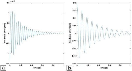
The MA configuration is a versatile design adaptable to various mechanical systems, including mobile robots as previously showcased [Citation41]. However, this configuration inherently restricts movement to translational motion only, which in turn limits the capabilities of the mobile robot. The absence of rotational motion around the robot's centre is particularly noticeable in scenarios where such movement could be advantageous, such as in collision avoidance. The ability to rotate can significantly enhance a mobile robot's manoeuvrability and effectiveness in navigating complex environments such as when more than two printheads cooperate. Therefore, while the MA configuration offers certain benefits, its limitation in rotational dynamics needs to be considered when integrating it into mobile robots.
One limitation of this work, particularly on the software side, is that the collision checking and avoidance algorithms, including the IPM, are specifically tailored for the MA configuration. While the IPM could potentially be adapted for other configurations like the PAD by using the formulation presented in this study as a starting point, its applicability to configurations such as the MG and SGMP is limited. This limitation stems from the inherent cross-prevention nature of MG and SGMP systems, which fundamentally conflicts with the operational principles of the IPM.
6. Conclusions
This work introduces a new approach for AM through the development of a novel Multi-arm (MA) gantry system for cooperative printing. This system addresses the inherent limitations of current AM processes, primarily the slow printing speed, by enabling multiple printheads to operate concurrently and independently. The paper shows that the MA configuration surpasses existing cooperative printing configurations in efficiency and versatility.
The MA configuration allows for full independence of each printhead, providing a significant advantage over other configurations explored in the literature. It demonstrates a marked improvement in cooperative printing areas, enabling the printing of complex parts more efficiently. Notably, the cooperative area in the MA configuration spans the entire workspace, a distinct improvement over the SGMP and MG configurations. The research also introduced the Intermediate Point Method (IPM) for collision avoidance. The IPM outperforms existing Delay-Based Methods (DBM) by offering a higher rate of collision avoidance and reducing the duration of travel movements. This method is particularly advantageous in scenarios where traditional DBM approaches are ineffective.
The study's empirical testing highlights the system's capability to achieve significant time reductions in printing, increasing the printing speed by almost a double compared to conventional AM systems. In specific cases, it even surpasses the theoretical maximum printing time reduction ratio commonly cited in cooperative printing literature. The system's efficacy is further validated through the successful printing of various single and multi-layered objects, demonstrating its practical applicability and robustness.
In future research, we aim to leverage the system to dive deeper into the potential of cooperative printing for advanced AM, investigating multi-material and functional components. Additionally, we aim to extend the application of this technology to large-scale construction projects. Given the inherent time-saving benefits of cooperative printing, its implementation in construction could revolutionize the speed and efficiency of building processes. Another key area of development will be the improvement of the IPM algorithm. Our goal is to evolve this algorithm beyond its current capabilities in the XY plane, enabling it to effectively manage collision avoidance in the Z-axis as well. Moreover, in the future, we aim to focus extensively on the interfaces created when parts are printed using multiple printheads. This investigation will delve into how the interface geometries, formed by distinct regions being printed by separate printheads, affect the mechanical properties of the final printed parts. An important aspect will be to explore the optimization of these interfaces, potentially using our preprocessing grouping method, to enhance the strength and bonding of the parts.
Disclosure statement
No potential conflict of interest was reported by the author(s).
Data availability statement
The data that support the findings of this study are available from the corresponding author upon reasonable request.
Additional information
Funding
References
- Sepasgozar SME, Shi A, Yang L, Shirowzhan S, Edwards DJ. Additive manufacturing applications for industry 4.0: A systematic critical review. Buildings. 2020;10(12):231-261. doi:10.3390/buildings10120231
- Sabourin E, Houser SA, Helge Bøhn J. Adaptive slicing using stepwise uniform refinement. Rapid Prototyp J. 1996;2(4):20–26. doi:10.1108/13552549610153370
- Wu C, Dai C, Fang G, et al. RoboFDM: A robotic system for support-free fabrication using FDM. 2017 IEEE International Conference on Robotics and Automation (ICRA)2017: 1175–1180. doi:10.1109/icra.2017.7989140
- Shah J, Snider B, Clarke T, Kozutsky S, Lacki M, Hosseini A. Large-scale 3D printers for additive manufacturing: design considerations and challenges. The International Journal of Advanced Manufacturing Technology. 2019;104(9-12):3679-3693. https://doi.org/10.1007/s00170-019-04074-6.
- Mazzei Capote GA, Oehlmann PEV, Blanco Campos JC, et al. Trends in force and print speed in material extrusion. Additive Manufacturing. 2021;46:102141. doi:10.1016/j.addma.2021.102141
- Geng P, Zhao J, Wu W, et al. Investigation of void formation in friction stir welding of 7N01 aluminum alloy. J Manuf Process. 2019;37:139–173. doi:10.1016/j.jmapro.2018.11.019
- Alhijaily A, Kilic ZM, Bartolo ANP. Teams of robots in additive manufacturing: a review. Virtual Phys Prototyp. 2023;18(1):2162929. doi:10.1080/17452759.2022.2162929
- Jiang Z, Wang H, Sun Y. Improved co-scheduling of multi-layer printing path scanning for collaborative additive manufacturing. IISE Transactions. 2021;53:960-973. doi:10.1080/24725854.2020.1807076
- Jin Y, Pierson HA, Liao H. Toolpath allocation and scheduling for concurrent fused filament fabrication with multiple extruders. IISE Transactions. 2019;51(2):192–208. doi:10.1080/24725854.2017.1374582
- Shen H, Pan L, Qian J. Research on large-scale additive manufacturing based on multi-robot collaboration technology. Additive Manufacturing. 2019: 100906. doi:10.1016/j.addma.2019.100906
- BCN3D. IDEX technology [Accessed 10 May 2023] https://www.bcn3d.com/technology/.
- Bui H, Pierson HA, Nurre SG, et al. Tool path planning optimization for multi-tool additive manufacturing. Procedia Manufacturing. 2019;39:457–464. doi:10.1016/j.promfg.2020.01.389
- Wang Y, Gu Z, Song L, et al. Speeding up 3D printing using multi-head slicing algorithms. 2017 5th International Conference on Enterprise Systems. 2017: 99–106. doi:10.1109/es.2017.23
- Manoharan M, Kumaraguru S. Path planning for direct energy deposition with collaborative robots: A review. 2018 Conference on Information and Communication Technology. 2018: 1–6. doi:10.1109/infocomtech.2018.8722362
- Zhang J, Khoshnevis B. Optimal machine operation planning for construction by contour crafting. Autom Constr. 2013;29:50–67. doi:10.1016/j.autcon.2012.08.006
- Krishnamurthy V, Poudel L, Ebert M, et al. Layerlock: layer-wise collision-free multi-robot additive manufacturing using topologically interlocked space-filling shapes. Computer-Aided Design. 2022;152:103392. doi:10.1016/j.cad.2022.103392
- Chiddarwar SS, Ramesh Babu N. Conflict free coordinated path planning for multiple robots using a dynamic path modification sequence. Rob Auton Syst. 2011;59(7-8):508–518. doi:10.1016/j.robot.2011.03.006
- Sustarevas J, Benjamin Tan KX, Gerber D, et al. Youwasps: towards autonomous multi-robot mobile deposition for construction. 2019 IEEE/RSJ International Conference on Intelligent Robots and Systems (IROS). 2019: 2320–2327. doi:10.1109/IROS40897.2019.8967766
- Zhang X, Li M, Lim JH, et al. Large-scale 3D printing by a team of mobile robots. Autom Constr. 2018;95:98–106. doi:10.1016/j.autcon.2018.08.004
- Bui H, Pierson HA, Pinkley SN, et al. Toolpath planning for multi-gantry additive manufacturing. IISE Transactions. 2021;53(5):552–567. doi:10.1080/24725854.2020.1775915
- Bhatt PM, Nycz A, Gupta SK. Optimizing multi-robot placements for wire arc additive manufacturing. 2022 International Conference on Robotics and Automation (ICRA)2022. p. 7942-8. doi:10.1109/ICRA46639.2022.9812318
- Fenollosa F, Gomà JR, Buj-Corral I, et al. Foreseeing new multi-material FFF-additive manufacturing concepts meeting mimicking requirements with living tissues. Procedia Manufacturing. 2019;41:1063–1070. doi:10.1016/j.promfg.2019.10.034
- Luo RC, Tseng P-K. Trajectory generation and planning for simultaneous 3D printing of multiple objects. 2017 IEEE 26th International Symposium on Industrial Electronics (ISIE)2017: 1147–1152. doi:10.1109/isie.2017.8001407
- Essentium. Unlocking True Independent Dual Extrusion (IDEX), https://www.essentium.com/true-idex/ [Accessed 10 May 2023].
- Wachsmuth JP. Multiple independent extrusion heads for fused deposition modeling [master's thesis]. Blacksburg, Virginia: Virginia Polytechnic Institute and State University, USA; 2008.
- Project Escher: Autodesk. (2017). [Accessed 10 May 2023] https://theindexproject.org/award/nominees/1931.
- Titan Robotics, Cronus: Cronus | Titan Robotics. (2017). [Accessed 10 May 2023] https://titan3drobotics.com/tag/cronus/.
- Wasp. TECLA. (2021). [Accessed 10 May 2023] https://www.3dwasp.com/en/3d-printed-house-tecla/.
- Cai Y, Choi SH. Deposition group-based toolpath planning for additive manufacturing with multiple robotic actuators. Procedia Manufacturing. 2019;34:584–593. doi:10.1016/j.promfg.2019.06.223
- Bhatt PM, Kabir AM, Malhan RK, et al. A robotic cell for multi-resolution additive manufacturing. 2019 International Conference on Robotics and Automation (ICRA)2019: 2800–2807. doi:10.1109/icra.2019.8793730
- Zhong X, Xiafu P, Jiehua Z. Dynamic collision avoidance of mobile robot based on velocity obstacles. Proceedings 2011 International Conference on Transportation, Mechanical, and Electrical Engineering. 2011: 2410–2413. doi:10.1109/tmee.2011.6199707
- Borkowski P, Pietrzykowski Z, Magaj J. The algorithm of determining an anti-collision manoeuvre trajectory based on the interpolation of ship's state vector. Sensors. 2021;21(16):5332. doi:10.3390/s21165332
- Lenart AS. Analysis of collision threat parameters and criteria. J Navig. 2015;68(5):887–896. doi:10.1017/S0373463315000223
- Monnot J, Toulouse S. The traveling salesman problem and its variations. In: Paschos VT, editor. Paradigms of combinatorial optimization. New Jersey: Wiley; 2014. p. 173–214. doi:10.1002/9781119005353.ch7
- Matai R, Singh S, Lal M. Traveling salesman problem: an overview of applications, formulations, and solution approaches. Traveling Salesman Problem, Theory and Applications, 2010. doi:10.5772/12909
- Englert M, Röglin H, Vöcking B. Worst case and probabilistic analysis of the 2-Opt algorithm for the TSP. Algorithmica. 2014;68(1):190–264. doi:10.1007/s00453-013-9801-4
- Sun X, Mazur M, Cheng C-T. A review of void reduction strategies in material extrusion-based additive manufacturing. Additive Manufacturing. 2023;67:103463. doi:10.1016/j.addma.2023.103463
- Chagnot M. (2019). Bracket topology optimization [Accessed 2 September 2023) https://grabcad.com/library/bracket-topology-optimization-2-1.
- Salaets B. (2018). Rotor Hub wind turbine [Accessed 2 September 2023] https://grabcad.com/library/rotor-hub-wind-turbine-1.
- Kumar R. Wing – 23012 Aerofoil Section 2012 [Accessed 2 September 2023] https://grabcad.com/library/wing-23012-aerofoil-section.
- Alhijaily A, Kilic ZM, Bartolo P. Online cooperative printing by mobile robots. Virtual Phys Prototyp. 2023;18(1). doi:10.1080/17452759.2023.2276257