
ABSTRACT
This study reports fully 3D-printed, three-dimensional, soft magnetic-cored solenoids that generate three times the largest magnetic fields previously reported from 3D-printed solenoids. The devices are fabricated on a customised, multi-material 3D printer that can extrude both filaments and pellets. Three different kinds of materials are employed to manufacture the reported soft magnetic-cored solenoids: pure PLA (dielectric portions), PLA doped with copper particles (electrically conductive structures), and nylon or PLA doped with metallic particles (soft magnetic cores). Via manufacturing optimisation, the reported devices are 33% smaller and can withstand about twice the current, generating three times more magnetic field. The 3D-printed solenoids generate Gauss-level magnetic fields while drawing tens-of-milliamps currents and can be readily used to implement fully 3D-printed induction sensors. The results of this work extend the state of the art in 3D-printed electronics, enabling the creation of more complex and capable solenoids for in-situ manufactured and in-space manufactured electromagnetic systems.
1. Introduction
Additive manufacturing (AM) can produce net-shape, structurally functional objects that otherwise would be unattainable or challenging to make via traditional fabrication methods [Citation1]. In addition, AM is compatible with in-situ and in-space manufacturing of high-performance, complex hardware [Citation2,Citation3]. Moreover, via feedstock and geometry optimisation, more capable devices can be implemented via multi-material AM [Citation4]; recent reports demonstrate the feasibility to monolithically fabricate via AM devices that combine materials with different stiffness [Citation5,Citation6], magnetic properties [Citation7,Citation8] or electrical conductivity [Citation9,Citation10]. Multi-material AM can also enable the monolithic construction of integrated devices, eliminating the need for post-fabrication assembly steps [Citation4,Citation7], hence allowing the production of functional hardware right off the printer bed.
The ability of AM to create freeform, complex parts, combined with the power of multi-material 3D-printing to integrate embedded electronics, has the potential to enable the monolithic and inexpensive fabrication of intelligent devices. Such development would have a tremendous impact on the numerous fields that take advantage of 3D printing technologies, including wearable devices [Citation11–13], IoT systems [Citation12–15] and education [Citation16,Citation17]. Furthermore, it could make possible feats such as the monolithic fabrication of custom, motorised and sensorial prostheses, or the in-space manufacture of complete CubeSats and other space exploration hardware, all while benefitting from easy prototyping, high customisability and inexpensiveness.
However, while AM of mechanical parts is well established, equivalent development of 3D-printed electrical components that would enable the fabrication of intelligent devices is lagging. Reports of monolithically 3D-printed electronics demonstrate the fabrication of resistors, capacitors, inductors [Citation9,Citation10,Citation18], antennas [Citation19], cathodes [Citation20] and sensors [Citation21,Citation22]. Other works propose the use of AM to embed conductive patterns on dielectric volumes to support the intricate, free-form arrangement of off-the-shelf electronic components [Citation23]. The literature also shows that several AM technologies, both mature [Citation24] and innovative [Citation25], exhibit aptitude for the 3D printing of electronics. However, despite the ability of the reported 3D-printed electronic devices to fulfil their specific purposes, the creation of versatile, scalable and truly three-dimensional electronic components remains a challenge. This study aims at advancing the state of the art of 3D-printed electronics through the demonstration of fully 3D-printed, cored solenoids with better performance than the state of the art.
Solenoids are ubiquitous in power conversion, actuation and sensing in compact electromechanical systems [Citation26–29]. Furthermore, solenoids are one of the fundamental building blocks of electronic circuits. Coils are traditionally manufactured by winding an enamelled wire around an air or soft magnetic core, although IC-compatible fabrication techniques have also been demonstrated (e.g. layered deposition on silicon wafers [Citation28], sacrificial metallic moulding [Citation29], microelectromechanical systems (MEMS) fabrication processes [Citation30]). Nevertheless, semiconductor microfabrication technologies have limited capability to create three-dimensional objects [Citation31–34], hence constraining the range of integrated inductors and electromagnets that can be implemented. Work on additively manufactured solenoids via direct ink writing [Citation35] and aerosol jet 3D printing [Citation36] has yielded very promising results for the fabrication of miniaturised inductors for radio frequency applications. The addition of a magnetic core to enhance device performance has also been contemplated and executed through a multi-step fabrication process [Citation36]. However, the aptitude of material extrusion 3D printing – one of the most widely accessible AM technologies [Citation37,Citation38] – to produce three dimensional solenoids, is yet to be explored. Previous reports of solenoids 3D printed through material extrusion demonstrate the implementation of two-dimensional inductors made of a single conductive spiral [Citation10]. However, conductive-dielectric multi-material extrusion, e.g. [Citation9,Citation10], has the potential to create truly three-dimensional, multi-layered solenoids with monolithically 3D-printed soft magnetic cores. Moreover, the use of material extrusion provides access to a wide spectrum of functional materials [Citation38] with properties beyond conductivity and magnetism, such as variable thermal [Citation39] and mechanical properties [Citation6], which can enable the monolithic fabrication of complex electromechanical devices. This feature, together with the widespread availability of the 3D printing hardware, make material extrusion a pivotal technology for the reshaping of the manufacturing scene and the democratisation of device fabrication. Recent work on material extrusion of solenoids demonstrated monolithic, multi-layered, 3D-printed air-cored solenoids [Citation40], as well as 3D-printed solenoids with iron-doped magnetic core [Citation41]. However, the current sustained by the reported devices is limited to 35 mA and there is a very modest increase in the magnetic field (10%) due to the presence of the soft magnetic core in the structure.
This study explores enhancing the performance of 3D-printed solenoids through device design optimisation and feedstock improvement enabled by significant, yet affordable, 3D printing hardware customisation. The new devices attain a threefold maximum magnetic field compared to previously reported, fully 3D-printed solenoids, while being 33% smaller and capable of withstanding twice the current. This significant enhancement pushes forward the state of the art of fully 3D-printed electronics and facilitates the monolithic manufacture of devices integrating sensing and actuating capabilities. Moreover, the use of multi-purpose feedstock and the reduction of waste compared to traditional manufacturing make this approach compatible with manufacturing complex hardware in remote or inaccessible areas, e.g. in-space manufacturing, space colonisation. The rest of this report is organised as follows: Section 2 describes the design considerations of the 3D-printed solenoids, while Section 3 reports their fabrication aspects. Section 4 reports the characterisation of the devices and Section 5 discusses the results and proposes directions for future work. Three appendices, A, B, and C, report additional details on the customisation of the 3D printing hardware to accommodate the different feedstocks used in this study, the characterisation of the printing setup and the fabrication of thin (25 µm-thick) dielectric films, respectively.
2. Device design
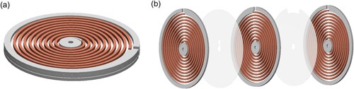
Material extrusion allows the monolithic fabrication of multi-material hardware in a fast, precise and inexpensive manner. However, its layer-by-layer manufacturing fashion introduces certain design limitations. Namely, (i) the geometry of the objects must be such that the sequenced deposition of layers on top of each other is possible, (ii) cavities and overhanging geometries often entail fabrication complexity, (iii) the minimum in-plane feature size that can be fabricated is about the diameter of the nozzle of the printer and (iv) the minimum out-of-plane feature size, or layer height, is determined by the ability of the printer to deposit thin layers, which can be impacted when using feedstock with a filler, e.g. microparticles. With these limitations in mind, a design consisting of stacked conductive spirals with alternating spin, separated by thin insulation films, was deemed best (). This design maximises in-plane conductive loop density while avoiding sharp turns.
Figure 1. Model of 3D-printed stacked solenoid: (a) three-dimensional rendering and (b) exploded view, showing the alternation of conductive spirals and insulation layers.
The dimensions of the solenoids were defined seeking a balance between compactness (which translates into both a smaller size and a denser magnetic flux) and printability (which enforces a minimum feature size). In terms of the performance of the devices, the non-negligible electrical resistivity of the material used to fabricate the conductive path also limits the downscaling that can be implemented. The dimensions chosen to implement the solenoids reported in this study are summarised in .
Table 1. Summary of geometrical dimensions used in the 3D-printed solenoids reported in this study.
3. Materials and methods
3.1. Manufacturing technology
The 3D-printed soft-cored inductors explored in this study were manufactured via material extrusion – a 3D printing technique that produces parts by pushing feedstock through a hot nozzle and depositing it layer by layer, building objects from the ground up. The movement of the nozzle and output rate of the material are controlled according to a G-code file generated by a slicer software based on a computer-aided design (CAD) file. Unlike most AM methods, extrusion is capable of monolithically 3D printing multi-material parts, with recent reports demonstrating the successful fabrication of complex multi-material devices, e.g. grippers for soft robotics [Citation39], vacuum pumps [Citation6], miniaturised, bioprinted structures [Citation42]. Furthermore, extrusion 3D printers are among the most accessible AM systems, making the work developed with them readily reproducible and applicable.
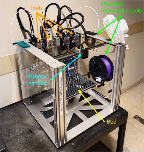
The 3D printer employed in this study is an E3D Motion System and ToolChanger (E3D-Online, Chalgrove, Oxfordshire, UK). The ToolChanger consists of a robotic handler and up to four different tools that can be picked up and used sequentially during a single print job (). This versatile system allows the accommodation of several kinds of tools, including different types of extruders. For this work, the ToolChanger was equipped with three direct-drive filament extruders with 0.4 mm diameter nozzles and one pellet extruder with 0.8 mm diameter nozzle. In direct-drive filament extruders, the motor that pulls the filament is located next to the extrusion nozzle, so that the distance that the filament traverses between the driving gear and the nozzle is minimised. This configuration is advantageous when printing with flexible, soft, or notably heat-sensitive materials to ensure the proper flow of feedstock out of the nozzle. Pellet extruders rely on an Archimedes screw to push a stream of small pieces of feedstock through a hot nozzle; this technique enables the use of non-conventional materials that are not easily formed into 3D printing-compatible filament, such as highly doped, functional materials. Each extruder was dedicated to processing a specific feedstock (i.e. dielectric, conductive or soft magnetic). Using dedicated extruders helps prevent cross-contamination, which can affect the physical properties of the printed materials. Appendix A details the customisation carried out on the printer to overcome reliability issues and to introduce the pellets extruder in the system, which by default consists exclusively of filament extruders.
Figure 2. E3D ToolChanger 3D printer used in this study. The frame of the printer is about 22 in. wide and deep.
The slicer and CAD software used were, respectively, Simplify3D (Simplify3D, Cincinnati, OH USA) and SolidWorks (Dassault Systèmes, Vélizy-Villacoublay, France).
3.2. Materials
The 3D-printed solenoids consist of three materials: a dielectric material provides structural support and insulation, a conductive material makes up the electrical path of the coil, and a soft magnetic material conforms the magnetic core that concentrates the magnetic field generated by the solenoid. The dielectric and conductive materials are both polylactic acid (PLA)-based, while two different soft magnetic materials are explored and compared in this study: iron-filled PLA, and FeSiAl-doped nylon 12. summarises the properties relevant to this work of the printable materials used in this study. Appendix B presents an exhaustive characterisation of the precision and accuracy of the 3D printing setup for each of the materials.
Table 2. Summary of electrical and magnetic properties of the materials used in this study.
3.2.1. Dielectric material
3D-Fuel Pro PLA + (3DomFuel, Inc., Fargo, ND USA) was used as dielectric feedstock to fabricate the support and insulation structures of the soft-cored solenoids (i.e. insulation thin films between conductive layers). To maximise device compactness, the insulation layers were projected to be as thin as possible. After optimisation of the printing process (detailed in Appendix C), it was possible to reliably 3D print 25 µm-thick dielectric layers on top of a discontinuous surface consisting of alternating traces of 3D-printed conductive PLA and air gaps. By stacking two of such thin layers, consistent 50 µm-thick, void-free insulation films were reliably 3D printed.
3.2.2. Conductive material
Electrifi (Multi3D, Middlesex, NC, USA) was used as conductive feedstock to 3D print the spirals that make up the conductive path of the soft magnetic-cored solenoids. Electrifi is a copper microparticle-doped PLA filament with a resistivity of the order of 10 mΩ·cm [Citation10]. To the best of our knowledge, Electrifi is the most electrically conductive filament that is commercially available. Tests were conducted to determine the optimal printing conditions that yielded the highest conductivity of 3D-printed traces in our 3D printing environment. It was found that, for thin traces (width of the order of 600 µm), the optimal printing temperature was around 165°C. Moreover, it was established that, for a fixed trace geometry, printing thicker (and fewer) layers resulted in an improved conductivity over thinner, more numerous layers stacked on top of each other. It was empirically determined that the maximum working temperature of the material is about 60°C; surpassing this temperature results in a significant increase in electrical resistivity.
Besides the challenges described in Appendix C that mainly affect precise, dielectric-conductive bi-material printing, other printing difficulties were encountered while working with conductive PLA:
Due to its high malleability, the Electrifi filament is susceptible to being deformed by the driving gear that pushes it towards the nozzle. When the filament is deformed, the gear cannot push it through the nozzle and the printing operation fails. The deformed filament then must be pulled out, cut and reinserted before resuming printing. The ToolChanger system implements a sensitive mechanism to adjust the pressure that the extruding gear exerts on the filament. Fine adjustments on this mechanism, together with active cooling of the toolhead and filament feed through additional ventilation, were key to reduce the frequency of this jamming issue.
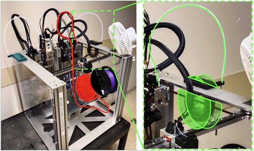
The surface roughness of the raw conductive filament is large. In the ToolChanger system, by design, filament spools are placed far away from the toolheads, so the Electrifi filament traverses a long and meandering path to reach the extruder. This results in high friction, which opposes the pulling force of the direct drive gear, often getting the filament stuck. To solve this issue, a custom spool holder was 3D printed and placed much closer to the extruder head to make the path of the filament from the spool to the extruder shorter and straighter ().
Figure 3. Original (left, in red) versus custom (right, in green) placing of conductive filament spool in the ToolChanger system. The frame of the printer is about 22 in. wide and deep.
3.2.3. Soft magnetic material
Two different soft magnetic materials were explored in this study: iron-filled PLA and FeSiAl-doped nylon 12. Neither exhibits bulk electrical conductivity, which drastically reduces the possibility of the devices suffering from eddy current-induced losses or significant core internal heating. Details of each material are provided below.
3.2.3.1. Soft magnetic PLA
Iron-filled metal composite PLA (Protoplant, Inc., Vancouver, WA, USA) was used in a previous study [Citation41] as soft magnetic filament to monolithically 3D print embedded soft magnetic cores at the centre of 3D-printed solenoids. In this study, the material is used for reference. According to the vendor, its relative magnetic permeability ranges between 5 and 8. The 3D printing of iron-filled PLA encountered the same friction issues described for Electrifi; therefore, its spool was also moved closer to the extruder head in a similar fashion to what was described in Section 3.2.2.
3.2.3.2. Soft magnetic nylon
Producing 3D printing-compatible filament from highly doped materials is challenging [Citation7]. This circumstance limits the ability to shape into a printable filament high-performance, functional materials (e.g. materials with high magnetic permeability). However, it is possible to 3D print directly from feedstock in the form of pellets (i.e. millimetre-scale, Tic Tac-shaped chunks of material). Printing from pellets allows to widen the spectrum of materials that can be used in 3D-printing, as it enables access to industry-grade materials meant for use in traditional manufacturing processes (e.g. injection moulding) that exhibit improved functional properties compared to 3D-printing-compatible filament feedstock [Citation43,Citation44]. The soft magnetic pellets used in this work are made of nylon 12 doped with anisotropic FeSiAl powder in a 50% concentration per volume, equivalent to an 86% concentration per weight (MATE Co., Okayama, Japan). The relative magnetic permeability of this material, as reported by the manufacturer, is equal to 44 when the particles are not mechanically oriented during fabrication (which is the case of this study).
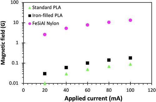
To characterise the ability of each soft magnetic material to concentrate magnetic flux, C-shaped cores were 3D printed in iron-filled PLA, FeSiAl-doped nylon and standard PLA (i.e. nonmagnetic – for reference) (). Enamelled wires were wound around the C-shaped cores and the magnetic field in the gap was measured using a gaussmeter (HGM0900; MAGSYS magnet systeme GmbH, Dortmud, Germany), while applying DC currents. The core printed in iron-filled PLA was found to introduce a twofold increase in the magnetic field measured inside the gap, while the FeSiAl-doped Nylon introduced a 150 multiplication factor, both compared to the field measured inside the gap of the dielectric PLA core ().
Figure 4. C-shaped cores 3D printed in dielectric PLA (left), iron-filled PLA (centre), and FeSiAl-doped Nylon (right) next to a US quarter.
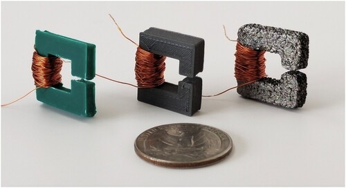
Figure 5. Semi-log plot of magnetic flux inside gap of C-shaped cores printed in dielectric PLA (green), iron-filled PLA (black) and FeSiAl-doped nylon (pink) versus coil current.
3.3. Device fabrication
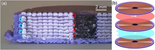
The coils of the solenoids presented in this study are manufactured through the alternated deposition of dielectric thin films and conductive spirals. Electric connection from one spiral to the next is obtained by introducing discontinuities in the insulation layers that alternate from the innermost to the outermost loops, creating a single, long, three-dimensional conductive path that makes the current spin consistently across the device (). The addition of a soft magnetic core at the centre of the solenoids is also compatible with monolithic 3D printing. Electrical contact to the solenoids was achieved using silver conductive epoxy (MG Chemicals 8331D, MG Chemicals Ltd., Burlington, Ontario, Canada).
Figure 6. Close-up, cut view of a 3D-printed inductor showing the inter-layer electrical connections (a) and exploded diagram depicting the different geometries of the insulation layers (b). The alternation of insulation layer geometries results in the formation of electrical connections at the innermost loops (marked in red) and outermost loops (marked in blue), alternatively.
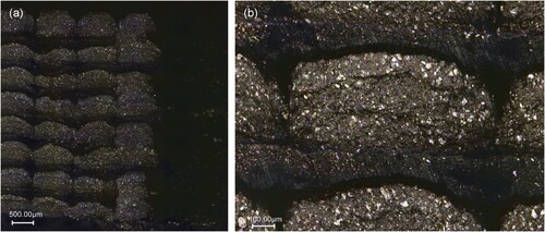
Previous work on solenoids 3D printed via material extrusion reported air-cored devices designed with 0.92 conductive layer linear density (i.e. the devices alternate 600 µm-thick conductive layers and 50 µm-thick insulation films) [Citation40], and iron PLA-cored devices designed with 0.75 conductive layer linear density (i.e. the devices alternate 600 µm-thick conductive layers and 200 µm-thick insulation films) [Citation41]. After overcoming the sources of unreliability of the ToolChanger (Appendix A), this work reports the successful fabrication of cored solenoids designed with 0.92 conductive layer linear density (i.e. 600 µm-thick conductive layers reliably separated by 50 µm-thick insulation films) (). shows microscopic images of the cross-section of the 3D-printed cored solenoids, depicting reliable layer-to-layer insulation. The pictures reveal that the dielectric insulation layers are thicker than they are designed to be, surpassing 100 µm in some areas. This is due to the over-extrusion required to guarantee the deposition of a continuous film on top of a discontinuous substrate. The images also appear to show lateral loop-to-loop contact within the same layer. This is attributed to the deformation of the coil during the cutting procedure and to the high malleability of the conductive material. Loop-to-loop contact was not observed during the supervised fabrication of the devices. Despite the excess thickness of the insulation layers, the macroscopic form factor is preserved, and with it, the compactness of the devices. As discussed in Section 5, the combination of defining reliable thin insulation layers and adding soft magnetic cores, together with the introduction of new printable materials, enables a significant leap in performance with respect to previously reported work.
Figure 7. Three-dimensional, monolithically 3D-printed FeSiAl Nylon-cored eight-layered solenoid: (a) top view next to a US quarter and (b) cut view on top of a US quarter.
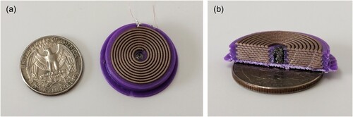
Figure 8. Laser scanning confocal microscope (Keyence VK-X, Keyence, Itasca, IL USA) images of the cross-section of a 3D-printed solenoid: (a) close-up of the inner-most loops showing detail of the inter-layer connections and (b) close-up on the cross-section of a conductive trace showing detail of the dielectric-conductive interface.
The printing settings used to fabricate the solenoids were optimised via experiments, while addressing three main challenges: (i) guaranteeing the consistent deposition of the insulation films that separate adjacent conductive spirals, (ii) achieving electrical conductivity across the whole metal-doped trace and (iii) ensuring the proper flow of particle-doped feedstock through the printer nozzles (i.e. conductive and soft magnetic materials). The values assigned to the key printing parameters are summarised in . The sizes of the nozzles used in this study were selected with the aim of fabricating the most compact devices possible while minimising clogging issues. The PLA-based materials were printed with 0.4 mm nozzles, which are the smallest nozzles shown to reliably print these materials as smaller diameter nozzles can easily clog [Citation9]. The soft magnetic nylon was printed with 0.8 mm diameter nozzles because the size of the filler is significantly larger than in the PLA-based materials (up to 150 µm).
Table 3. Summary of key 3D printing parameters.
In addition to monolithically 3D printing the solenoids, a two-step approach to fabricating the cored solenoids was also explored to yield manufacturing devices with cores that are smoother and have less porosity: first, air-cored solenoids were monolithically 3D printed, leaving the core space empty, and second, a core extruded from the same FeSiAl nylon pellets was inserted in the central cavity to act as core (). The bars were extruded using a Filabot EX2 filament extruder (Filabot Corporation, Barre VT, USA) equipped with a 2.0-mm nozzle.
Figure 9. Fabrication process of 3D-printed solenoid with inserted, 3D-printed core. The diameter of the base of the 3D-printed solenoid is 30 mm.
4. Results
The magnetic field generation of the 3D-printed, cored solenoids was characterised using a home-built setup consisting of an axial gaussmeter (HGM0900; MAGSYS magnet systeme GmbH, Dortmud, Germany), a source-meter power supply (Keithley 2657A; Tektronix, Inc., Beaverton, OR, USA), a nonmagnetic positioning stage (Altos Photonics, Inc., Bozeman, MT, USA), a Mu-metal magnetic shielding chamber (Magnetic Shield Corporation, Bensenville, IL, USA), and a custom 3D-printed support structure fabricated in undoped PLA. The magnetic fields were measured approximately half a millimetre away from the centre of the top conductive layer of the solenoids while applying a DC current ().
Figure 10. Magnetic field @ 0.5 mm from coil top versus current for air-cored ten-layered (black markers, PowerMEMS 2022) [Citation40], iron PLA-cored eight-layered (green markers, CPEEE 2023) [Citation41], and FeSiAl Nylon-cored eight-layered (pink markers, this work), fully 3D-printed solenoids.
![Figure 10. Magnetic field @ 0.5 mm from coil top versus current for air-cored ten-layered (black markers, PowerMEMS 2022) [Citation40], iron PLA-cored eight-layered (green markers, CPEEE 2023) [Citation41], and FeSiAl Nylon-cored eight-layered (pink markers, this work), fully 3D-printed solenoids.](/cms/asset/4688b423-e021-4b92-9dfa-fb1deaf8db72/nvpp_a_2310046_f0010_oc.jpg)
5. Discussion
5.1. Magnetic field strength
As shown in , the solenoids reported in this work produce magnetic fields almost three times larger than those reported before for 3D-printed coils. This improvement is due to three factors: (i) the use of a soft magnetic material with higher magnetic permeability, (ii) the success in printing thin insulation films on a four-extruder 3D printer and (iii) the ability of the 3D-printed conductive trace to withstand higher currents. The first two factors are consequence of the enhancement of the multi-material 3D-printing process and its reliability, achieved through the customisation of the E3D ToolChanger system (Appendix A), while the third factor results from improvements in the design of the insulation and support structure of the cored solenoids, which affect the continuity of the 3D-printed conductive trace. summarises the performance improvement attributable to the change of magnetic core material. The introduction of a soft magnetic PLA core results in an increase in the generated magnetic field by approximately 6%; similarly, the addition of a soft magnetic nylon core, monolithically or in two printing steps, increases the generatable magnetic fields by 25% and 78%, respectively, compared to air-cored solenoids. Two-step fabrication of soft magnetic PLA-cored solenoids was tested and found to yield the same performance as their monolithic fabrication. All the solenoids used to produce the data shown in have the same geometry (600 µm-high conductive traces and 50 µm-thick insulation layers, and eight stacked layers), making the core material the only difference among them. Although the achieved performance is still far from that of traditionally manufactured electromagnets (i.e. fabricated by winding an enamelled wire around a magnetic core), the proof-of-concept solenoids demonstrate the aptitude of material extrusion to create 3D-printed cored solenoids, and highlight the possibility of boosting their performance through improvements in the electrical and magnetic properties of the materials. With such improvements, the proposed solenoids could be monolithically integrated in larger, fully 3D printed devices comprising other functional materials (e.g. flexible materials), enabling the monolithic fabrication of complex hardware, such as pumps and electric motors.
Figure 11. Magnetic field measurements (markers) and fitted line (dashed line) @ 0.5 mm from coil top versus current for air-cored (blue, PowerMEMS 2022) [Citation40], iron PLA-cored (green), and FeSiAl nylon-cored (pink and red), fully 3D-printed solenoids. All the solenoids used for this comparison have the same geometry and differ only in the core material.
![Figure 11. Magnetic field measurements (markers) and fitted line (dashed line) @ 0.5 mm from coil top versus current for air-cored (blue, PowerMEMS 2022) [Citation40], iron PLA-cored (green), and FeSiAl nylon-cored (pink and red), fully 3D-printed solenoids. All the solenoids used for this comparison have the same geometry and differ only in the core material.](/cms/asset/22246e64-f105-4822-a757-0f4ef68a1509/nvpp_a_2310046_f0011_oc.jpg)
5.2. Solenoid size
The magnetic field measurements shown in correspond to coils with 8 (this work), 10 (PowerMEMS 2022 [Citation40]) and 8 (CPEEE 2023 [Citation41]) stacked conductive spirals (). The solenoids presented in this study perform significantly better than their PowerMEMS 2022 predecessors despite having less conductive layers, and they are smaller than their CPEEE 2023 analogues thanks to having thinner insulation films. Specifically, the reported devices are 33% smaller and can carry twice the current compared to the literature. These differences result in boosted performance with smaller device size.
Figure 12. Fully 3D-printed solenoids (left to right): air-cored, ten stacked conductive layers (PowerMEMS 2022[Citation40]), iron PLA-cored, eight stacked conductive layers (CPEEE 2023 [Citation41]), and FeSiAl Nylon-cored, eight stacked conductive layers (this work). The PowerMEMS solenoid (left hand side) has a larger dielectric base that was not considered for size comparison. The diameter of the base of the 3D printed solenoids is equal to 30 mm.
![Figure 12. Fully 3D-printed solenoids (left to right): air-cored, ten stacked conductive layers (PowerMEMS 2022[Citation40]), iron PLA-cored, eight stacked conductive layers (CPEEE 2023 [Citation41]), and FeSiAl Nylon-cored, eight stacked conductive layers (this work). The PowerMEMS solenoid (left hand side) has a larger dielectric base that was not considered for size comparison. The diameter of the base of the 3D printed solenoids is equal to 30 mm.](/cms/asset/99a7631a-d083-45d3-9878-071d997aec78/nvpp_a_2310046_f0012_oc.jpg)
As a result of the non-negligible electrical resistivity of conductive PLA, the size of 3D-printed solenoids can be optimised in terms of the number of conductive loops and stacked layers they comprise. The optimal sizes that yield the strongest magnetic fields are defined by the relationship between the maximum applicable current, the maximum suppliable voltage, and the total resistance of the solenoids [Citation40]. In this work, currents of up to 60 mA and voltages of up to 200 V were reliably applied to the 3D-printed solenoids, yielding the relation of optimal sizes shown in . The values of the maximum magnetic fields generated by the device correspond to the FeSiAl nylon-cored, two-step fabricated solenoids, and are computed by applying a 1.75 multiplication factor (determined experimentally) to the values computed for air-cored solenoids.
Figure 13. Maximum magnetic field as a function of 3D-printed coil dimensions, with maximum current and bias voltage limited to 60 mA and 200 V, respectively, for two-step fabricated, FeSiAl-doped, nylon-cored solenoids.
5.3. Cost of 3D printing hardware
The 3D printing system used in this study, consisting of the E3D ToolChanger system and the Mahor v4 pellet extruder, has a total cost under $4000 (October of 2023), making it a reasonably affordable and accessible option for academic institutions, startups and individuals. As a result, all work described in this study is readily reproducible and applicable.
5.4. Monolithic manufacturability of 3D-printed electromagnets
The results displayed in show that the two-step fabrication of the nylon-cored solenoids yields significantly higher performance than their monolithic fabrication. We believe this is attributed to two causes: (i) the size of the FeSiAl particles present in the soft magnetic material, of up to 150 µm in length, causes the 3D-printed core to have an irregular finish, also noticeable in , which results in a less efficient magnetic flux concentration and (ii) the temperature of the 3D-printed core during the manufacture of the devices is not sufficient for its subsequent layers to bond to each other, which results in the fabrication of an inconsistent, non-solid core. The main cause of this is the rapid cooling of the 3D-printed layers before the next one is deposited on top, resulting in a lack of bonding between layers. It might be possible to address this issue by placing the printer inside an enclosure with temperature regulation or with limited ventilation (so the heat of the printer itself warms up the inside of the enclosure). However, the conductive PLA requires expedited cooling to guarantee successful printing. Hence, material compatibility becomes nontrivial. Possible solutions include: (i) rising the extrusion temperature of the core material; (ii) the combined use of an enclosure and a conductive PLA pellet extruder to overcome the temperature-induced jamming of the filament extruder or (iii) the implementation of dynamic temperature regulation in the whole environment of the 3D printer, or in sections of it (e.g. top layer of print, conductive PLA filament feed). The implementation of one or several of these solutions has the potential to improve the performance of the monolithically fabricated solenoids. However, it is expected that their performance will not surpass that of the two-step fabricated solenoids.
Material incompatibility can also impact the mechanical properties of the finished composite parts [Citation38]. In this work, lack of affinity among materials manifested when combining PLA-based materials (dielectric and conductive) with nylon-based ones (soft magnetic). To compensate for the low adherence between 3D-printed nylon and PLA, the PLA structure was designed to surround the soft magnetic core, holding it in place mechanically. The dielectric and conductive materials (both PLA-based) did not exhibit incompatibility issues during the printing and normal handling and operation of the solenoids.
5.5. Applications
The maximum magnetic fields generated by the inductors reported in this study are of the order of a few Gauss; although the devices attain three times the magnetic fields previously reported from a 3D-printed coil, the magnitude of the magnetic field is still low. For comparison, the magnetic field of the Earth measured at its surface is of the order of 0.5 Gauss, and the strength of a typical refrigerator magnet is about 50 Gauss. This result seemingly limits the foreseeable applicability of fully 3D-printed solenoids in their current state. However, the already-demonstrated technology can allow the fabrication of compact sensors and actuators. For example, it is possible to use the reported 3D-printed solenoids as induction sensors ( and ). In this application, the presence of a soft magnetic core does not introduce a significant difference in the magnitude of the signal generated by the sensor ().
Figure 14. Experimental setup of magnetic induction experiment. The permanent magnets used in this magnetic sensor demonstration are N42 neodymium magnets (K&J Magnetics, Inc., Pipersville, PA, USA).
Figure 15. Extract of magnetic induction experiment measurements: voltage across an 8-layered 3D-printed solenoid without (blue) and with (red) an inserted FeSiAl nylon core, when spinning the permanent magnets at different speeds (DC motor biased at 6V – dashed lines, and 12V – solid lines) The voltage data is averaged over 10 samples to filter out noise.
Additionally, it might also be possible to monolithically fabricate thin-membrane actuators by taking further advantage of multi-material extrusion 3D printing to include flexible materials in the 3D-printed devices. Moreover, it might be possible to use other 3D printing technologies, e.g. microplasmas [Citation45,Citation46] to print other electronic components on the surfaces of the 3D-printed solenoids and implement more complex circuits.
6. Conclusion
This work reported fully 3D-printed, cored solenoids with a threefold performance improvement over previously reported additively manufactured coils. The scalable, three-material solenoids are fabricated via material extrusion – one of the most versatile and democratised 3D printing technologies. The performance increase is achieved through the use of a soft magnetic material with high magnetic permeability, enabled by the integration of a pellet extruder into a commercially available, highly customisable, multi-material 3D printing system. The magnetic fields generated by the devices are Gauss level and experience a 78% gain when including a 3D-printed soft magnetic core compared to air-cored coils. The fully 3D-printed solenoids can be readily used as induction sensors. Improvements in material properties (e.g. electrical conductivity, magnetic permeability) and manufacturing capabilities (e.g. minimum feature size) can further boost the performance of these devices and enable the monolithic, inexpensive fabrication of custom magnetic sensors and actuators (e.g. pumps, electric motors). Further progress in the monolithic manufacture of 3D-printed electronics can enable the fabrication of functional, complex hardware (e.g. motorised prostheses, miniature spacecraft) right off the printer bed. This technology is of particular interest for low-cost, low-waste manufacturing of integrated devices and highly customised hardware in remote areas with limited access to resources and manufacturing equipment (e.g. in-space manufacturing).
Acknowledgements
The authors would like to thank MATE Co., Okayama, Japan, for providing the FeSiAl-doped nylon pellets for fabricating some of the soft magnetic-cored inductors, and Tumaker, Irun, Spain, for 3D printing the C cores in FeSiAl-doped nylon 12.
Disclosure statement
No potential conflict of interest was reported by the author(s).
Data availability
The data that support the findings of this study are available at https://doi.org/10.7910/DVN/XXYAEI.
Additional information
Funding
References
- Quanjin M, Rejab MRM, Idris MS, et al. Recent 3D and 4D intelligent printing technologies: a comparative review and future perspective. Procedia Comput Sci. 2020;167:1210–1219. doi:10.1016/j.procs.2020.03.434.
- Melo Máximo D, Velásquez-García LF. Additively manufactured electrohydrodynamic ionic liquid pure-ion sources for nanosatellite propulsion. Addit Manuf. 2020;36:101719. doi:10.1016/j.addma.2020.101719.
- Izquierdo-Reyes J, Bigelow Z, Lubinsky NK, et al. Compact retarding potential analyzers enabled by glass-ceramic vat polymerization for CubeSat and laboratory plasma diagnostics. Addit Manuf. 2022;58:103034. doi:10.1016/j.addma.2022.103034.
- Li F, Macdonald NP, Guijt RM, et al. Increasing the functionalities of 3D printed microchemical devices by single material, multi material, and print-pause-print 3D printing. Lab Chip. 2019;19:35–49. doi:10.1039/C8LC00826D
- Taylor AP, Velásquez-García LF. Miniaturized diaphragm vacuum pump by multi-material additive manufacturing. J Microelectromech Syst. 2017;26(6):1316–1326. doi:10.1109/JMEMS.2017.2743020
- Lee H-J, Cañada J, Velásquez-García LF. Compact peristaltic vacuum pumps via multi-material extrusion. Addit Manuf. 2023;68:103511. doi:10.1016/j.addma.2023.103511
- Taylor AP, Vélez Cuervo C, Arnold D, et al. Fully 3D-printed, monolithic, mini magnetic actuators for low-cost, compact systems. J Microelectromech Syst. 2019;28(3):481–493. doi:10.1109/JMEMS.2019.2910215
- Taylor AP, Izquierdo Reyes J, Velásquez-García LF. Compact, magnetically actuated, additively manufactured pumps for liquids and gases. J Phys. D Appl Phys. 2020;53(35):355002. doi:10.1088/1361-6463/ab8de8
- Sun Z, Velásquez-García LF. Monolithic FFF printed, biodegradable, biocompatible, dielectric–conductive microsystems. J Microelectromech Syst. 2017;26(6):1356–1370. doi:10.1109/JMEMS.2017.2746627
- Flowers PF, Reyes C, Ye S, et al. 3D printing electronic components and circuits with conductive thermoplastic filament. Addit Manuf. 2017;18:156–163. doi:10.1016/j.addma.2017.10.002.
- Colella R, Catarinucci L. Wearable UHF RFID sensor-tag based on customized 3D-printed antenna substrates. IEEE Sensors J. 2018;18(21):8789–8795. doi:10.1109/JSEN.2018.2867597
- Su W, et al. 3D printed wearable flexible SIW and microfluidics sensors for Internet of Things and smart health applications. In: 2017 IEEE MTT-S International Microwave Symposium (IMS), Honololu, HI, USA; 2017. p. 544–547. doi:10.1109/MWSYM.2017.8058621.
- Njogu P, Sanz-Izquierdo B, Elibiary A, et al. 3D printed fingernail antennas for 5G applications. IEEE Access. 2020;8:228711–228719. doi:10.1109/ACCESS.2020.3043045
- Bito J, Bahr R, Hester JG, et al. A novel solar and electromagnetic energy harvesting system with a 3-D printed package for energy efficient Internet-of-Things wireless sensors. IEEE Trans Microwave Theory Tech. 2017;65(5):1831–1842. doi:10.1109/TMTT.2017.2660487
- Savvides G, et al. 3D rapid-prototyped 21-31-GHz hollow SIWs for low-cost 5G IoT and robotic applications. IEEE Access. 2021;9:11750–11760. doi:10.1109/ACCESS.2021.3051180.
- Dahle R, Rasel R. 3-D printing as an effective educational tool for MEMS design and fabrication. IEEE Trans Educ. 2016;59(3):210–215. doi:10.1109/TE.2016.2515071
- Sun Y, Li Q. The application of 3D printing in mathematics education. In: 2017 12th International Conference on Computer Science and Education (ICCSE), Houston, TX, USA; 2017. p. 47–50. doi:10.1109/ICCSE.2017.8085461.
- Kornbluth Y, Mathews RH, Parameswaran L, et al. Fully 3D-printed, ultrathin capacitors via multi-material microsputtering. Adv Mater Technol. 2022;7(8):2200097. doi:10.1002/admt.202200097.
- Khan Z, He H, Chen X, et al. Dipole antennas 3D-printed from conductive thermoplastic filament. In: 2020 IEEE 8th Electronics System-Integration Technology Conference (ESTC), Tønsberg, Norway; 2020. p. 1–4. doi:10.1109/ESTC48849.2020.9229736.
- Perales IA, Velásquez-García LF. Fully 3D-printed carbon nanotube field emission electron sources with in-plane gate electrode. Nanotechnology. 2019;30(49):495302. doi:10.1088/1361-6528/ab3d17
- Ntagios M, Escobedo P, Dahiya R. 3D printed robotic hand with embedded touch sensors. In: 2020 IEEE International Conference on Flexible and Printable Sensors and Systems (FLEPS), Manchester, UK; 2020. p. 1–4. doi:10.1109/FLEPS49123.2020.9239587.
- Chirila R, Ozioko O, Schyns PG, et al. Multidirectional strain sensor using multimaterial 3D printing. In: 2022 IEEE International Conference on Flexible and Printable Sensors and Systems (FLEPS), Vienna, Austria; 2022. p. 1–4. doi:10.1109/FLEPS53764.2022.9781529.
- Persad J, Rocke S. “Multi-material 3D printed electronic assemblies: A review. Results Eng. 2022;16:100730. ISSN 2590-1230. doi:10.1016/j.rineng.2022.100730.
- Goh GL, Zhang H, Chong TH, et al. 3D printing of multilayered and multimaterial electronics: a review. Adv Electron Mater. 2021;7:2100445. doi:10.1002/aelm.202100445
- Hensleigh R, Cui H, Xu Z, et al. Charge-programmed three-dimensional printing for multi-material electronic devices. Nat Electron. 2020;3:216–224. doi:10.1038/s41928-020-0391-2
- Muscat A, Bhattacharya S, Zhu Y. Electromagnetic vibrational energy harvesters: a review. Sensors. 5555;22(15):2022. doi:10.3390/s22155555
- Miyajima H, et al. A MEMS electromagnetic optical scanner for a commercial confocal laser scanning microscope. J Microelectromech. Syst. 2003;12(3):243–251. doi:10.1109/JMEMS.2003.809961.
- Getpreecharsawas J, Puchades I, Hournbuckle B, et al. An electromagnetic MEMS actuator for micropumps. In: Proc. 2nd Int. Conf. on Perspective Technologies and Methods in MEMS Design; 2006. p. 11–14. doi:10.1109/MEMSTECH.2006.288652.
- Choi Y-S, Yoon J-B, Kim B-I, et al. A high-performance MEMS transformer for silicon RF ICS. In: Technical Digest Fifteenth IEEE Int. Conf. on Micro Electro Mechanical Systems (Cat. No.02CH37266); 2002. p. 653–656. doi:10.1109/MEMSYS.2002.984355.
- Lei C, Zhou Y, Gao X, et al. Fabrication of a solenoid-type inductor with Fe-based soft magnetic core. J Magn Magn Mater. 2007;308(2):284–288. doi:10.1016/j.jmmm.2006.06.002.
- Gassend B, Velásquez-García LF, Akinwande AI. Design and fabrication of DRIE-patterned complex needle-like structures. J Microelectromech Syst. 2010;19(3):589–598. doi:10.1109/JMEMS.2010.2042680
- Velásquez-García LF, Cheung K, Akinwande AI. An application of 3D MEMS packaging: out-of-plane quadrupole mass filters. J Microelectromech. Syst. 2008;16(6):1430–1438. doi:10.1109/JMEMS.2008.2006769
- Velásquez-García LF, Akinwande AI, Martínez-Sánchez M. Precision hand assembly of MEMS subsystems using DRIE-patterned deflection spring structures: an example of an out-of-plane substrate assembly. J Microelectromech Syst. 2007;16(3):598–612. doi:10.1109/JMEMS.2007.892931
- Heubel EV, Velásquez-García LF. Microfabricated retarding potential analyzers with enforced aperture alignment for improved ion energy measurements in plasmas. J Microelectromech Syst. 2015;24(5):1355–1369. doi:10.1109/JMEMS.2015.2399373
- Zhou N, Liu C, Lewis JA, et al. Gigahertz electromagnetic structures via direct ink writing for radio-frequency oscillator and transmitter applications. Adv Mater. 2017;29:1605198. doi:10.1002/adma.201605198
- Gu Y, Park D, Bowen D, et al. Direct-write printed, solid-core solenoid inductors with commercially relevant inductances. Adv Mater Technol. 2019;4:1800312. doi:10.1002/admt.201800312
- Loh G, Pei E, Gonzalez-Gutierrez J, et al. An overview of material extrusion troubleshooting. Appl Sci. 2020. 10.4776.10.3390app10144776.
- Lopes LR, Silva AF, Carneiro OS. Multi-material 3D printing: The relevance of materials affinity on the boundary interface performance. Addit Manuf. 2018;23:45–52. ISSN 2214-8604. doi:10.1016/j.addma.2018.06.027.
- Goh G, et al. A 3D printing-enabled artificially innervated smart soft gripper with variable joint stiffness. Adv Mater Technol. 2023: 2301426. doi:10.1002/admt.202301426
- Cañada J, Velásquez-García LF. Fully 3D-printed solenoids for compact systems. In: 21st International Conference on Micro and Nanotechnology for Power Generation and Energy Conversion Applications (PowerMEMS), Salt Lake City, UT, USA; 2022. p. 150–153. doi:10.1109/PowerMEMS56853.2022.10007551.
- Cañada J, Velásquez-García LF. Monolithically 3D-printed, miniature solenoids with soft magnetic core for compact systems. In: 13th International Conference on Power, Energy and Electrical Engineering (CPEEE), Tokyo, Japan; 2023. p. 116–120. doi:10.1109/CPEEE56777.2023.10217558.
- Rocca M, Fragasso A, Liu W, et al. Embedded multimaterial extrusion bioprinting. SLAS Technol. 2018;23(2):154–163. ISSN 2472-6303. doi:10.1177/2472630317742071.
- Li L, Tirado A, Nlebedim I, et al. Big area additive manufacturing of high performance bonded NdFeB magnets. Sci Rep. 2016;6:36212. doi:10.1038/srep36212
- Martin V, et al. Low cost 3D printing of metals using filled polymer pellets. HardwareX. 2022;11:e00292. doi:10.1016/j.ohx.2022.e00292
- Kornbluth Y, Mathews RH, Parameswaran L, et al. Nano-additively manufactured gold thin films with high adhesion and near-bulk electrical resistivity via jet-assisted, nanoparticle-dominated, room-temperature microsputtering. Addit Manuf. 2020;36:101679. doi:10.1016/j.addma.2020.101679
- Kornbluth Y, Mathews RH, Parameswaran L, et al. Room-temperature, atmospheric-pressure deposition of dense, nanostructured metal films via microsputtering. Nanotechnology. 2019;30(28):285602. doi:10.1088/1361-6528/ab1281
Appendix A.
3D printer customization
A.1. Printing reliability
The E3D ToolChanger system is a powerful, yet finicky machine. Its numerous moving parts and alignment-sensitive processes make for a number of potential sources of malfunction. Recurring issues include: (i) failed tool pick-up/drop-off, often resulting in the dropping of a tool towards the bottom of the printer, potentially causing damage to the tool, and (ii) inconsistent homing because of the sensor-less implementation of the homing algorithm that relies on motor stalling. Each issue was addressed as follows:
Failed tool pick-up/drop-off: successful pick-up and drop-off of tools is essential for the fabrication of multi-material parts. Two main causes of tool pick-up/drop-off failure were found:
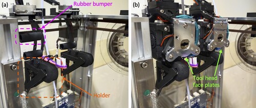
Misalignment of tool and robotic handler during pick-up: the tools are collected by the robotic handler through a pin-slot mechanism: the handler carries a rotating pin that is inserted inside a slot on a specific tool for pick-up. Once the pin is inserted, it rotates to secure the grip on the selected tool. Misalignments smaller than a tenth of a millimeter between the pin and the tool slot were found to be enough to cause this operation to fail. To address this issue, (i) the X-Y position of the docked toolheads was precisely coded into the configuration files of the printer, (ii) the Z alignment was corrected by re-designing and re-printing the structural parts of the printer that hold the tools while docked, the original dimensions of which are given by the manufacturer of the printer, and (iii) rubber bumpers were installed behind each tool to provide a flexible point of contact and make up for pitch misalignments ().
Open-loop hooking mechanism: the rotation of the hooking pin inside the tool slot for tool pick-up/drop-off is performed without any sensing, and hence it can fail, totally or partially, without triggering any alerts. Partial hooking failures are especially common during tool drop-off and result in the robotic handler not releasing the tools before attempting to pick up the next one, causing one tool to slam into the other, or to fall towards the bottom of the printer. To prevent the tools from being dragged out of their docks due to incomplete releases, a support structure was designed, 3D printed, and attached to the printer frame, to hold the tools from underneath and oppose the force of the robotic handler when it moves away from the unhooked tools ().
Inconsistent homing: the E3D ToolChanger relies on motor stalling to find its origin of coordinates. As a result, the homing operation fails occasionally, which can cause the robotic handler to crash into the tools while trying to pick them up. This issue was addressed by supervising the printer during homing, and by repeating the process if it had failed. Reliable, unsupervised homing could be achieved by adding endstop switches on each axis.
Figure A1. Custom features added to the E3D ToolChanger to improve its tool pick-up/drop-off reliability, shown (a) without docked tool, and (b) with docked tool. The total height and body width of the tool head face plates are equal to 65 mm and 40 mm, respectively.
A.2. Pellet extrusion
The default configuration of the E3D ToolChanger system consists of four filament extruders. To print with pellet feedstock, one of the filament extruders needs to be replaced by a pellet extruder. The pellet extruder used in this work is a Mahor v4 pellet extruder (Mahor.xyz, Spain). This extruder was selected as its predecessor, Mahor v3, has previously been successfully integrated into an E3D ToolChanger machine and used to 3D print metallic parts [Citation44]. To adapt the Mahor v4 pellet extruder to the E3D ToolChanger docking system, a custom case was designed and 3D printed. The case wraps around the pellet extruder and provides anchor points for the E3D toolhead plate and docking port, necessary to allow the pick-up/drop-off of the tool (). Similarly, the dock that holds the extruder when inactive was redesigned to accommodate the larger dimensions of the pellet extruder (). The final configuration of the E3D ToolChanger system used in this study consists of three direct drive filament extruders and one pellet extruder (). shows the relation of extruders and materials.
Figure A2. Assembled Mahor v4 pellet extruder with custom 3D-printed parts for E3D ToolChanger compatibility. The total height and body width of the tool pick-up/drop-off face plate are equal to 65 mm and 40 mm, respectively.
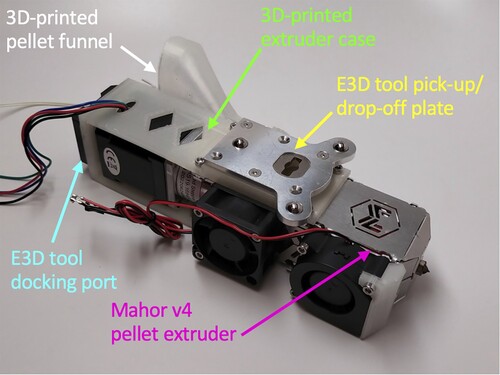
Figure A3. E3D ToolChanger dock adapted to the dimensions of a Mahor v4 pellet extruder. The width of the standard dock is equal to 40 mm.
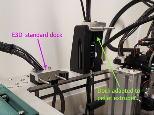
Figure A4. Lineup of three direct drive filament extruders and one Mahor v4 pellet extruder on an E3D ToolChanger. The total height and body width of the tool head face plates are equal to 65 mm and 40 mm, respectively.
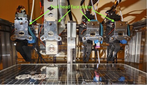
Table A1. Relation of extruders and materials. The labeling of the extruders matches their order from left to right in Figure A5.
Appendix B.
3D printer characterization
The precision and accuracy of the 3D printing setup used in this study were characterized by analyzing the linearity and correspondence between the dimensions of 3D-printed parts and those of their corresponding CAD source files. Pyramid-like structures (, b) were printed with each extruder, in their corresponding material. In these experiments, the step height was set to 200 µm. A laser scanning confocal microscope with nanometer level resolution (Keyence VK-X, Keyence, Itasca, IL USA) was used to perform height scans of the printed samples (). The actual heights and widths of the steps were then extracted from the scans and compared against the CAD-specified dimensions (). For the PLA materials, there is excellent correspondence and linearity between printed and CAD dimensions, with the least-squares slopes close to unity, very small offsets, and correlation coefficients close to unity. The soft magnetic nylon also shows good linearity and correspondence, although a higher variability in the measurements can be appreciated. This is a result of the surface roughness of the 3D-printed parts, attributed to the large particle size of the filler (up to 150 µm). This circumstance also motivated the fabrication of characterization pyramids with wider steps, resulting in a decrease in the count of steps that can be measured within the field of view of the confocal microscope.
Figure B1. Computer-generated rendering (a), 3D-printed samples (b), and 3D reconstruction from confocal microscope data (c), of the pyramid-like structure used for characterizing the 3D-printing setup.
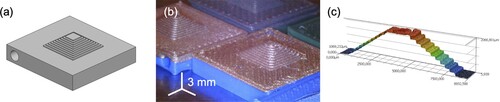
Table B1. Least-squares linear fit of width and height measurements of 3D-printed step pyramids versus CAD-specified dimensions. In the plots AW = actual width, AH = actual height, CW = CAD width, CH = CAD height.
Appendix C.
Printing thin insulation films
Achieving electrical insulation between conductive layers is essential for the fabrication of the proposed stacked solenoids. Insulation films must guarantee that there is no electrical contact between adjacent layers (except where deliberately designed for) while being as thin as possible to keep the device compact and enhance its performance. The standard layer height used by cartesian polymer extrusion 3D printers is in the order of 200 µm, while the resolution of the vertical movement of the printing stage is typically in the order of 1 µm. Leveraging those magnitudes, in this study, it was estimated that a layer height of 25 µm would be the approximate limit of what the utilized 3D printing systems could reliably produce. To test the printability of such thin layers, pyramid-like structures similar to those presented in Appendix B were 3D printed with a MakerGear M3-ID 3D printer (MakerGear LLC, Beachwood, OH USA), and their dimensions were measured with a laser scanning confocal microscope (Keyence VK-X, Keyence, Itasca, IL USA) and compared to the CAD-defined dimensions (). The data show excellent correspondence between the measurements and the CAD dimensions of the lower steps of the pyramids. However, the 3D printer struggled to print the top steps of the characterization pyramids (). This is attributed to two causes: (i) as 25 µm-high layers are stacked on top of each other, small irregularities accumulate and amplify, ultimately reaching a size that interferes with the correct printing of the layers on top, and (ii) as the surface area of the pyramid steps becomes smaller, the traces to be printed become shorter, which reduces their adherence to previous layers and results in printing defects that become fatal when printing thin layers. Despite this issue, the correct deposition of enough 25 µm-high layers to produce a consistent insulation film (two) was realized.
Figure C1. Confocal microscope imaging (a), and 3D reconstruction (b) of the pyramid-like structure used for characterizing the 3D-printing setup with 25 µm layer height.
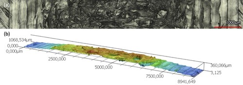
Table C1. Least-squares linear fit of width and height measurements of 3D-printed step pyramids versus CAD-specified dimensions. In the plots AW = actual width, AH = actual height, CW = CAD width, CH = CAD height.
After confirming the feasibility of printing two 25 µm-thick films on top of each other, optimization of the printing process to reliably 3D print them on top of a discontinuous support (i.e., alternating conductive loops and voids between them) was carried out. The key takeaways from the tunning process can be summarized in three ideas: (i) the dielectric PLA material needs to be over-extruded to ensure consistent electrical insulation, (ii) the deposition speed of the dielectric PLA needs to be low, and (iii) the conductive PLA laying directly underneath an insulation layer must be allowed to cool down before printing on top of it to avoid short circuits [Citation40]. The first two issues were addressed at the G-code level, while the third issue was addressed by installing external cooling fans and adding dummy structures to be printed in dielectric PLA while the conductive PLA features cool down and solidify. Dummy structures were also helpful to avoid oozing issues (also called “stringing” in the 3D printing material extrusion literature) and to prevent the deposition of an excess of melted material at the start of each layer. This can happen when an extruder is idle while still hot, causing melted feedstock to accumulate inside the nozzle and come out in bulk at the start of the next layer, altering the geometry of the 3D printed part. This issue is particularly relevant in multi-material extrusion because each extruder can spend a significant amount of time inactive while other tools are at work, and becomes especially critical when 3D printing very thin layers. By starting to print each layer from a dummy structure rather than directly from the desired part, the excess material is deposited on the dummy structure, and not on the part. When the process requires over-extrusion on the part, the geometry of the dummy structure acquires relevance, as a dense dummy structure could become oversized and interfere with the printing process (e.g., the nozzle can collide with an overgrown dummy structure and detach it from the printer bed). In this work, single-wall dummy structures were used to allow lateral overflow of the over-extruded material and prevent the structures from becoming saturated. After optimizing the process, it was possible to reliably 3D print 25 µm-thick dielectric layers on top of a discontinuous surface consisting of alternating traces of 3D-printed conductive PLA and air gaps. Even though this optimization study was carried out using a MakerGear M3-ID 3D printer, the learned lessons were found to be translatable to the E3D ToolChanger working environment.