
ABSTRACT
With the prosperity of laser powder bed fusion (LPBF) technology, post-processing tends to be increasingly attractive in further improving the performance of the LPBFed parts. In this study, post-heat treatment and electroless plating were performed on the LPBFed 316L stainless steel to investigate the evolution of surface topography, mechanical property and corrosion behaviour. The results show that the as-built part features melt tracks and fine cellular substructures, which presents higher deformation resistance than the cast and recrystallized counterparts. The uniform amorphous Ni-P coating can significantly increase microhardness of as-built 316L stainless steel from ∼300 to ∼800 HV. In addition, the as-built parts with/without coatings have better corrosion resistance than the corresponding cast ones, which can be further improved through 450°C annealing. Moreover, the coatings can also prevent the localised corrosion effectively. Therefore, this study provides available post-processing methods for further improve the performance of LPBFed 316L stainless steel.
1. Introduction
Austenitic stainless steel possesses a stable and complete austenite microstructure, outstanding corrosion resistance, as well as favourable mechanical properties, making it extensively applied in modern industries. Laser Powder Bed Fusion (LPBF) is a powder-bed-based additive manufacturing process, which has emerged as one of the most promising techniques for fabricating various metal components [Citation1,Citation2]. This is because it can fabricate nearly fully dense metal parts with complex geometrical structures and high surface quality [Citation3]. Owing to its excellent performance, 316L stainless steel becomes one of the earliest metals applied in the LPBF process. Furthermore, with the continuous improvement of the manufacturing process, Liu et al. [Citation4] found that the LPBF 316L stainless steel has relatively higher mechanical property and hardness than that of the traditionally manufactured counterparts owing to the fine cellular microstructure in the additively manufactured materials. However, there are still some drawbacks in the material fabricated by LPBF, e.g. relatively poor surface mechanical properties, and low wear resistance and hardness [Citation5].
The high corrosion resistance of 316L stainless steel is a key characteristic that has garnered significant research attention in the field, particularly regarding its corrosion behaviour when processed using LPBF technology. Zhao et al. [Citation6] investigated the impact of scanning strategy and building orientation on corrosion behaviour, revealing that the LPBF 316L stainless steel with a top surface fabricated using a 90° rotation scanning strategy exhibited superior corrosion resistance. Revilla et al. [Citation7] compared the corrosion behaviour between LPBF and wrought 316L parts. They found the former had a much wider passivity range. Chen et al. [Citation8] proposed a high-temperature treatment to improve the corrosion resistance of additively manufactured 316L parts. However, these works focused on revealing corrosion differences and how to improve corrosion resistance. For fundamentally inhibiting localised corrosion, there is no related investigation reported. It is known that localised corrosion is a dangerous corrosion type in the application, which may cause severe destructive results without visible corrosion products on the surface as obvious warning signs.
Therefore, surface modification of 316L stainless steel is imperative for ensuring the safety and reliability of its applications. Recently, several researchers have endeavoured to enhance the surface performance of additively manufactured 316L stainless steel components. For example, Tromas et al. [Citation9] successfully modified the surface hardness and elastic modulus by inducing plasma nitriding on 316L stainless steel. Lang et al. [Citation10] improved the yield stress by generating a nanostructural surface layer. Lyu et al. [Citation11] significantly enhanced the surface hardness and wear resistance by depositing TiN/TiAlN coating. Groden et al. [Citation12] reported Inconel 718-CoCrMo bimetallic structures frabricated through directed energy deposition, which presented high temperature oxidation and wear/corrosion resistance. In addition, the LPBF technology enables the selective melting of another powder material to facilitate the preparation of coatings on the substrate [Citation13,Citation14]. Cold spray is also an interesting method to procduce coatings with superior quality and low oxidation [Citation15]. However, there is currently a lack of research on the use of electroless plating to modify LPBF 316L stainless steel in order to enhance its surface mechanical properties and mitigate localised corrosion.
Electroless plating has been widely employed as an effective method for improving surface properties in various industries such as oil, marine, automotive, and chemical processing equipment [Citation16]. Ni-P coating is among the mostly used electroless plating types owing to its high hardness, strength, wear resistance and corrosion resistance. Compared with electroplating, this surface modification method is able to form a more uniform and denser coating on parts without the constraint of a complex structure. Additionally, the properties of electroless coatings can be tailored to meet specific application requirements through adjustments in phosphorus content. Typically, microcrystalline structures are achieved with low levels of phosphorus (<5 wt.% P), while amorphous coatings are formed with high levels (10–13 wt.% P). Medium phosphorus coatings exhibit a mixed microstructure consisting of both crystalline and amorphous phases. With the increase of P content, the coating exhibits improved corrosion resistance in NaCl solution. For example, the Ni–Cu–P coating with high phosphorus content deposited on can improve corrosion resistance [Citation17]. The electroless Ni-P-BN coating is can improve the high-temperature wear resistance of 316L stainless steel [Citation18]. However, for the coatings on the additively manufactured 316L stainless steel, the corresponding research on corrosion behaviour and mechanical properties is lacking.
From the above literature survey, although extensive research has been done on the performance of traditionally manufactured 316L stainless steel with Ni-P coatings, there lack systematic research on the additively manufactured 316L stainless steel with coatings, particularly under different heat treatment conditions. The present study is therefore aimed to investigate the influence of heat treatment of the substrate and subsequent surface modification by depositing Ni-P coating on the comprehensive performance of LPBF 316L stainless steel. The phase composition, microstructure evolution, and mechanical properties of the coated and uncoated samples were analysed first. Then, the performance of coatings on the substrate under different heat treatments was characterised. Finally, a systematic investigation was conducted to analyse the corrosion behaviours of both AM and heat-treated LPBF 316L stainless steel parts with and without coatings. This study will provide a theoretical and technical reference for the manufacturing of high-performance additive-manufacturing 316L stainless steel parts.
2. Materials and methods
2.1. Sample preparation
The samples with a size of 12 × 12 × 15 mm (set as the substrate) were manufactured in EOS M 290 (EOS GmbH) additive manufacturing machine. Optimised process parameters from the supplier are used, which are laser power 195 W, scanning speed 1000 mm/s, layer thickness 20 µm, and hatch distance 90 µm, respectively. The scanning strategy is that the moving direction of the laser beam is rotated by 67.5° per layer. In addition, an argon atmosphere was used in the build chamber to reduce the oxygen content. The material utilised in this investigation is commercial EOS Stainless Steel 316L powders from EOS GmbH (Germany) using an inert-gas-atomized method. The powders are spherical particles with a sieve fraction of 20–50 µm. The chemical compositions of the powder used as feedstock are presented in .
Table 1. Chemical compositions of the 316L stainless steel powder (wt. %).
Heat treatment was carried out on the LPBF 316L samples in an argon atmosphere to investigate the difference in performance between the AM and heat-treated samples. Two heat treatment processes with low and high temperatures are as follows: (1) heat to 450°C, hold for 3 h, and cool to room temperature in the furnace (marked as AM-450) to release residual stress without changing the microstructure; (2) heat to 1100°C, hold on 1 h, and cool to room temperature in the furnace (marked as AM-1100) to homogenise microstructure and eliminate chemical segregation. Then, both AM and heat-treated samples were deposited with Ni-P coatings in the same batch under the same conditions. Before depositing the coating, the large samples were first cut into 12 × 12 × 4 mm sheets by electrical discharge machining. Then, they were ultrasonically cleaned with alcohol to remove contaminants and polished sequentially with #320, #800, #1200 and #2000 sandpapers, as well as 0.3 um alumina suspension. Lastly, the samples were coated by Richport Technology Pte Ltd. using a commercially available process. Firstly, the substrates underwent thorough cleaning and pretreatment with an acid solution. Subsequently, they were immersed in the plating solution for 1.5 h of electroless plating. In this study, the commercial cast 316L stainless steel samples with and without coatings were also investigated as a comparison with the LPBF ones.
2.2. Characterisation
The substrate's microstructure was observed using a JEOL JSM-5500LV scanning electron microscope (SEM), while the chemical content was analysed through energy dispersive x-ray spectroscopy (EDS) equipped in the SEM. The grain morphology, crystallographic orientation, and grain boundaries of the LPBF 316L stainless steel were characterised using an A JSM-7200F scanning electron microscope (SEM) equipped with an EDAX Velocity Super electron backscattered diffraction (EBSD) detector. The experiment was conducted with an accelerating voltage of 25 kV and a scanning step size of 0.5 μm. The raw data obtained from the EBSD test was analysed using Channel 5 software. Mechanical polishing and ionic polishing are subsequently conducted on the samples before EBSD tests. Surface roughness with and without coatings was measured by Olympus LEXT OLS5500 laser confocal microscope (LCM) and three trials were conducted on each sample. The cross-section morphology after etching and the thickness of the coatings were also observed and measured through SEM. The etching process was conducted in dilute aqua regia (HCl: HNO3: H2O = 3:1:6) for 120 s after mechanical polishing. Corrosion morphologies after the potentiodynamic polarisation test were characterised by SEM. The crystal structure of the substrate and coating was evaluated using X-ray diffraction on a LabX XRD-6000 diffractometer (Shimadzu) equipped with monochromatized Cu-Kα radiation (λ = 0.15418 nm). A step size of 0.02° was employed, and diffraction peaks were measured over the range of 2θ from 20° to 120°. The microhardness tests were conducted using an instrumented indentation tester (Anton Paar MCT3) with a maximum applied force of 200 mN, a loading rate of 600 mN/min, and a data acquisition frequency of 100 Hz. The average microhardness was calculated from five measurements. The MCT + UNHT micro scratching tester from CSM Instruments was utilised to conduct the scratching tests. The coating adhesion strength was evaluated in accordance with ASTM C1624-05(2015) [Citation19] using a progressive load scratch test, where the normal force of the indenter increased from 0–30 N at a rate of 30 N/min and an advance rate of 5 mm/min, resulting in a scratch length of 5 mm. Similarly, for the substrate's scratch tests, a comparable test condition was employed with a load range of 0–15 N. The tests are conducted in triplicate to ensure accuracy.
2.3. Electrochemical test
The corrosion behaviour of the examined components was analysed through potentiodynamic polarisation and electrochemical impedance spectroscopy (EIS) tests, followed by a corrosion morphology analysis to elucidate the underlying mechanism. For the substrates, they were polished sequentially with #320, #800, #1200 and #2000 sandpapers, as well as 0.3 um alumina suspension. Both the substrates and coated samples underwent alcohol cleaning followed by drying in a hot air environment prior to electrochemical testing. EIS and potentiodynamic polarisation tests were performed using a three-electrode system controlled by Interface1010E (Gamry Instruments Inc., USA). The counter electrode was made of Pt, the reference electrode was a saturated calomel electrode (SCE), and the workpieces served as the working electrodes in the experiments. The electrochemical cell is F029 (Aida Hengsheng, China) with a 1cm2 hole to expose the sample to the electrolyte solution. The electrolyte was prepared by dissolving reagent grade NaCl in deionised water to obtain a 3.5 wt.% NaCl solution, and the salt bridge was filled with 3 mol/L KCl-agar gel. Potentiodynamic polarisation tests were conducted with a scanning rate of 0.167 mV/s across a potential range of −0.25 V to +1.5 V versus SCE, or until the corrosion current reached 10 mA. The EIS tests were performed with a sinusoidal AC voltage disturbance with an amplitude of 10 mV and a frequency range from 105 to 10−2 Hz. Prior to initiating all tests, the open circuit potential in the electrolyte was monitored over a period of 60 min for stability. All experiments were repeated three times to ensure repeatability.
3. Results and discussion
3.1. Microstructure and surface topography
displays the microstructure of cast and LPBF 316L stainless steel parts under different heat treatments. The LPBF samples are principally free of pores, which is conducive to the conduct of this research. (a, a1) illustrates the characteristic polygonal grain structure of cast 316L stainless steel, while (a2) reveals the presence of inclusions rich in oxygen, manganese, and sulfur within the cast samples, which has been confirmed through EDS analysis. (b) presents the optical microstructure of the AM sample at low magnification, which is completely different from the cast one. It is characterised by a large number of melt tracks with a width of ∼100 µm, which is a unique feature of the LPBF metal parts caused by a moving laser beam melting powders. There are boundaries between the adjacent melt tracks, which are formed due to the different solidification sequences of the adjacent melt tracks [Citation20]. In (b2), a cellular structure with a size of below ∼1 µm is observed, which is also reported in high-entropy alloy [Citation21]. The formation of the fine cellular structure in LPBF 316L stainless steel is closely associated with non-equilibrium conditions, characterised by a high-temperature gradient (G) and solidification rate (R). Bai et al. [Citation22] revealed that the significant gradient in G and R, induced by the LPBF process, led to the formation of intricate cellular structures. In addition, the high cooling rate in the LPBF process also leads to chemical segregation. Liu et al. [Citation4] observed much higher contents of Mo, Mn, Cr, and Ni elements in the cellular structure wall than that in the interior in the LPBF 316L stainless steel.
Figure 1. Optical and SEM micrographs of the etched sample surfaces: (a, a2) Cast, (b, b2) AM, (c, c2) AM-450, (d, d2) AM-1100 samples.
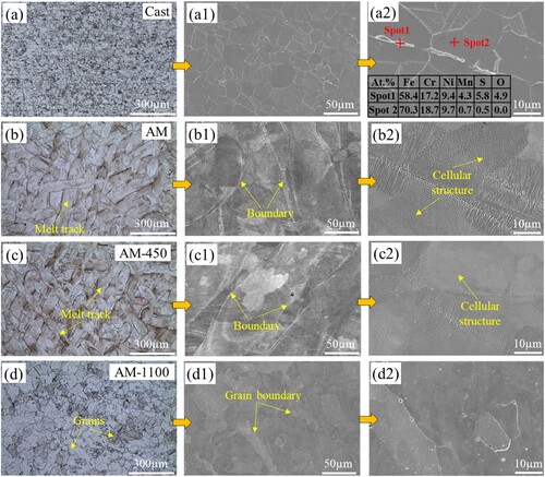
After post-annealing at 450 °C for 3 h, the morphology and size of the melt track and boundary are maintained, as displayed in (c,c1). As expected, no recovery and recrystallization occur in the samples due to the low heat-treatment temperature. In particular, the cellular structure morphology and size are also similar to the AM one. This indicates that element segregation is not eliminated and the cellular structure has high thermal stability. Wang et al. [Citation23] reported that the cellular structure will disappear with 2 h heat treatment at 800°C. Here, After being subjected to heat treatment at 1100°C for 1 h, the melt tracks and melt track boundaries disappear, which are replaced by large grains and grain boundaries as shown in (d,d1). This indicates the microstructure is homogenised. Moreover, it can be observed from (d2) that the fine cellular structures also disappear and are replaced by polygonal grains with tiny white dots. These dots are oxygen inclusions and MnS precipitate. Yan et al. [Citation24] found that these inclusions will form and grow when heat treated at high temperatures and with a long holding time in the LPBF 316L stainless steel. However, the size of inclusions in AM-1100 samples is significantly smaller than that in cast ones, indicating a more homogeneous microstructure and element distribution. The difference in microstructure may influence the mechanical properties, coating performance, and corrosion behaviour, which will be studied in the following sections.
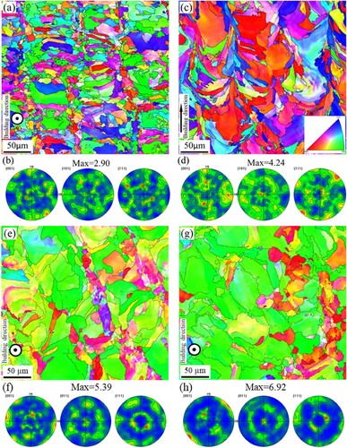
Due to the existence of melt tracks and cellular structures in the AM and AM-450 samples, their grain morphologies cannot be observed directly. Therefore, EBSD was performed on the AM sample to display the microstructure in detail including two planes perpendicular and parallel to the building direction, as illustrated in (a–d). The plane perpendicular to the building direction is predominantly composed of roughly quadrilateral columnar grains that are distributed along the melt tracks ((a)). The plane parallel to the building direction, however, consists of elongated grains oriented along the building direction ((c)). It should be noted that the texture is very weak ((b,d)). This is attributed to the 67.5°-rotation scanning strategy during the LPBF process, which weakens grain epitaxial growth along the building direction. Marattukalam et al. [Citation25] also reported that the rotated scanning strategy will break the epitaxy of columnar growth in the LPBF 316L steel. The grain morphology of the LPBF 316L stainless steel is observed to exhibit significant differences compared to its cast counterpart ((a)). These variations in grain may consequently lead to disparities in mechanical property and corrosion resistance. In addition, to evaluate the changes in texture and grain size of the LPBF samples after heat treatment, EBSD was also performed on the samples with heat treatment at low and high temperatures, as shown in (e–h). It can be seen that the <110>//BD fibre texture grows stronger after heat treatment, especially at the temperature of 1100 °C. Moreover, the grain also grows significantly compared to the as-built sample after heat treatment at high temperatures, which is consistent with the report by Salman et al. [Citation26].
Figure 2. EBSD analysis of AM samples, (a, c, e, g) IPF images with grain boundaries and (b, d, f, h) PF images: (a, b) the AM sample with plane perpendicular to and (c, d) the plane parallel to the building direction, (e, f) the AM-450 sample with plane perpendicular to the building direction and (g, h) the AM-1100 sample with plane perpendicular to the building direction.
The phase evolution of different samples is analysed using the XRD spectrum, as shown in . For the samples without coating, they are only composed of austenite phase (FCC, γ) (indexed by JCPDS-card 31-0619) and there is no trace of ferrite phase (BCC, δ) because the rapid solidification suppresses the formation of δ phase [Citation27]. In addition, it can be seen from the right magnification corresponding to the black dashed box that the diffraction peak (220) at ∼74.5° of AM samples moves slightly to the left (low 2θ) compared with the cast ones. Zhang et al. [Citation28] found that this was mainly due to the thermal residual stress and lattice distortion caused by the LPBF process. Bai et al. [Citation29] found the same lattice distortion in LPBF CuCrZr alloy. As a result, the lattice plane distance subsequently increases slightly, and the diffraction peak slightly shifts to the left according to Bragg's law. After heat treatment, the diffraction peak locations become the same as that of the cast one, which means the lattice distortion has been effectively alleviated during heat treatment. In particular, the diffraction peak location of AM 450 sample is also the same as the cast one, which indicates a release of residual stress and lattice distortion at a low heat treatment temperature, despite a similar microstructural morphology to AM. Moreover, the diffraction peak (220) of the AM sample is much stronger than that at other locations compared to the cast one, displaying an obvious preferred orientation. The same preferred orientation was also reported by Moyle et al. [Citation30] when characterising the LPBF 316L stainless steel. This is mainly caused by the unique layer-by-layer and bottom-up building method of the LPBF process. After heat treatment at 450 °C, the XRD pattern remains the same. When heat treated at 1100 °C, the maximum diffraction peak also remains the same with a little reduction in the intensity. This indicates that recovery and recrystallization have occurred, but the preferred orientation is not eliminated.
Figure 3. XRD patterns of the cast and LPBF 316L stainless steel with and without coatings under different heat treatments.
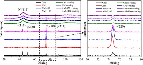
After coating, a broadening diffraction peak with high intensity is observed at 44.7°, which corresponds to the crystal plane (111) of nickel [Citation31]. However, there are no other diffractions along (200), (220), (311) and (222) identical to the standard diffraction pattern data of pure nickel. This indicates that the Ni-P coating is composed of an amorphous structure. It is well known that the crystal characteristic of the Ni-P coating is sensitive to phosphorus content. High phosphorus content will inhibit the crystallization of the Ni-P coatings. Keong and Sha [Citation32] reported that Ni-P coating will change from crystalline to mixed crystalline and amorphous to amorphous in turn with the increase of the phosphorus content. In this study, the phosphorus content of all the Ni-P coatings belongs to high phosphorus in the amount of 14–16 wt.% confirmed by EDS analysis, thereby resulting in amorphous structures. It should be noted that there is a reflection peak detected at 74.5°, which is the diffraction peak of the substrate. When conducting an XRD test, some strong peaks of the substrate will be observed during testing because the coating layer is penetrated by X-rays. The reason for the stronger peaks in AM and AM-450 samples than those in the cast and AM-1100 samples is their high intensity of γ (220) peaks. It should also be mentioned that all the samples with coatings have the same diffraction pattern in terms of the Ni phase, which means the microstructure has a negligible effect on the phase composition of the coating.
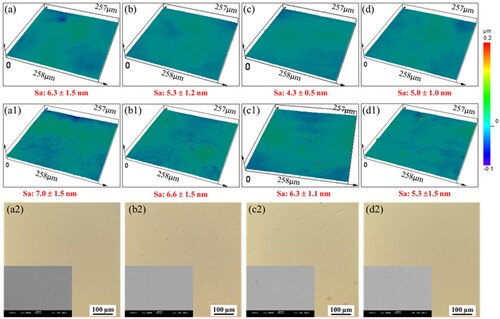
The surface roughness of the samples with and without coating is recorded using a confocal microscope. The results are displayed in . From the 3D-depth profile image, the surface roughness of the coated samples is slightly higher than the corresponding substrates. However, the difference is only 0.3–2 nm. From (a2–d2), the surfaces of all coated samples are flat without large particles. The melt tracks and cellular structures in AM and AM-450 samples also have a negligible effect on the coating surface morphology. It also should be noted that the P contents in the coatings on the cast, AM, AM-450, and AM-1100 substrate samples are 15.83 ± 1.01%, 14.73 ± 0.73%, 15.46 ± 0.89%, and 15.52 ± 0.82%, respectively, which belongs to Ni-P coatings with a high phosphorus content. The high P content causes the formation of complete amorphous phases in the coatings, which can also be seen from the XRD patterns shown in [Citation33]. Therefore, no typical globular topography formed as in the Ni-P coatings with low P content, which is also the main reason for higher surface quality compared to the one with surface roughness values of 1.6–1.8 µm (Sa) reported by Salicio-Paz et al. [Citation34].
Figure 4. Optical confocal and SEM micrographs: (a-a2) Cast, (b-b2) AM, (c-c2) AM 450, (d-d2) AM1100 samples (a-d) with and (a1-d1) without coating, (a2-d2) coated sample surface.
3.2. Coating interface and performance
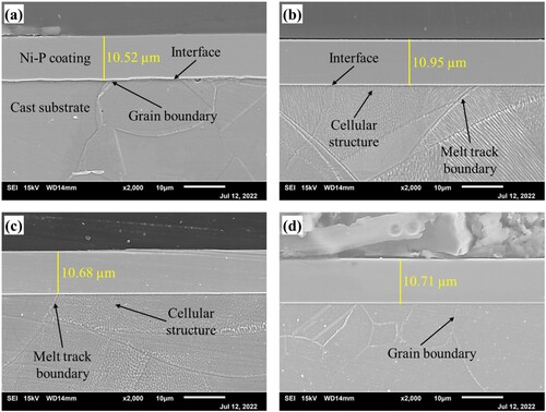
displays the Ni-P coating cross-sectional morphologies observed by SEM after polishing and etching in dilute aqua regia. An interface between the coating and substrate is observed clearly due to the display of substrate microstructure after etching. The average thickness of the coating on cast, AM, AM-450 and AM-1100 substrates are 10.52 µm ((a)), 10.95 µm ((b)), 10.68 µm ((c)) and 10.71 µm ((d)), respectively. It is known that the difference between all samples in coating thickness is very small, which indicates a negligible influence of microstructure and heat treatment state on the Ni–P coating thickness on 316L stainless steel. In addition, the coatings are uniform without structural defects and cracks at the interfaces for all samples. This indicates that an excellent interface can be observed between the Ni-P coating and LPBF 316L stainless steel. It should be noted that the interface of the LPBF samples ((b)) is much flatter than that of the cast one ((a)). Moreover, the contact regions between the coating and cellular structure, melt track boundary and grain boundary are also the same as other regions, which means the above characteristics have a negligible effect on the coating interface morphology. Therefore, it can be concluded that the Ni-P coating can be successfully deposited on the LPBF metal parts regardless of the microstructure and residual stress. The Ni-P coating can be taken as an effective candidate for the surface post-fabricating process for the LPBF metal parts.
Figure 5. Cross-sectional SEM images of the coated samples after etching, (a) cast, (b) AM, (c) AM-450, (d) AM-1100.
An instrumented indentation test was conducted on the cast and LPBF 316L stainless steel parts with and without coatings, as shown in (a,b). The microhardness of LPBF samples is much higher than that of the cast counterpart with a maximum difference of 49.3% as presented in (a). The AM samples display the highest microhardness, followed by AM-450 and AM-1100. The reason for the high microhardness of the AM samples is mainly due to the fine cellular substructures and dislocations caused by a high cooling rate during the LPBF process [Citation35]. During deformation, the cellular structure wall will interact with the deformation twins and strongly hinders the dislocation movement, resulting in an increase in strength. Under 3 h heat treatment at 450 °C, the microhardness remains at a high level with a negligible reduction. This is because the microstructure is basically unchanged, as shown in (c). In contrast, the microhardness of the AM-1100 sample decreases significantly due to the disappearance of the fine cellular structures. After being deposited with Ni-P coatings, the surface microhardness of all samples increases sharply due to the excellent mechanical strength of Ni-P coatings. In particular, the microhardness of the AM sample increases dramatically by 144.6% to ∼ 800 HV. The coated cast sample has the lowest microhardness but it is still up to 780 HV. The slight difference in the microhardness may be due to differences in P content in different coatings. It is well known that a high P content will result in the reduction of mechanical properties. Buchtík et al. [Citation36] observed a reduction of microhardness when the P content increased from 5.2% to 10.8%. The EDS results show that the coated AM sample has the lowest P content with 14.73% compared with the coated cast sample with a value of 15.83% (Fig. S1 in Supplementary material). Therefore, it can be concluded that the coatings can significantly improve the surface microhardness of both cast and LPBF 316L stainless steel parts.
Figure 6. (a) Hardness results derived from instrumented indentation load-displacement curve and (b) load-displacement curves.
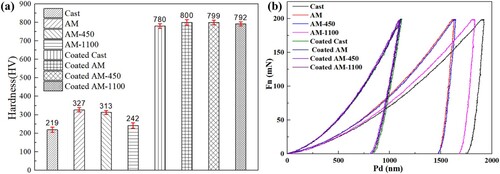
To characterise the micro-mechanical properties, the instrumented indentation load-displacement curves of all samples were displayed in (b). It is evident that the indentation displacement with the coating is much smaller than that of the substrates for all samples, which indicates higher resistance to material deformation of the coatings than that of the substrate samples, which is consistent with the microhardness in (a). For the bare substrates, the cast sample has the largest displacement, followed by AM-1100 sample, AM-450 sample, and AM sample, which indicates the strength of AM sample is the highest and the cast sample is the lowest. However, after depositing Ni-P coatings, the curves of the samples are basically coincident, which indicates the negligible effect of the substrate's original strength on the coating micro-mechanical property. This is because the indentation depth is kept at less than 10% of the coating thickness, hence the load-displacement curves represent the coating responses to the indentation force.
shows the scratch morphologies of the cast and LPBF 316L stainless steel parts without coatings after the ramping load scratch test. Due to the tensile and compressive stresses formed during the scratching test, the damage characteristic of the materials is complex [Citation36]. There are mainly three characteristic regions on the scratched area, which are scratch groove, plastic accumulation region, and affected region, respectively ((a)). The plastic accumulation region is on the edge of the scratch groove, which is mainly formed due to the accumulation of material during scratching test process. The affected region is adjacent to the plastic accumulation region, which is formed due to the push from the latter. A large number of slip steps are observed at the plastic accumulation and affected regions of the cast sample ((a)), followed by the AM-1100 sample ((d)). This is because 316L stainless steel mainly consists of single-phase austenite as shown in , whose crystal structure is face-centered cubic with a dozen slip systems. Therefore, under the deformation during scratching test, slip steps are easily formed.
Figure 7. Scratching morphologies of the cast and LPBF 316L stainless steel parts without coatings: (a) cast, (b) AM, (c) AM-450, and (d) AM-1100. The yellow dotted arrows point to the crack-like defect region.
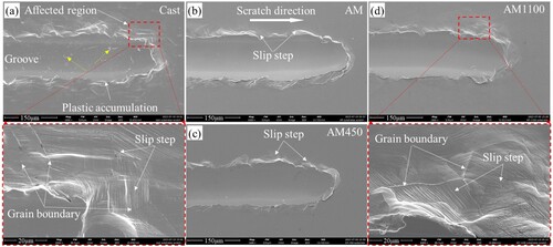
However, the slip steps are very few on the AM ((b)) and AM-450 samples ((c)). This is mainly attributed to the high deformation resistance caused by fine celluar structures formed during LPBF process, as shown in (b,c). Wang et al. [Citation35] reported that the fine celluar structure wall can enhance dislocation pinning, resulting in the improvement of strength of LPBF metals. In addition, Liu et al. [Citation4] found that only partial dislocation can go through the celluar structure wall when they observed the dislocation movement in the LPBF 316L stainless steel using the in-situ TEM method. As a result, the slip steps are difficult to form in these materials. The reason for observable slip steps appeared in the AM-1100 sample is the disappearance of fine celluar structures, as shown in (d). It should be noted that crack-like defects (marked by yellow dotted arrows) were observed in the scratching groove of the cast sample ((a)). However, no such defects were observed in the grooves of the LPBF samples with and without heat treatment ((b–d)). The formation of the crack-like defect may be caused by the inclusions at the grain boundary in the cast sample ((a)), which leads to a large deformation mismatch between the adjacent grains during scratching test process. The change in the characteristics of the scratch groove reflects the deformation level of the substrates, where the AM and AM-450 samples have higher deformation resistance, whch is consistent with the higher hardness in .
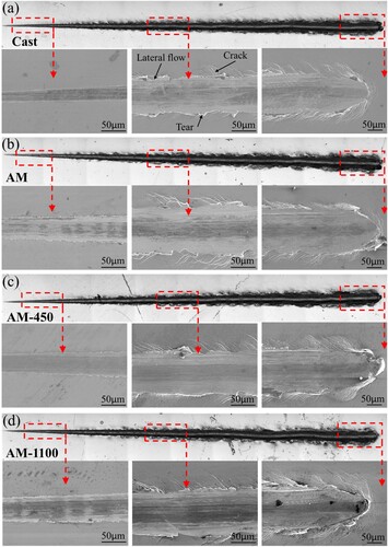
A ramping load scratch test was also carried out on the coatings of both cast and LPBF samples to further evaluate the coating adhesion performance on the substrate. The scratch morphologies are presented in with a final load of 30 N. It is different from the 316L stainless steel without coatings in the scratched surface morphology that the severe plastic deformation and slip steps are replaced by a large number of cracks around the scratched grooves. The crack features are identified with the aid of ‘edge’ effect, where two edges were found compared to the slip steps with only one single edge [Citation37]. This is mainly caused by the much higher brittleness of the coating compared to the substrate. When the deformation of the coating material is not enough to absorb the energy imparted by the indenter during the scratching test, the material will fracture to release the excess energy. The critical load is usually used to estimate the adhesion between the coating and substrate. In this study, the critical loads of the coated cast, coated AM, coated AM-450, and coated AM-1100 samples are 18.2, 20.3, 22.0, and 22.2 N, respectively. The coated LPBF samples have a slightly higher critical load than that of the cast ones, which may be related to the better interface quality of the former ones, as shown in .
Figure 8. Scratching morphologies of the coated cast and LPBF 316L stainless steel parts: (a) cast, (b) AM, (c) AM-450 and (d) AM-1100.
shows the frictional force versus load for the scratch test of both cast and LPBF 316L stainless steels. There are three stages for all the samples, which are smooth zone (I), small vibration zone (II), and large vibration zone (III). From the SEM images of the scratch grooves in each subfigure of , it can be known that Zone I corresponds to the image on the left, in which only wear occurs, and plastic deformation dominates around the grooves. Zone II corresponds to the image in the middle, in which some cracks (failures) appear on the edge of the grooves, thereby resulting in a small fluctuation in frictional force. Zone III corresponds to the image on the right, in which the substrate is also scratched beside the cracks on the edge of the grooves, thus resulting in a large fluctuation in frictional force.
Figure 9. Frictional force versus load for the scratch test of Ni-P coatings on the cast and LPBF 316L stainless steel.
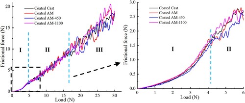
With the scratch test continuing, a large number of transverse cracks appear beside the grooves. However, there are no cracks observed in the scratch grooves (i.e. the contact region between the tip and coating) throughout the test process for all samples although the depth (more than 15 µm) of the scratch groove at the end has exceeded much more than the coating thickness (less than 11 µm). Only wear is observed in the grooves, which indicates a good interface adhesion between the coatings and substrates. It can be seen from that although the frictional force fluctuates much more in zone III, there is no sharp increase in the frictional force between zones II and III. The main reason may be that the shear stress induced by the indentation tip is lower than the limit of adhesion, thereby resulting in the absorption of the energy from indentation via the elastic-plastic behaviour of the coating and substrate without breakage.
3.3. Corrosion behaviour
3.3.1. Potentiodynamic polarisation
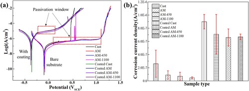
The potentiodynamic polarisation experiments were conducted in 3.5 wt.% NaCl solution for the investigated samples, and the results are displayed in . The coated samples have lower corrosion potential than their corresponding substrates as shown in (a). This is attributed to the disparities in chemical composition between the substrate and coating. Therefore, the Ni-P coating is an anodic coating of the substrate, which means that the coating provides sacrificial protection to the substrate. In other words, the coatings can effectively act as a barrier layer between the substrate and the corrosive environment; even when the coating is damaged, the coatings can act as an anode and corrode prior to the substrate. The potentiodynamic polarisation curves for both the bare substrates and the coated samples exhibit passivation regions, as illustrated in (a). The coated samples have smaller passivation windows (as marked by the red dotted box) than that of the bare substrates. The size of the passivation window between the coatings on different substrates is negligible. For the bare substrates, LPBF samples have larger passivation windows than that of the cast ones. The larger passivation window means that the substrates can resist the occurrence of pitting expansion to stable pitting over a wide range of potentials. The lower breakdown potential of the cast substrates may be attributed to the larger size of inclusions ((a2)), which results in compositional fluctuation and subsequently affects the homogeneity of the passive film. As a consequence, there are larger fluctuations in corrosion current and an increased possibility of passive film breakdown. The corrosion current density obtained from the polarisation curve in (a) using Tafel fitting method with the potential range of −100 mV to +100 mV vs. SCE is presented in (b). The coated samples show higher corrosion current density than the bare substrates. This is also attributed to the chemical activity difference between the substrates and the coatings. For the substrates, corrosion current densities are in descending order: cast, AM, AM-450 and AM-1100. The coated cast samples show a larger corrosion current density than that of the AM coated samples. The heat treatment of the substrates can further improve their corrosion resistance. This may be attributed to two factors. One is the heat treatment effectively mitigated the residual stress generated during the printing process; another is the grain boundary of the LPBF samples is less sensitive to corrosion compared to cast ones. The similar corrosion potential (Ecorr) for each group may be due to the approximately same chemical composition. The corrosion potentials of 316L stainless steel fabricated through selective laser melting, laser metal deposition, and traditional wrought methods were also found to be comparable in the study conducted by Revilla et al. [Citation7], where the average value of Ecorr calculated taking into account the measurements conducted in all the samples was −73 ± 10 mV.
Figure 10. Results of potentiodynamic polarisation test in neutral 3.5% NaCl solution: (a) polarisation curves, and (b) current density.
3.3.2. Characterisation of corroded surfaces
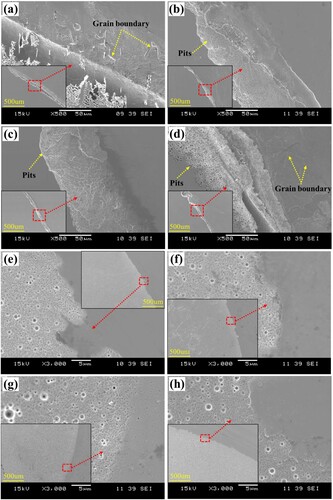
To further analyse the corrosion behaviour of the LPBF 316L stainless steel with and without Ni-P coatings, the corrosion morphologies after the potentiodynamic polarisation test (stopped at 10 mA/cm2) are observed under SEM, as shown in . It can be seen that the corrosion of the substrates is mainly localised corrosion. From (a) it has been known that there exists passivation behaviour of the substrates. However, the passive film on the substrates is not uniformly distributed. Due to the presence of precipitates and grain boundaries, certain regions are more susceptible to corrosion. If there is a breakdown in a small area of the passive film that cannot be repassivated promptly, a corrosion couple will form between the affected area and the surrounding passive region, hindering repassivation of the breakdown area and initiating pitting corrosion. As mass diffusion within these pits becomes restricted, pH levels decrease along with dissolved oxygen due to increased iron ion concentration. In order to maintain solution electroneutrality, chloride ions become enriched, further promoting damage to the passive film and formation of larger depth of localised corrosion while inhibiting the initiation of new pits. The severity of the corrosion can reflect the protectiveness of the passive films and the localised corrosion susceptibility of the substrates [Citation38]. A closer look at the corrosion morphology of the bare substrates, also reveals a notable difference. The corrosion morphology of the cast substrate is similar to that of the AM-1100 sample, including interstitial morphology formed by more severe localised corrosion. However, this morphology does not appear in the AM and AM-450 samples. Besides, the width of the corrosion area in the cast samples is wider than in the LPBF samples. And there are more pits on the LPBF samples regardless of heat treatment compared with cast substrates. At the corroded area of the cast and AM-1100 samples, grain boundaries (as marked by yellow dotted arrows) are clearly presented. While for AM and AM-450 samples, melton boundaries and substructures are appeared. Together with the size of the passivation window in (a), this implies that the microstructural differences induced by heat treatment can affect the passivation stability of the LPBF samples. The grain boundaries may act as vulnerable areas and cause severer localised corrosion. The presence of precipitates at the grain boundaries, as observed by Laleh et al. [Citation39] during their investigation on intergranular corrosion in LPBF and commercial 316L stainless steel, accounts for this phenomenon. Although grain boundaries also appeared in (d), it is not as clear as that in the cast samples. This may be due to the short solution heat treatment time, which limits the formation of precipitates in the grain boundary region [Citation23]. While the coated samples show uniform corrosion on the whole surface exposure to the electrolyte. The corrosion morphologies are similar and uniformly distributed on the tested surface area. Compared with the corrosion morphology of the bare substrates, it can be concluded that the coating can effectively protect the substrate from localised corrosion.
Figure 11. Surface morphologies of (a, b, c, d) substrates and (e, f, g, h) coated samples obtained by SEM after potentiodynamic polarisation test in neutral 3.5% NaCl solution: (a, e) cast, (b, f) AM, (c, g) AM-450, and (d, h) AM-1100.
3.3.3. Electrochemical impedance spectroscopy
EIS has been systematically implemented as a robust tool for investigating interfacial processes in the fields of corrosion and coatings [Citation40]. For coated samples, EIS results not only show the information on the coating-electrolyte interface but also the protective efficiency of the coatings. EIS test results of the bare substrates under different heat treatment conditions and corresponding coated samples are displayed in . Experimental data are fitted using an equivalent circuit based on a modified Randle circuit, as shown in (a,b). The substitution of pure capacitance with a constant phase element (CPE) is commonly employed in the investigation of non-ideal systems, such as those exhibiting heterogeneity on the electrode surface [Citation41]. Zhang et al. [Citation42] also replaced capacitance with CPE when investigating the corrosion behaviour of mild steel with Fe-based amorphous alloy coating. Since the Bode phase diagram consists of broad peaks representing two overlapping peaks, the proposed equivalent circuit consists of two-time constants. For the bare substrates, one time constant is referred to as the electrochemical behaviour of passive film (CPE1) and the other is referred to as the electrical double layer (CPE2). For the coated samples, two time constants are account for the electrochemical behaviour of the coating (CPEc) and metal-coating interface (CPEdl), respectively. Rs represents a constant resistance related to electrolyte resistance and the electrode material. Rf refers to the passive film resistance, Rpo is the pore electrical resistance to the ionic current through the pores, and Rct is charge transfer resistance.
Figure 12. (a) Nyquist plots, and (b, c)bode plots of the substrate and coated samples.
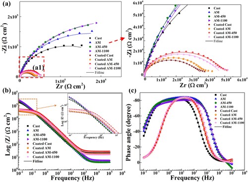
Figure 13. Equivalent electrical circuit of substrates (a), coated samples (b), (c) Rf/Rpo obtained from fitting results by the proposed equivalent electrical circuit.
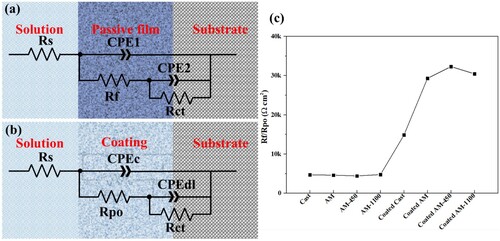
As shown in (a), a larger capacitive arc is presented for the substrates compared with that of the coated samples, indicating a decisive influence of the alloy composition. However, significant difference can also be observed for samples with similar composition. The cast samples exhibit a smaller capacitive arc compared to the AM samples for the substrates, and the diameter of the capacitive arc of the AM sample further enlarges after heat treatment ((a)). This trend is further supported by the modulus value in the low frequency range depicted in (c), which suggests that the polarisation resistance (the sum of Rf and Rct) of the cast samples is inferior to that of their LPBF counterparts, indicating a lower corrosion resistance for the former. These results are consistent with those obtained from polarisation tests. For the coated samples, the coated LPBF samples show a larger capacitive arc than the coated cast ones. From the bode plot in (c), the coated cast samples show a smaller modulus than that of the other samples. This may be due to there exist pinholes in the coatings, and the penetration of the electrolyte in the coating on cast samples is severer than that of the coated LPBF samples. To provide more direct information, the Rf/Rpo value extracted from EIS fitting data (Table S1 in Supplementary material) using the proposed equivalent electrical circuit model is presented in (c). The passive film resistance of the bare substrates is similar and smaller than the pore resistance of coated samples, which means the coatings formed an effective barrier between the substrate and electrolyte. The Rpo value of the coated cast sample is lower than the coated LPBF samples regardless of the heat treatment. The pore resistance of coated cast samples is the smallest, and that of the coated AM-450 sample is the largest. The increase in pore resistance indicates a more compact coating, which can be attributed to the low-temperature heat treatment that effectively reduces residual stress in LPBF substrates and facilitates the formation of a denser coating [Citation43]. However, higher temperature heat treatment increased the grain size and precipitates at the grain boundaries, reducing the pore resistance of coated AM-1100 samples. The sensitisation of the grain boundaries in the AM-1100 samples is comparatively milder than that in the cast ones, as shown in (a,d). Consequently, the coated AM-1100 samples still demonstrate superior pore resistance compared to the coated cast samples. This is consistent with the interface morphology in (a,d), which shows better interface quality between the coating and the AM-1100 substrates than that of the cast substrates.
4. Conclusions
In this study, heat treatment processes are conducted on the LPBF 316L stainless steel parts. Then, electroless Ni-P coatings are deposited on the corresponding 316L stainless steel substrates with and without heat treatment. The microstructure, surface morphology, mechanical property, adhesion strength, and the subsequent influence on corrosion behaviour are systematically investigated. The primary conclusions can be drawn as follows:
Low-temperature (450 °C) annealing treatment can effectively alleviate lattice distortion of the as-built (AM) samples which is confirmed by the XRD analysis although the microstructure features remain the same as that in the AM sample. After annealing treatment at a high temperature (1100 °C), the cellular structure, melt tracks, and melt track boundaries disappear completely.
The defect-free electroless Ni-P coatings with a nanoscale surface roughness (Sa) are successfully deposited on the LPBF 316L steel parts under different heat treatment conditions. The overall hardness of the substrates is significantly increased by the Ni-P coatings (from ∼219–327 HV to ∼780–800 HV). The microstructure and microhardness of the substrate have a negligible effect on the thickness, amorphous coating structure, and microhardness of the coatings.
The AM and low-temperature-treated samples have higher deformation resistance attributed to the fine cellular structures than the cast counterpart with typical coarse polygonal grains. However, the deformation resistance decreases due to the disappearance of cellular structures after annealing treatment at a high temperature (1100 °C), herein resulting in severe plastic accumulation and a large number of slip steps around the scratch groove.
No cracks are formed in the bottom of the grooves during the scratch test of the coatings, which indicates excellent adhesion performance between the coatings and substrates, including cast, AM, and heat-treated LPBF samples. In addition, the coated LPBF samples have a similar critical load (20.3–22N) which is slightly higher than that of the cast ones (18.2 N).
The potentiodynamic polarisation and electrochemical impedance spectroscopy (EIS) tests reveal that the coated AM-450 samples demonstrate superior corrosion resistance compared to the other coated LPBF samples, as evidenced by a smaller corrosion current density and a larger capacitive arc. Additionally, it is observed that both cast substrates and coated cast samples exhibit the lowest level of corrosion resistance.
CRediT authorship contribution statement
Cuiling Zhao: Writing – original draft, Validation, Methodology, Investigation, Formal analysis, Data curation, Conceptualisation. Yunfa Guo: Methodology, Data curation. Yun Yang: Formal analysis, Data curation. Yuchao Bai: Data curation, Writing – review & editing. Bing Li: Writing – review & editing. Wen Feng Lu: Resources, Writing – review & editing. Kaiyang Zeng: Resources, Writing – review & editing. Hao Wang: Conceptualisation, Investigation, Formal analysis, Writing – review & editing, Supervision, Resources, Funding acquisition.
Supplemental Material
Download MS Word (1.2 MB)Disclosure statement
No potential conflict of interest was reported by the author(s).
Data availability statement
The raw/processed data required to reproduce these findings cannot be shared at this time as the data also forms part of an ongoing study.
Additional information
Funding
References
- Qi Y, Zhang H, Yang X, et al. Achieving superior high-temperature mechanical properties in Al-Cu-Li-Sc-Zr alloy with nano-scale microstructure via laser additive manufacturing. Mater Res Lett. 2024;12:17–25. doi:10.1080/21663831.2023.2285388
- Zhao D, Han C, Peng B, et al. Corrosion fatigue behavior and anti-fatigue mechanisms of an additively manufactured biodegradable zinc-magnesium gyroid scaffold. Acta Biomater. 2022;153:614–629. doi:10.1016/j.actbio.2022.09.047
- DebRoy T, Wei HL, Zuback JS, et al. Additive manufacturing of metallic components – process, structure and properties. Prog Mater Sci. 2018;92:112–224. doi:10.1016/j.pmatsci.2017.10.001
- Liu L, Ding Q, Zhong Y, et al. Dislocation network in additive manufactured steel breaks strength–ductility trade-off. Mater Today. 2018;21:354–361. doi:10.1016/j.mattod.2017.11.004
- Saravanan M, Devaraju A, Venkateshwaran N, et al. A review on recent progress in coatings on AISI austenitic stainless steel. Mater Today Proc. 2018;5:14392–14396. doi:10.1016/j.matpr.2018.03.024
- Zhao C, Bai Y, Zhang Y, et al. Influence of scanning strategy and building direction on microstructure and corrosion behaviour of selective laser melted 316L stainless steel. Mater Des. 2021;209:109999. doi:10.1016/j.matdes.2021.109999
- Revilla RI, Van Calster M, Raes M, et al. Microstructure and corrosion behavior of 316L stainless steel prepared using different additive manufacturing methods: a comparative study bringing insights into the impact of microstructure on their passivity. Corros Sci. 2020;176:108914. doi:10.1016/j.corsci.2020.108914
- Lou X, Song M, Emigh PW, et al. On the stress corrosion crack growth behaviour in high temperature water of 316L stainless steel made by laser powder bed fusion additive manufacturing. Corros Sci. 2017;128:140–153. doi:10.1016/j.corsci.2017.09.017
- Tromas C, Stinville JC, Templier C, et al. Hardness and elastic modulus gradients in plasma-nitrided 316L polycrystalline stainless steel investigated by nanoindentation tomography. Acta Mater. 2012;60:1965–1973. doi:10.1016/j.actamat.2011.12.012
- Lang FC, Xing YM, Zhu J, et al. Study of the mechanical properties of a nanostructured surface layer on 316L stainless steel. Adv Mater Sci Eng. 2016;2016:1–9. doi:10.1155/2016/7517616
- Lyu Y, Chen Y, Wan Y. A novel post-processing method for 316L steel specimen generated by SLM using TiN/TiAlN multilayer coating. Rapid Prototyp J. 2020;26:1477–1483. doi:10.1108/RPJ-07-2019-0199
- Groden C, Traxel KD, Afrouzian A, et al. Inconel 718-W7Ni3Fe bimetallic structures using directed energy deposition-based additive manufacturing. Virtual Phys Prototyp. 2022;17:170–180. doi:10.1080/17452759.2022.2025673
- Yao L, Huang S, Ramamurty U, et al. On the formation of “fish-scale” morphology with curved grain interfacial microstructures during selective laser melting of dissimilar alloys. Acta Mater. 2021;220:117331. doi:10.1016/j.actamat.2021.117331
- Yao L, Xiao Z, Huang S, et al. The formation mechanism of metal-ceramic interlayer interface during laser powder bed fusion. Virtual Phys Prototyp. 2023;18; doi:10.1080/17452759.2023.2235324
- Menon V, Aranas C, Jr., Saha G. Cold spray additive manufacturing of copper-based materials: review and future directions. Mater Sci Addit Manuf. 2022;1(2):1–20. doi:10.18063/msam.v1i2.12
- Loto CA. Electroless nickel plating. A review. Silicon. 2016;8:177–186. doi:10.1007/s12633-015-9367-7
- Fang X-x, Zhou H-z, Xue Y-j. Corrosion properties of stainless steel 316L/Ni-Cu-P coatings in warm acidic solution. Trans Nonferrous Met Soc China (English Ed.). 2015;25:2594–2600. doi:10.1016/S1003-6326(15)63880-8
- León OA, Staia MH, Hintermann HE. High temperature wear of an electroless Ni-P-BN (h) composite coating. Surf Coatings Technol. 2003;163–164:578–584. doi:10.1016/S0257-8972(02)00663-1
- A. C1624-05. Standard test method for adhesion strength and mechanical failure modes of, ASTM Int. C1624-05 (2012) 1–29. 2015. doi:10.1520/C1624-05R15.Scope
- Liu Z, Zhao D, Wang P, et al. Additive manufacturing of metals: microstructure evolution and multistage control. J Mater Sci Technol. 2022;100:224–236. doi:10.1016/j.jmst.2021.06.011
- Wen X, Wang C, Gong Y, et al. Microstructure and mechanical properties of FeCoNiCrAl high-entropy alloys by selective laser melting. Chinese J Mech Eng Addit Manuf Front. 2023;2:100069. doi:10.1016/j.cjmeam.2023.100069
- Bai Y, Zhao C, Zhang J, et al. Abnormal thermal expansion behaviour and phase transition of laser powder bed fusion maraging steel with different thermal histories during continuous heating. Addit Manuf. 2022;53:102712. doi:10.1016/j.addma.2022.102712
- Wang K, Chao Q, Annasamy M, et al. On the pitting behaviour of laser powder bed fusion prepared 316L stainless steel upon post-processing heat treatments. Corros Sci. 2022;197:110060. doi:10.1016/j.corsci.2021.110060
- Yan F, Xiong W, Faierson E, et al. Characterization of nano-scale oxides in austenitic stainless steel processed by powder bed fusion. Scr Mater. 2018;155:104–108. doi:10.1016/j.scriptamat.2018.06.011
- Marattukalam JJ, Karlsson D, Pacheco V, et al. The effect of laser scanning strategies on texture, mechanical properties, and site-specific grain orientation in selective laser melted 316L SS. Mater Des. 2020;193:108852. doi:10.1016/j.matdes.2020.108852
- Salman OO, Gammer C, Chaubey AK, et al. Effect of heat treatment on microstructure and mechanical properties of 316L steel synthesized by selective laser melting. Mater Sci Eng A. 2019;748:205–212. doi:10.1016/j.msea.2019.01.110
- Farshidianfar MH, Khajepour A, Gerlich AP. Effect of real-time cooling rate on microstructure in laser additive manufacturing. J Mater Process Technol. 2016;231:468–478. doi:10.1016/j.jmatprotec.2016.01.017
- Zhang X, Chen L, Zhou J, et al. Simulation and experimental studies on process parameters, microstructure and mechanical properties of selective laser melting of stainless steel 316L. J Brazilian Soc Mech Sci Eng. 2020;42:1–14. doi:10.1007/s40430-020-02491-3
- Bai Y, Zhao C, Zhang Y, et al. Additively manufactured CuCrZr alloy: microstructure, mechanical properties and machinability. Mater Sci Eng A. 2021;819:141528. doi:10.1016/j.msea.2021.141528
- Moyle M, Ledermueller C, Zou Z, et al. Multi-scale characterisation of microstructure and texture of 316L stainless steel manufactured by laser powder bed fusion. Mater Charact. 2022;184:111663. doi:10.1016/j.matchar.2021.111663
- Guo SQ, Hou LF, Guo CL, et al. Characteristics and corrosion behavior of nickel-phosphorus coatings deposited by a simplified bath. Mater Corros. 2017;68:468–475. doi:10.1002/maco.201609155
- Keong KG, Sha W. Crystallisation and phase transformation behaviour of electroless nickel – phosphorus deposits and their engineering properties. Surf Eng. 2002;18:329–343. doi:10.1179/026708402225010010
- Duncan RN. The metallurgical structure of electroless nickel deposits: effect on coating properties. Plat Surf Finish. 1996;83:65–69.
- Salicio-Paz A, Grande H, Pellicer E, et al. Monolayered versus multilayered electroless NiP coatings: impact of the plating approach on the microstructure, mechanical and corrosion properties of the coatings. Surf Coatings Technol. 2019;368:138–146. doi:10.1016/j.surfcoat.2019.04.013
- Wang YM, Voisin T, McKeown JT, et al. Additively manufactured hierarchical stainless steels with high strength and ductility. Nat Mater. 2018;17:63–71. doi:10.1038/nmat5021
- Buchtík M, Krystỳnová M, Másilko J, et al. The effect of heat treatment on properties of Ni-P coatings deposited on a AZ91 magnesium alloy. Coatings. 2019;9(7):461. doi:10.3390/coatings9070461
- Huang S, Kumar P, Yeong WY, et al. Fracture behavior of laser powder bed fusion fabricated Ti41Nb via in-situ alloying. Acta Mater. 2022;225:117593. doi:10.1016/j.actamat.2021.117593
- Kelly RG, Lee JS. Localized corrosion: crevice corrosion. In: Encyclopedia of interfacial chemistry: surface science and electrochemistry. Localized corrosion: crevice corrosion. Bonn: Elsevier; 2018. p. 291–301. doi:10.1016/B978-0-12-409547-2.13420-1
- Laleh M, Hughes AE, Xu W, et al. On the unusual intergranular corrosion resistance of 316L stainless steel additively manufactured by selective laser melting. Corros Sci. 2019;161:108189. doi:10.1016/j.corsci.2019.108189
- Lasia A. Electrochemical impedance spectroscopy and its applications, 2014. doi:10.1007/978-1-4614-8933-7
- Fonseca RM, Soares RB, Carvalho RG, et al. Corrosion behavior of magnetron sputtered NbN and Nb1-xAlxN coatings on AISI 316L stainless steel. Surf Coatings Technol. 2019;378:124987. doi:10.1016/j.surfcoat.2019.124987
- Zhang SD, Wu J, Qi WB, et al. Effect of porosity defects on the long-term corrosion behaviour of Fe-based amorphous alloy coated mild steel. Corros Sci. 2016;110:57–70. doi:10.1016/j.corsci.2016.04.021
- Cruz V, Chao Q, Birbilis N, et al. Electrochemical studies on the effect of residual stress on the corrosion of 316L manufactured by selective laser melting. Corros Sci. 2020;164:108314. doi:10.1016/j.corsci.2019.108314