
 ?Mathematical formulae have been encoded as MathML and are displayed in this HTML version using MathJax in order to improve their display. Uncheck the box to turn MathJax off. This feature requires Javascript. Click on a formula to zoom.
ABSTRACT
The objective of this study is to develop and evaluate self-sensing capabilities in additively manufactured parts by embedding conductive elements that are copper and continuous carbon fiber. Two sets of test specimen were manufactured using a custom g-code on material extrusion-based Anisoprint A4 machine. Each set contained copper and continuous carbon fiber in an amorphous thermoplastic matrix. A tailor-made test setup was developed by improvising the American Society for Testing and Materials (ASTM D790) three-point loading system. Electrical resistance measurements were conducted under flexural loads to evaluate the self-sensing capability of each test specimen. The results confirmed that material extrusion technology can allow production of self-sensing parts. The electrical resistance increases linearly (Sensing tolerance <±2.6%, R2>93.8% p-value < 0.005), establishing a strong correlation with applied force and strain. The work allows for creating smart parts that can facilitate big data collection, analysis, and evidence-based decision-making for condition monitoring and preventive maintenance needed for Industry 4.0.
Introduction
Additive manufacturing (AM), de facto known as 3D-printing, is rapidly emerging into a general-purpose technology to produce end-use parts from 3D model data [Citation1,Citation2]. As opposed to the subtractive and formative modes requiring part-specific tools for removal and pressurised shaping, the layer-by-layer AM principle allows for tool-less manufacturing with unprecedented geometric freedom [Citation3–5]. Owing to its digital and general-purpose characteristics, AM has been identified as the key enabler of Industry 4.0 facilitating the interface between physical and virtual environments through big data collection, analysis, and evidence-based decision-making [Citation6–9].
Leveraging the digital and general-purpose characteristics of AM, literature has proposed several methods for manufacturing parts with embedded components, for example, passive and active sensors, printed circuit boards, motors, gears, shafts, and bushings [Citation10–14]. Binnard [Citation11], Cham et al. [Citation12] and Prinz and Weiss [Citation14] highlighted an approach to embed components by depositing and removing material in layer-based cycles. Kataria and Rosen [Citation13] suggested a shape conversion method for embedding components in a primitive rectangular form for vat photopolymerization process. Akmal [Citation15] developed process interruption-based embedding using binder jetting, material extrusion, powder bed fusion, and vat photopolymerization methods. Feldhausen et al. [Citation16] have reported process interruption-based embedding of ceramic inserts using directed energy deposition and subtractive manufacturing.
Several studies have dispensed conductive inks, e.g. silver, to introduce electrical interconnects in parts using vat photopolymerization process [Citation17–20]. However, they are prone to poor conductivity as solid material due to high electrical resistance and to the requirement of high temperature for curing. Further, they may also cause electrical shorting [Citation21] when deposited in combination with material extrusion-based technique owing to inherent porosity. To yield higher current densities, emerging literature has embedded continuous copper wire (CCW) using in-house made and customised extrusion-based 3D printers [Citation22–24]. However, literature still lacks their printing parameters (e.g. deposition speed, tool head speed, layer thickness, etc.) and use-cases owing to highly tailor-made setups for embedding.
On the other hand, commercial solutions now exist for embedding continuous carbon fiber (CCF) because of its dominant reinforcement in polymer matrices [Citation25,Citation26]. Emerging studies have also been testing the self-sensing capabilities of CCF which eliminates the need for attached or embedded sensory elements [Citation27–31]. While externally attached sensory elements may be subjected to wear and tear depending on the environment, embedded sensory elements may be prone to degradation of structural integrity of the part depending on the size of the embedded sensors.
The aim of this study is to develop and evaluate the self-sensing capability of CCW and CCF embedded in a thermoplastic matrix using a commercially available material extrusion-based AM machine.
Methods
Test specimens
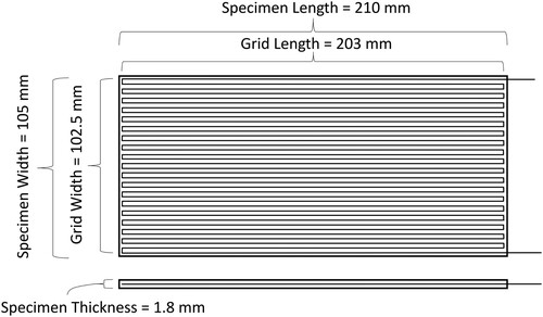
and depict two test specimen – Type A and Type B – that were designed using Creo Parametric (6.0.2.0, PTC, Needham, MA, USA). Type A contains one grid line composed of conductive element, i.e. CCF or CCW. Similarly, Type B contains 38 grid lines of identical conductive element.
Figure 1. Test specimen Type A (No. of grid lines = 1).
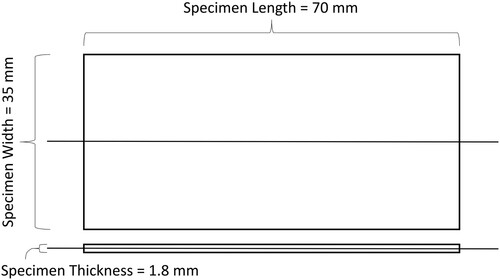
Figure 2. Test specimen Type B (No. of grid lines = 38).
Additive manufacturing
The Anisoprint A4 machine was used to additively manufacture the specimens composed of CCF and CCW in a thermoplastic matrix, i.e. polyethylene terephthalate glycol-modified (PETG). The CCF comprised of 1.5 k carbon fibers. The tow of CCF filament had a tensile strength of 2240 MPa, a tensile modulus of 149.5 GPa, and tensile ultimate strain of 1.325%. The CCW was a conventional copper wire (DASOL Grade 1, Class 155). It had an electrical resistance of 0.03401 Ω/m (diameter of 0.8 mm) according to IEC 60851-5.3. The machine followed the material extrusion principle in which material was selectively dispensed through a nozzle [Citation2]. The print head contained dual nozzle – one nozzle for dispensing the thermoplastic, and the second nozzle for dispensing the reinforcement filament which was equipped with a cutting device. The reinforcement filament nozzle dispensed both reinforcement material and PETG simultaneously. The test specimens were pre-processed using Anisoprint Aura (1.27.2, ANISOPRINT SARL, Esch-sur-Alzette, Luxembourg). shows the AM parameters.
Table 1. Global additive manufacturing parameters.
lists the recommended processing parameters of the proprietary CCF and the tailor-made processing parameters of the CCW using trial and error approach.
Table 2. Processing parameters of continuous carbon fiber and continuous copper wire.
Self-sensing under flexural loads
Two flexural fixtures were designed and manufactured by improvising the ASTM three-point loading system [Citation32]. and show the fixtures concomitant to Type A and Type B specimens. Type A fixture contained a support span-to-depth ratio of 26:1 and similarly, Type B contained a span-to-depth ratio of 78:1 to consider large deformations on the specimens and subsequently the conductive elements.
Figure 3. Flexural fixture for Type A specimen.
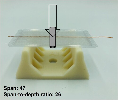
Figure 4. Flexural fixture for Type B specimen.
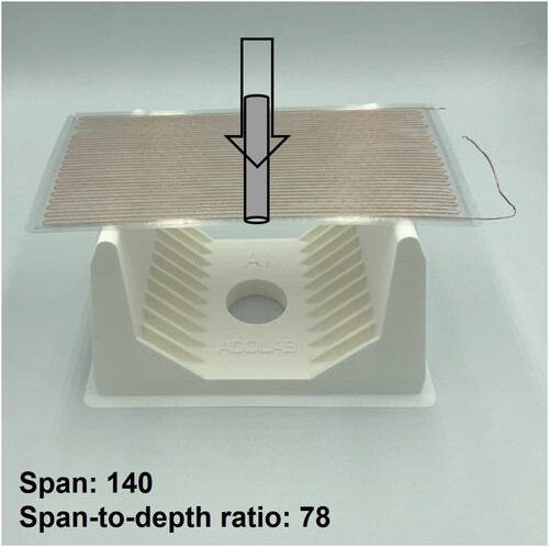
The BK2840 DC Resistance Meter (B&K Precision Corp., Yorba Linda, CA, USA), comprising of an accuracy of 0.1%, was used to conduct electrical resistance measurements as a function of controlled mid-span deflections. The specimens were deflected at the mid-span with an increment of 0.1 mm (accuracy of 0.03%) as shown in and . Force (accuracy of ±0.05 N) and electrical resistance measurements were taken at each mid-span deflection increment in a static state. Sampling time was 402 milliseconds.
The sensitivity coefficients, kp and kD, were estimated according to Eqs. (1) and (2).
(1)
(1) ΔR is the difference between the final and initial resistance, Ri is the initial resistance, P is the force (N) at the mid-point of the load-deflection curve, and kp is the force sensitivity coefficient.
(2)
(2) D is the deflection (mm) of the centerline of the test specimen at the middle of the support span and kD is the deflection sensitivity coefficient. Considering the large support spans of the test specimens, the flexural stress, σf (MPa), in the outer surface of the test specimen at the mid-span is estimated using Eq. 3 as follows:
(3)
(3) where L is the support span (mm), b is the specimen width (mm), and d is the specimen thickness (mm). The flexural strain, ϵf, in the outer surface of the test specimen at the mid-span is calculated according to Eq. 4 as follows:
(4)
(4)
Results
All specimens were successfully manufactured using the parameters listed in and . shows the dispensation of CCW and CCF, and the end-use Type B specimens. and show the raw results of self-sensing under flexural loads for Type A and Type B specimen embedded with CCW. Similarly, and depict the results for specimens embedded with CCF. shows the linear fit of the fractional change in resistance as a function of force and deflection at mid-span for both test specimens Type A and B. lists the piezoelectric properties of the test specimens based on statistical evidence. denotes the flexural stress–strain curves for both test specimens types, i.e. Type A and Type B, comprising of copper wire and carbon fiber.
Figure 5. Additive manufacturing of Type B specimen with (a) continuous copper wire and (b) continuous carbon fiber, and (c) the end-use specimens.
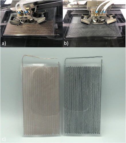
Figure 6. Self-sensing capability of Type A specimen embedded with CCW.
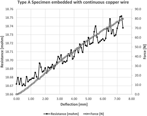
Figure 7. Self-sensing capability of Type B specimen embedded with CCW.
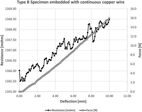
Figure 8. Self-sensing capability of Type A specimen embedded with CCF.
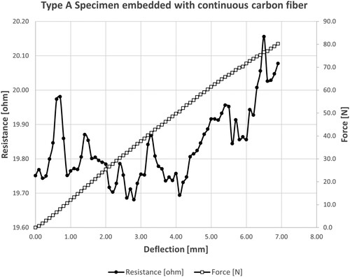
Figure 9. Self-sensing capability of Type B specimen embedded with CCF.
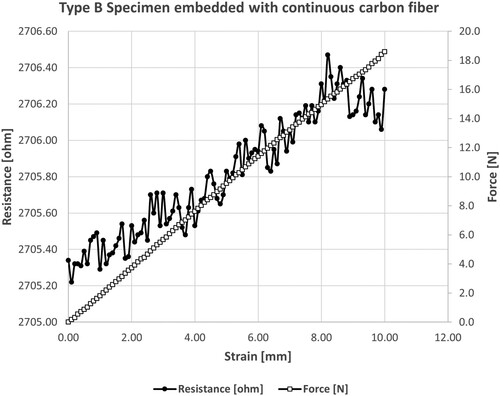
Figure 10. Linear regression of fractional change in electrical resistance as a function of force and deflection for Type A and Type B specimens. (a)Type A: CCW (b)Type B: CCW (c)Type A: CCF (d)Type B: CCF
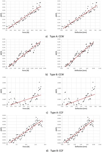
Figure 11. Flexural stress in the outer surface at midpoint as a function of flexural strain.
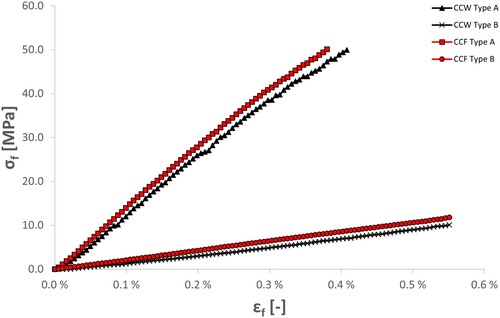
Table 3. Piezoelectric properties of the test specimens based on statistical evidence.
Discussion
This study develops and evaluates self-sensing capabilities of additively manufactured parts. A prerequisite for this work was the establishment of stable processing parameters for embedding CCW. The trial and error approach successfully yielded processing parameters for embedding CCW using a commercially available AM machine.
As shown in , the identified processing parameters allow for embedding CCW in a freeform manner within each layer of the print comprising of an amorphous thermoplastic polymer (PETG) matrix. The Z-lift on restart (mm) ensured that the CCW extruder was adequately raised to extrude the copper wire before printing. The default value of 0.5 mm of Z-lift on restart was inadequate to extrude the CCW owing to higher stiffness of CCW compared to CCF. Higher values than 1 mm can curl the tail of the CCW upon initiation of the print. The fiber extrusion speed was decreased to 1 mm/s to ensure that an accurate polygon was printed with adequate adhesion to the underlying layer. High fiber extrusion speed can cause entanglement of the CCW in the fiber feeder of the machine. The restart pause (sec) is the delay before the initiation of CCW printing. This was significantly increased to 25 sec from the default value of 1 sec to ensure that the tail of CCW adhered to the underlying layer. The fiber feed rate (%) was increased by 25% to decrease the tension in the CCW. This ensured adequate fitting of the CCW to the presumed path length. Finally, the printing speed coefficient was decreased by 40% to compensate for the fiber extrusion speed and to allow adequate printing of the CCW. A total of 20 test samples were printed to identify these printing parameters. Though these parameters ensure a stable process for printing CCW, there is an opportunity for further optimisation for future work.
Following this novel capability, two types of test specimens, i.e. Type A and Type B, were printed with CCW. Specimens embedded with CCF were printed in parallel using the machine’s default processing parameters as reference. For Type B, the length and width of the specimens were increased by three times compared to Type A. Subsequently, two flexural fixtures were designed and manufactured with three folds difference in span-to-depth ratios for fair comparison with identical flexural stress projection at the mid-span of the test specimens. Type A specimen was force-oriented because it had a smaller support span enabling higher loads as a function of deflection. Comparatively, Type B specimen was strain-oriented because it allowed for increased deflection with lower loads. Further, Type B allowed for evaluating the difference between greater number of CCW and CCF grid lines. This novel test setup allowed for measuring the electrical resistance of CCW and CCF embedded within the test specimens as the specimens were deflected at the midspan.
In line with the hypothesis, electrical resistance within the embedded elements increased as the deflection was incrementally increased, confirming that both CCW and CCF can be used to establish self-sensing capabilities in additively manufactured parts. Though the literature has highlighted the ability to embed CCF for self-sensing applications [Citation30], the novelty of this work extends to embedding CCW using a commercially available system for self-sensing applications. Further, it extends the self-sensing capabilities from single-grid to multi-grid design configuration considering also the CCF specimens. The results indicate that electrical resistance increases as the deflection causes the embedded elements to undergo deformation, which reduces the cross-sectional area of both wire and fibers. This is because electrical resistance is inversely proportional to the cross-sectional area following Ohm’s law.
The results of both specimens, i.e. Type A and B, embedded with CCW confirm that electrical resistance increases linearly as a function of force and deflection, as shown in (a and b). The increase in resistance range from specimen Type A to B was quite identical (95%) to the increase in number of grid lines i.e. from 1 to 38. The coefficients of determination of sensitivity coefficients, shown in for both Type A and Type B, indicate a strong linear relationship (R-squared > 93.8%) with significant results (p-value < 0.005). Specimen Type A sustained the linear relationship with flexural stress of 49.9 MPa at a flexural strain of 0.4%, as shown in . Whereas Type B specimen was able to reach identical flexural strain at only 5.9 MPa of flexural stress. Considering the size of the test specimens, the sensitivity tolerance for all CCW specimens was reasonable (< ± 3.0%) compared to conventional strain gauges that typically have a sensitivity tolerance of about 1% at the cost of miniaturised size. This noise, shown by subsequent peaks and troughs in and , is most likely due to the external disturbances when the force is exerted onto the specimens, which causes fluctuations in contact between the crocodile clips and electrodes.
Similarly, the results of CCF specimens also confirm the increase in electrical resistance as a function of force and deflection, as shown in (c and d). The change in resistance of CCF Type A specimen exhibits a pattern of steep rise followed by sharp falls as shown in . This is caused by high flexural stress applied at the mid span. This specimen was loaded with up to 50.1 MPa of flexural stress exhibiting 0.4% of flexural strain. As the flexural stress at the mid-point is increased, it most likely facilitates the detachment of the ultrathin monofilaments of the CCF from the impregnated thermo-active binder that the original equipment manufacturer uses to create the tow of filament. Luan et al. [Citation30] have reported an identical phenomenon. Though the overall electrical resistance increases, the goodness of fit is poor (R-squared < 35.3.0%) and the sensitivity tolerance is high (< ± 17.47%), as shown in . This can also be explained by the wavy pattern of dispensation of CCF, which contains many ultrathin monofilaments, as opposed to CCW, which contains only one monofilament, as shown in . In contrast, CCF Type B shows a strong linear relationship (R-squared > 90.7%) with reasonable sensitivity tolerance of ±3.2%. The force sensitivity coefficient, Kp (21.3 × 10⁻⁶ × N−1), estimated in this study is on the reasonable range compared to the study conducted by Luan et al. [Citation30], which indicates a force sensitivity coefficient of 11.2 × 10⁻⁶ × N−1, considering the differences in specimen dimensions, support span, and thermoplastic matrix. As shown in and , an identical peak-to-trough amplitude is observed in Type B specimen compared to Type A. This is because identical flexural stress projection was applied for both specimen types. However, this phenomenon seems to be localised in Type B owing to a higher number of grid lines, i.e. 38, compared to 1 for Type A specimen.
Considering deflection as the stimulant, the force-oriented specimen Type A yielded higher deflection sensitivity coefficients compared to Type B. Considering force as the stimulant, the strain-oriented specimen Type B incurred higher force sensitivity coefficients compared to Type A. This is logical because higher coefficients are needed to cover a smaller range. The results of CCF Type A indicate that the span-to-depth ratio of 26 is too small considering only one grid line of the used CCF. Additional grid lines should be added to mitigate non-linearity. In general, the sensitivity coefficients of the test specimens were higher (x 5-6) for CCW compared to CCF for Type B specimens.
The outcomes of the results serve as a proof of concept that embedding CCW and CCF can enable self-sensing capabilities in additively manufactured parts. The results confirm that sensitivity coefficients can be tuned for personalised applications. This opens a vast number of opportunities and a direction for both practical applications and future research work. For example, this work allows condition monitoring of custom-designed end-use parts considering the geometric freedom that AM offers. Creating customised patterns of the conductive elements can allow for monitoring stresses and strains at different regions of the part to detect forces exerted on specific projections. The self-sensing capabilities can be extended to temperature, radio-waves, and damage-specific stimuli. The CCW also circumvents the limitations caused by poor conductivity and shorting issues that are highlighted by Espalin et al. [Citation21]. In conjunction with semi-passive and active sensors, it can yield interconnects. The CCW and CCF can also be printed on the exterior surfaces of the parts. Continuous conductive elements can also act as output transducers to provide heat and magnetic flux to the part and its surrounding. A simple wheatstone bridge configuration can allow for detecting miniscule changes in resistance. The current study is limited to embedding CCW and CCF in one layer, future work is needed to join the conductive elements in multiple layers, for example through external or internal interconnects in the z-axis of the print.
Conclusion
Implementing additive manufacturing in an industry 4.0 setting requires tools that allow self-sensing properties for big data collection, analysis, and evidence-based decision-making without compromising the functional integrity of the end-use part. Facilitating the interface between physical and digital environments, this study develops and examines the self-sensing capability of additively manufactured parts embedded with continuous copper wire and continuous carbon fiber under flexural loads. To this end, a stable printing process was developed for embedding copper in an amorphous thermoplastic matrix using a commercial material extrusion-based machine. Tailor-made specimens and setups were devised to test the self-sensing capabilities. The outcomes of regression models yielded significant results, confirming highly dependent relationship between electrical resistance as a function force and deflection. The work allows researchers and practitioners to create self-sensing smart parts for condition monitoring, machine learning, and preventive maintenance required for industry 4.0.
Disclosure statement
No potential conflict of interest was reported by the author(s).
Data availability statement
The data that support the outcomes of this study are available from the corresponding author upon reasonable request.
Additional information
Funding
References
- Akmal JS, Salmi M, Björkstrand R, et al. Switchover to industrial additive manufacturing: dynamic decision-making for problematic spare parts. Int J Oper Prod Manage. 2022;42(13):358–384. doi: 10.1108/IJOPM-01-2022-0054
- ISO/ASTM 52900. ISO/ASTM 52900:2021(en) additive manufacturing – general principles – terminology. 2nd ed. Geneva: ISO/ASTM International 2015; 2021.
- Baumers M, Holweg M. On the economics of additive manufacturing: experimental findings. J Oper Manage. 2019;65(8):794–809. doi: 10.1002/joom.1053
- Hague R, Mansour S, Saleh N. Material and design considerations for rapid manufacturing. Int J Prod Res. 2004;42(22):4691–4708. doi: 10.1080/00207840410001733940
- Kukko K, Akmal JS, Kangas A, et al. Additively manufactured parametric universal clip-system: an open source approach for aiding personal exposure measurement in the breathing zone. Appl Sci. 2020;10(19):6671. doi: 10.3390/APP10196671
- Akmal J, Macarie M, Björkstrand R, et al. Defect detection in laser-based powder bed fusion process using machine learning classification methods. IOP Conf Ser: Mater Sci Eng. 2023;1296(1):012013, doi: 10.1088/1757-899x/1296/1/012013
- Araújo N, Pacheco V, Costa L. Smart additive manufacturing: the path to the digital value chain. Technologies. 2021;9(4):88, doi: 10.3390/technologies9040088
- Bi K, Lin D, Liao Y, et al. Additive manufacturing embraces big data. Prog Addit Manuf. 2021;6(2):181–197. doi: 10.1007/s40964-021-00172-8
- Wang L, Alexander CA. Additive manufacturing and big data. Int J Math Eng Manage Sci. 2016;1(3):107–121. doi: 10.33889/ijmems.2016.1.3-012
- Akmal JS, Salmi M, Mäkitie A, et al. Implementation of industrial additive manufacturing: intelligent implants and drug delivery systems. J Funct Biomater. 2018;9(3):41. doi: 10.3390/jfb9030041
- Binnard M. Design by composition for rapid prototyping. New York: Stanford University; 1999.
- Cham JG, Pruitt BL, Cutkosky MR, et al. Layered manufacturing with embedded components: process planning considerations. Proceedings of the ASME design engineering technical conference. 1999;4:93–101. doi: 10.1115/DETC99/DFM-8910
- Kataria A, Rosen DW. Building around inserts: methods for fabricating complex devices in stereolithography. Rapid Prototyp J. 2001;7(5):253–261. doi: 10.1108/13552540110410459
- Prinz FB, Weiss LE. Novel applications and implementations of shape deposition manufacturing. Nav Res Rev. 1998;50:19–26.
- Akmal JS. Switchover to additive manufacturing: dynamic decision-making for accurate, personalized and smart end-use parts. Helsinki: Aalto University; 2022.
- Feldhausen T, Yelamanchi B, Gomez A, et al. Embedding ceramic components in metal structures with hybrid directed energy deposition. Int J Adv Manuf Technol. 2023;125(9–10):4425–4433. doi: 10.1007/s00170-023-10812-8
- Castillo S, Muse D, Medina F, et al. Electronics integration in conformal substrates fabricated with additive layered manufacturing. 20th annual international solid freeform fabrication symposium, SFF 2009. 2009;730–737.
- Gutierrez C, Salas R, Hernandez G, et al. Cubesat fabrication through additive manufacturing and micro-dispensing. 44th international symposium on microelectronics 2011, IMAPS 2011. 2011;2:1021–1027. doi: 10.4071/isom-2011-tha4-paper3
- Lopes AJ, MacDonald E, Wicker RB. Integrating stereolithography and direct print technologies for 3D structural electronics fabrication. Rapid Prototyp J. 2012;18(2):129–143. doi: 10.1108/13552541211212113
- Martinez AC, Schiaffino EM, Aranzola AP, et al. Multiprocess 3D printing of sodium-ion batteries via vat photopolymerization and direct ink writing. J Phys Energy. 2023;5(4). doi: 10.1088/2515-7655/acf958
- Espalin D, Muse DW, MacDonald E, et al. 3D printing multifunctionality: structures with electronics. Int J Adv Manuf Technol. 2014;72(5–8):963–978. doi: 10.1007/s00170-014-5717-7
- Kim C, Espalin D, Cuaron A, et al. Cooperative tool path planning for wire embedding on additively manufactured curved surfaces using robot kinematics. J Mech Robot. 2015;7(2). doi: 10.1115/1.4029473
- Saari M, Cox B, Richer E, et al. Fiber encapsulation additive manufacturing: an enabling technology for 3D printing of electromechanical devices and robotic components. 3D Print Addit Manuf. 2015;2(1):32–39. doi: 10.1089/3dp.2015.0003
- Shemelya C, Cedillos F, Aguilera E, et al. Encapsulated copper wire and copper mesh capacitive sensing for 3-D printing applications. IEEE Sens J. 2015;15(2):1280–1286. doi: 10.1109/JSEN.2014.2356973
- Anisoprint Sarl. Continuous fiber 3D printing for manufacturing of optimal composites; 2020. https://anisoprint.com/.
- Markforged. Industrial additive manufacturing platform | Markforged; 2022. https://markforged.com/.
- Bashmal S, Siddiqui M, Arif AFM. Experimental and numerical investigations on the mechanical characteristics of carbon fiber sensors. Sensors. 2017;17(9). doi: 10.3390/s17092026
- Elimat ZM, Hussain WT, Zihlif AM. PAN-based carbon fibers/PMMA composites: thermal, dielectric, and DC electrical properties. J Mater Sci: Mater Electron. 2012;23(12):2117–2122. doi: 10.1007/s10854-012-0712-y
- Kumar SS, Akmal JS, Salmi M. 4D printing of shape memory polymer with continuous carbon fiber. Prog Addit Manuf. 2023. doi: 10.1007/s40964-023-00553-1
- Luan C, Yao X, Shen H, et al. Self-sensing of position-related loads in continuous carbon fibers-embedded 3D-printed polymer structures using electrical resistance measurement. Sensors. 2018;18(4). doi: 10.3390/s18040994
- Saifeldeen MA, Fouad N, Huang H, et al. Advancement of long-gauge carbon fiber line sensors for strain measurements in structures. J Intell Mater Syst Struct. 2017;28(7):878–887. doi: 10.1177/1045389X16665974
- ASTM. D790-03-standard test method for flexural properties of unreinforced and reinforced plastics and electrical insulation materials (Patent D 790–03). ASTM Standards (D 790–03); 2015.