
 ?Mathematical formulae have been encoded as MathML and are displayed in this HTML version using MathJax in order to improve their display. Uncheck the box to turn MathJax off. This feature requires Javascript. Click on a formula to zoom.
ABSTRACT
3D concrete printing (3DCP) has attracted significant attention due to the benefits of enhanced productivity and sustainability. However, existing 3DCP techniques face challenges of automation and practicality in integrating conventional rebar reinforcement with printed concrete structures. This study presents an automated robot system coupled with Building Information Modeling (BIM) to address the challenge. Dynamo scripts in BIM were used to generate printing paths, further optimised by a proposed algorithm for incorporating rebar reinforcement. A deep learning model was adopted to identify rebars with large aspect ratios. The average accuracy of rebar recognition is 92.5%, with a position error within 2 mm. A centralised control system was developed for multiple-device communication, including a camera, a robot arm, and a gripper. Finally, a real-time demonstration was conducted, representing the first practical demonstration of an automated robotic system to integrate rebar reinforcement with printed structures using BIM-generated data in the physical world.
1. Introduction
3D concrete printing (3DCP) has rapidly developed in the last decades. 3DCP allows for the layer-by-layer creation of concrete structures via a formwork-free process [Citation1]. With the unique characteristics of the construction process, 3DCP can reduce carbon emissions [Citation2], reduce manpower requirements, increase productivity [Citation3], and enhance sustainability [Citation4]. Weng et al. [Citation5] conducted a comparison study to investigate the difference between a printed bathroom unit (PBU) and its precast counterpart with respect to economics, environment, and energy consumption. The results reveal that the PBU built by 3DCP can achieve a reduction of 25.40% in cost, 85.90% in CO2 emissions, and 87.10% in energy consumption.
A critical hindrance to the wider adoption of 3DCP is the challenge of incorporating conventional rebar reinforcement with a printed concrete structure [Citation6]. Many previous studies adopted manual installation of steel reinforcement during or after the printing process [Citation7,Citation8]. The main limitation of these methods is the lack of automation since the labour-intensive manual operations are required. To tackle the automation problem, the solution using continuous steel cable [Citation9] and 3D printed rebar [Citation10] are proposed. However, these methods provide limited mechanical enhancement in structural applications compared to the traditional rebars [Citation11]. Therefore, finding a solution to achieve the automation of the entire process, including concrete printing and rebar integration, remains a critical challenge.
Based on the detailed literature review of existing studies in Section 2, the integration of Building Information Modelling (BIM) and robotic arm with 3DCP is a possible solution. To fill the research gaps, three research challenges need to be addressed: 1) how to generate accurate printing paths and rebar-related data for the control of the printing process, 2) how to acquire accurate positions and orientations of rebars for controlling the rebar picking-up and placement process, 3) how to achieve flexible robot manipulation control for different task planning.
To address these challenges, this study aims to develop a BIM and robotic arm-integrated system for the achievement of automated and synchronised concrete printing and rebar installation. Self-developed Dynamo scripts in the BIM platform can extract the geometrical and material data of both concrete and rebars. These data are used to generate a collision-free printing path and to instruct the manipulation of the robotic arm for various tasks (e.g. rebar picking up and placement). An enhanced deep-learning computer vision model is trained to detect the position and orientation of rebars with a large aspect ratio. The Robot Operation System (ROS) was employed to achieve communication among multiple devices, including a camera, a gripper, and a robotic arm.
The remainder of this paper is organised as follows. In Section 2, the existing reinforcement methods, and the integration of BIM and robot arm for construction tasks are reviewed and summarised to emphasise research gaps. Section 3 introduces the framework and methodologies. Section 4 presents a demonstration in the physical world, and the experimental results are discussed. In Sections 5 and 6, discussions and conclusions of this work are provided, and future works are sketched.
2. Literature review
2.1. Rebar reinforcement in printed structures
The field of 3DCP offers various rebar reinforcement methods, including pre-installed reinforcement, which involves manually placing conventional rebars [Citation4,Citation5]; in-process reinforcement, where continuous micro-cables [Citation9,Citation12] are added, or steel meshes [Citation13] are introduced; and post-installation reinforcement [Citation8]. Although each method has its unique characteristics, they all face common challenges with respect to automation and its practical application in engineering. Firstly, the pre-installation reinforcement method used by Huashang Tengda [Citation14] involves manually placing rebars before concrete deposition and utilises a dual-nozzle system to deposit concrete through the rebars. However, this approach heavily relies on manual operation, which limits its efficiency and practicality. The manual rebar placing method is labour-intensive and incompatible with the automated process of 3DCP [Citation5].
Baz et al. [Citation7] proposed an in-process reinforcement method, focusing on installation of traditional rebars during concrete deposition. Another similar approach involves using pre-bent traditional rebars for reinforcing 3D printed structures [Citation15]. However, both of these methods lack automation, posing challenges for large-scale implementation. To address the automation issues, researchers have suggested the use of micro-cables and printed rebar reinforcement, where micro-cables are driven by gears [Citation9,Citation12]. Micro-cables were embedded into the concrete by a fully automated process, and the results show that the flexural performance of reinforced specimens was improved. However, using micro-cables as the reinforcement is inadequate for the structural application [Citation16]. Wire Arc Additive Manufacturing (WAAM) was used by Mechtcherine et al. [Citation10] to build up the reinforcement by a laser welding method. However, the WAAM method faces constraints such as high energy costs and the potential of affecting material properties.
In the post-installed reinforcement, Zhu et al. [Citation8] investigated the compressive behaviour of reinforced columns with printed formwork and post-installed reinforcement. The results show that the reinforced columns exhibit higher stiffness and loading bearing capacity compared to that of the casting counterpart. Post-installed reinforcement is also used in the printed concrete modules, which are assembled subsequently. Steel reinforcement is then installed and bonded by fresh concrete as the structural reinforcement for the enhancement of structural performance [Citation17]. Nevertheless, similar to the other methods, this approach also lacks automation.
In summary, these rebar reinforcement methods significantly improve the mechanical properties of 3D printed concrete structures. However, the primary limitations of the existing studies are lack of automation when tackling practical challenges in engineering implementation.
2.2. Integration of BIM and robotic for construction tasks
The BIM technique has been widely applied in the construction field, which integrates advanced technologies such as robotics and artificial intelligence to facilitate the automation of conventional construction sector [Citation18]. BIM is a digital representation of a building and a data-sharing platform that contains detailed information on design, construction, and maintenance processes [Citation19]. In practice, BIM is usually employed for information storage, management, and processing the models [Citation20–22]. Additionally, BIM is an efficient tool for the operation of construction robotics. For instance, BIM can be used to generate the accurate and explicit information as input for the robots to reliably perform the designated tasks [Citation23,Citation24]. Integrating BIM, ROS, and robotics, the entire system can facilitate construction robot task planning and simulating in the virtual environment for various construction tasks [Citation25], such as building inspection [Citation26], visual installation progress monitoring [Citation27], wood frames [Citation23] and bricks assembly [Citation18], façade installation [Citation28], etc.
Nevertheless, the existing literature focusing on the integration of BIM, robotics, and 3DCP for the installation of rebar reinforcement in 3DCP is still lacking. Studies have leveraged BIM data processing capabilities to automatically generate toolpath for 3DCP [Citation11,Citation29]. However, to achieve rebar reinforcement installation by an integrated system of BIM, robotics, and 3DCP, as well as implement the system in the physical world, there are still many challenges, including collision free toolpath generation, rebar identification, and in-process communication. With respect to the collision free toolpath generation, the previous work of the author has conducted a preliminary work to generate collision free toolpath for the avoidance between rebars and printed concrete [Citation11], and a similar methodology will be adopted in this work.
With respect to rebar reinforcement data, it is a challenge to identify an individual rebar with a large aspect ratio in the physical world. Existing studies on the rebar identification mainly focus on position estimation [Citation30], counting rebars through cross-section images [Citation31], diameter and spacing detection [Citation32], visualising the estimations of rebar spacing and concrete cover [Citation33], etc. However, the individual rebar used in this system for the installation of reinforcement generally have a large aspect ratio, more than 40:1 (length: diameter), which results in the challenge on the accurately object detection and identification, since the entire object is hard to be identified by the computer vision method accurately and efficiently in the real-time operation [Citation34,Citation35].
With respect to the in-process communication between multi-devices for a synchronised construction task by robotics, the main challenge for this work is to achieve the communication between the image data obtained by a camera and ROS for a real-time task planning. Existing study on the integration of ROS and robotics for construction tasks mainly focusing on simulation and operation without the communication between the data of working environment and ROS for a real-time task planning. For instance, the ROS was adopted for the simulation of constructions tasks based on the data from pre-designed BIM, the assembly of modular components from pre-designed BIM data [Citation36], etc. In the real work environment, the rebars or other targets may be placed randomly, and therefore, it is necessary to obtain real-time data for the real-time task planning.
In summary, motivated by the abovementioned research gaps, three new methods are adopted in this work. Firstly, the developed method in the existing literature for the toolpath generation with respect to a concrete structure with rebar reinforcement will be adopted [Citation11]. With this method, the collision free toolpath can be generated from a BIM model for the achievement of the avoidance between rebars and printed concrete materials. Secondly, the computer vision method based on YOLOv5 with the benefits of high stability and accuracy will be adopted to enhance object detection for a rebar with a large aspect ratio. Thirdly, in the proposed method, the data acquisition, processing, conversion, and communication method is proposed to achieve the real-time task planning of robotics based on the real-time data of work environment obtained by the computer vision.
3. Methodology
3.1. System framework
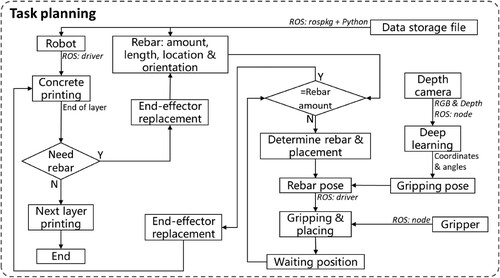
shows the overall framework of the proposed system. The system consists of BIM data processing and robotic arm manipulation functions. In the BIM data process function, concrete data was adopted for printing path generation, and the rebar data was used for printing path optimisation and robotic manipulation control. After the BIM data process, the concrete and rebar data were stored in a file via Excel.WriteToFile in Dynamo [Citation37] and the stored data were adopted for robot manipulation control by the ROS rospkg library and the Python standard library [Citation38] in the robotic manipulation function. For the enhancement of robot operation in the robotic manipulation function, a deep-learning computer vision model that can detect rebars with a large aspect ratio was adopted for the automatic detection of rebar position and orientation.
Figure 1. Overview of the proposed system framework.
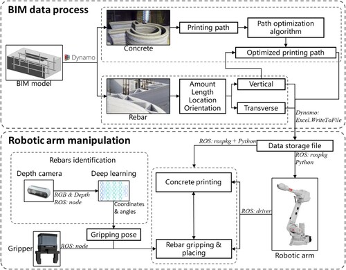
Task planning was conducted to manipulate the motion trajectory of a robotic arm to achieve 3DCP and rebar placement in the physical demonstration. The robotic arm was equipped with a concrete extruder and a rebar gripper for concrete printing and rebar placement, respectively. A ROS was adopted to achieve seamless communication and collaborative control among the camera, the gripper, and the robotic arm [Citation39,Citation40]. Finally, the proposed system was validated by a lab-scale demonstration in the physical world.
3.2. BIM data process
shows the BIM data process function, which is adopted to generate the concrete printing path and obtain geometric data of rebars by a self-developed script in Dynamo. Autodesk Revit and Dynamo are used for modelling and data processing, respectively. Dynamo is a visual programming environment where parametric design is achieved by connecting multiple functional nodes to form the programming logic [Citation41,Citation42].
Figure 2. The workflow for the BIM data process.
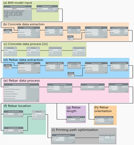
As shown in , the BIM data process function consists of eight steps, including BIM model input, extraction, and process of concrete data for printing path generation, extraction and process of rebar data for printing path optimisation, and robotic manipulation control. (a – c) are used for the concrete data process to generate the printing path. Firstly, a BIM model of a reinforced concrete structure is designed in Revit ( a). The process method of concrete data was proposed and validated by Weng et al. [Citation43], and the method allows for the automatic generation of a continuous printing path by meshing, slicing, point-reordering, and G-code generation ( b and c).
(d – h) are used for the rebar data process to obtain the rebar length, location, and orientation. (d) is used to extract the rebar data based on rebar types in the BIM model, such as the HRB400 in this study. The rebar data is then converted from a BIM element to a geometric curve using the Rebar.GetCenterLineCurve node ( e), followed by obtaining the coordinates of the start and end points of the curve using the Curve.StartPoint and Curve.endpoint nodes, respectively ( f). To obtain the location of rebars for robot gripping, a self-developed Python node Midpoint is employed to calculate the centroid coordinates. Finally, the length and orientation of the rebar can be obtained using the Curve.Length node ( g) and Curve.TangentAtParameter node ( h), respectively.
(i) is used to optimise the concrete printing path for collision avoidance. The method in [Citation43] is limited by processing the structure with rebar reinforcement. The rebar position and printed filament may overlap [Citation11]. proposed a new method to address the limitation by considering the geometric relation between printing path and rebar diameter, as shown in (a). The overlap between rebar and printed filament can be avoided with the following relation being achieved:
(1)
(1) where
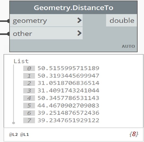
is the distance (mm) between the centre point of the rebar and the infill printing path. R and Wextrusion are rebar radius (mm) and the extrusion width of printed filament (mm), respectively. Equation (1) was adopted for the optimisation of the printing path. The distance of each vertical rebar to the generated infill printing path is calculated based on the obtained rebar location by Geometry.DistanceTo node. Then, the algorithm of printing path optimisation is designed by projecting the rebar into the inner control line, followed by using the projected point as a new control point to generate a new collision-free infill path, as shown in (b).
Figure 3. Printing path optimisation. (a) Geometric relation between vertical rebars and printed infill filaments; (b) Schematic of infill path optimisation. (With permission from HKIE Transaction) [Citation11].
![Figure 3. Printing path optimisation. (a) Geometric relation between vertical rebars and printed infill filaments; (b) Schematic of infill path optimisation. (With permission from HKIE Transaction) [Citation11].](/cms/asset/cc901c85-ceb0-4b84-b2df-e193581eeaf5/nvpp_a_2332423_f0003_oc.jpg)
3.3. Robotic arm manipulation
The robotic arm in this study is manipulated by pose control, including the control of position and orientation [Citation44]. The pose data for concrete printing and rebar placement is obtained through the BIM data process, as mentioned in Section 3.2. The gripping poses of the rebars by the robotic arm are obtained by a depth camera with a YOLO-based detection network, which can detect an object with a large aspect ratio of 40:1 [Citation45].
The robotic manipulation is planned based on the concrete printing path and rebar position of the BIM model. Firstly, the robotic arm manipulation system is built, and the transformation relationship between coordinate systems is presented. An improved detection network for a rotating target with a large aspect ratio is then introduced to obtain the gripping pose of the robotic arm. Afterward, a manipulation task planning is introduced to achieve concrete printing and rebar placement with a robotic arm. An auxiliary gripping accessory was designed for the gripper in this work to enhance the stability of rebar gripping and placement. The detailed robotic arm manipulation is discussed below.
3.3.1. System setup and coordinate transformation
shows the system setup and coordinate systems used in this work. The devices involved in this study are a robotic arm, a depth camera, a concrete extruder, and a gripper. The depth camera is employed to provide distance data for vision-based rebar pose identification, the gripper is used to grip and place the rebar, and the concrete extruder is used for 3DCP. The robotic arm is used for concrete printing and rebar placement. The overall size of the device is approximately 1.7 m × 1.65 m × 2.65 m.
Figure 4. System setup and coordinate systems. (a) System setup and eye-to-hand calibration experimental layout; (b) Extruder and coordinate system; (c) Gripper and coordinate system.
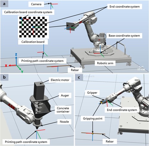
The robotic arm is manipulated based on the pose control, in which the transformation relation among multi-devices is required. (a) shows the eye-to-hand calibration [Citation46], which is adopted to obtain the transformation relation between the camera and the robotic arm. The transformation matrix of the camera coordinate system to the robotic arm base coordinate system can be defined as:
(2)
(2) where
represents the transformation matrix of the camera coordinate system and the calibration board coordinate system obtained by camera calibration.
represents the transformation matrix of the calibration board coordinate system and the robotic arm end coordinate system, which is obtained by the calibration board size and a simple rotation transformation.
represents the transformation matrix of the robotic arm end coordinate system to the base coordinate system, which is obtained by the joint angles and D-H parameters of the robotic arm [Citation47]. Define the robot arm base coordinate system to overlap with the world coordinate system:
(3)
(3) where
represents the transformation matrix of the camera coordinate system to the world coordinate system.
represents the orientation transformation matrix of the camera coordinate system to the world coordinate system.
represents the position of the camera coordinate system origin in the world coordinate system.
The printing paths and rebar placement coordinates generated by the BIM are within the printing path coordinate system. The printing path coordinate system is dynamic, where the geometric centre point of the first layer path is defined as the origin of the printing path coordinate system. The size of the model and the working range of the robotic arm need to be considered when defining the origin of the printing coordinate system. The transformation matrix of the printing path coordinate system to the robotic arm end coordinate system is . The transformation matrix of the printing path coordinates to the world coordinate system is:
(4)
(4) Concrete printing is layer-atop-layer. Thus, the orientation of the printing path in the X-direction is defined by the path generated in the BIM, and the orientation in the Z-direction is vertical down. The rebar placement positions generated by BIM are within the printing path coordinate system. Due to the limitation of the two-finger gripper, the placement orientation of the X-direction of the rebars is defined by the positions generated by the BIM, and the orientation of the Z-direction is the direction away from the robotic arm to the coordinates of the corresponding rebars. The gripping point is at 155 mm in the Z-axis of the robotic arm end coordinate system in this work.
3.3.2. Deep learning-based rebar gripping pose
With the built system setup and coordinate system, an improved detection network for a rotating target with a large aspect ratio is then introduced to obtain the gripping pose of rebars. In our application scenario, which involves real-time and accurate detection of rebars with a large aspect ratio, the network is required to possess precision, speed, real-time performance, and customisability. Tan et al. [Citation48] compared the performance of YOLO, Faster R-CNN, and SSD, finding that YOLO exhibited superior mean Average Precision (mAP), a critical factor for accurately identifying rebars with complex surface shapes. Additionally, Li et al. [Citation49] demonstrated that YOLO processes data over eight times faster than Faster R-CNN while maintaining a high mAP (80.17%), a rapid response capability essential for real-time detection and feedback of rebars. The low latency of YOLO, due to its single convolution process, simplifies and accelerates the processing without sacrificing accuracy [Citation50].
Furthermore, traditional networks predict bounding boxes aligned with the coordinate axes [Citation31], which are inadequate for accurately representing the orientation of rebars with a large aspect ratio [Citation51]. Yue et al. [Citation52]improved the standard YOLO network, achieving an mAP of 97.38%, which is 3.41% higher than the original YOLO. This indicates that the YOLO network can be effectively customised to meet specific application needs, as also validated by the work of Salman et al. [Citation53] and Sharma et al. [Citation54].
Therefore, this paper is based on the YOLOv5 object detection network, which has been extensively tested and validated [Citation55]. We have modified its axis-aligned bounding boxes to rotating bounding boxes. By encompassing the rebars within these rotating bounding boxes, the aim is to acquire the coordinates and angles of rebars with a large aspect ratio in their rotational orientation. The detection results are combined with coordinate transformations to obtain the gripping pose of the robotic arm. The angle parameter θ is added to the channel of the feature map of YOLOv5. The formula for calculating the initial output channel number in the head of the YOLOv5 network is as follows:
(5)
(5) where 3 represents three bounding boxes predicted for each grid cell, 5 represents the five features of the bounding box
,
,
,
,
, respectively, the
and
coordinates of the centre point, the width and height, and the rotation angle, 1 represents the bounding box confidence score,
represents the number of categories to be recognised by this network.
The rebars have a large aspect ratio and are sensitive to changes in angle. This study employs a Circular Smooth Label (CSL) to increase the tolerance for errors between adjacent angles to address the challenge of discontinuous boundaries in angle regression methods [Citation56]. The CSL formula is as follows:
(6)
(6) where
represents the window function, and the window radius is controlled by r.
The loss function for rotating bounding boxes in YOLOv5 mainly consists of three components: classification loss, bounding box regression loss, and confidence score loss. The classification loss in YOLOv5 for rotating bounding boxes is similar to that of YOLOv5 for horizontal detection. The Intersection over Union (IoU) [Citation57] of the rotating bounding boxes is used as the weighting coefficient when calculating the confidence loss. In this paper, angle regression is treated as a classification task, where the angle loss and bounding box information are treated as independent. Therefore, the loss calculation for rotating bounding boxes involves separately calculating the losses for both the horizontal bounding box and the angle. The bounding box loss is computed with the Complete Intersection over Union (CIoU) loss [Citation58]. The formula to calculate the angle loss function is as follows:
(7)
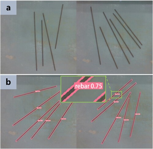
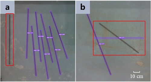
(7) The camera was installed in the position shown in (a), and 1200 images were taken as the training dataset by varying the position of rebars, as shown in (a). The dataset is labelled using roLabelImg [Citation59]. The detection results after training are shown in (b). The rotation angles and pixel coordinates of the endpoints of the rebar bounding box are output by the network. The coordinates of each point on the rebar axis can be calculated from the endpoint coordinates, and thus, all positions of the rebar can be selected as the gripping point.
Figure 5. Detecting rebars with deep learning. (a) Rebars for the training dataset; (b) Rebar detection results.
The position and orientation of the rebar in the world coordinate system need to be obtained and provided to the robotic arm for gripping. The pixel coordinates of the grasping point are transformed to the camera coordinate system based on the camera imaging principle [Citation60], and the coordinate transformation relationship is:
(8)
(8) where
represents the camera depth value of the corresponding pixel point,
represents the camera intrinsic matrix. The rebar coordinates are represented in the world coordinate system:
(9)
(9) The gripper gripping point needs to be coincident with the coordinate of the rebar gripping point when the gripper is gripping the rebar. As shown in (c), the gripping point is at 155 mm in the Z-axis of the robotic arm end coordinate system. The rebar gripping position is:
(10)
(10) The gripper gripping point orientation within the camera coordinate system is represented as:
(11)
(11) where
represents rotating
around the Z-axis of the robotic arm end coordinate system.
represents the transformation matrix of the robotic arm end coordinate system to the camera coordinate system when the origin is coincident. The rebar gripping orientation within the world coordinate system is represented as:
(12)
(12)
3.3.3. Task planning
illustrates the task planning of this system, demonstrating the manipulation of the robotic arm to perform a specific task. The task planning includes concrete printing, rebar placement, data flow, and device coordination control. The robotic arm manipulation is planned for practical operations based on Sections 3.2, 3.3.1, and 3.3.2. The concrete printing path and rebar placement poses are introduced in Section 3.2, and the printing paths and placement poses defined within the printing path coordinate system are introduced in Section 3.3.1. The gripping poses for rebar are introduced in Section 3.3.2. The detailed process is elaborated below.
Figure 6. The manipulation logic of the robotic arm.
Firstly, all ROS nodes of the robotic arm, gripper, and camera are in operational mode, capable of receiving and executing control commands published through the robotic arm console. The printing path coordinate system is defined by the operator based on the model size and the working range of the robotic arm, and the concrete extruder device is assembled as an end-effector of the robotic arm, which is used for concrete material printing. The robotic arm console is ROS-based, utilising Python and the rospkg library to obtain the printing path to manipulate the robotic arm for 3DCP. After each layer of concrete is printed, the system determines whether rebar is needed before the next layer of concrete is printed based on the printing path and rebar position location. If the robotic arm needs to install reinforcement, it will move to the replacement position, which is a specified manual work area outside the working range of the robotic arm, followed by replacing the concrete extruder with the gripper as the end-effector.
Next, the rebar placement poses needed for the current state of the system are obtained from the printing path and rebar position location. The deep learning detection network is activated to obtain the gripping poses of the rebars according to the parameters of the needed rebars. The gripping and placing poses of the rebars are used as control signals to manipulate the robotic arm to complete rebar operation, including gripping, transporting, and placing.
After placing a rebar, the robotic arm returns to the waiting position, where the arm moves out of the camera's field of view to avoid obstruction. At this stage, the procedure determines whether all rebars are placed based on BIM data. If all rebars are installed, the deep learning detection network is deactivated to conserve resources, and the robotic arm is manipulated to move to the replacement position, followed by replacing the end-effector with a concrete extruder. Afterward, the robotic arm is manipulated to move to the start printing point of the next layer based on the printing path until the concrete structure is printed.
Transverse and vertical rebars with different sizes and positions are used in the BIM model of this study. All the rebars were placed in the camera field of view simultaneously. The rebar lengths are calculated based on the bounding box coordinates of the detected rebars to identify the rebar types, followed by determining the appropriate rebar for grasping. The rebars are gripped based on the rebar gripping point coordinates in the order of from the smallest to the largest.
3.3.4. Stability of rebar gripping and placing
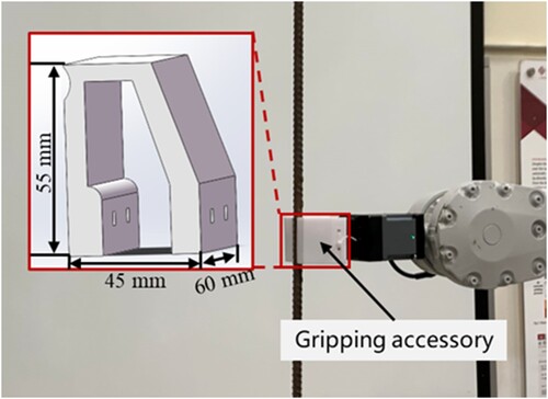
It is critical to maintain stability during rebar gripping and placing since rebar is heavy and has a large aspect ratio. The study designs an auxiliary gripping accessory for the gripper to enhance stability, and the accessory is shown in . Gripping accessory is installed on the gripper. The accessory wraps the rebar with an arc-shaped contour, increasing the contact area with the rebar, which allows for a more uniform application of the gripping force on the surface of the rebar. When subjected to external torque caused by the weight of the rebar, the arc-shaped force distribution evidently enhances the torsional resistance.
Figure 7. Designed gripping accessory to enhance gripping stability.
With respect to the force analysis of the gripping action on the rebar by the gripper, it is necessary to overcome the torque generated by the offset of the rebar's centre of gravity and balance the mass weight of the rebar itself. The force analysis to achieve the condition for the stable holding of the rebar is expressed as follows:
(13)
(13) where
represents the gripping force of the gripper.
represents the coefficient of friction.
represents the actual contact area.
represents the mass weight of the rebar;
represents the distance from the centre of gravity of the rebar to the contact point of the gripper, which is determined by the designated rebar gripping position. According to Equation (13), effective and stable gripping of different rebars is achieved with the gripper by adjusting the gripping force F and contact area A between the accessory and the rebar.
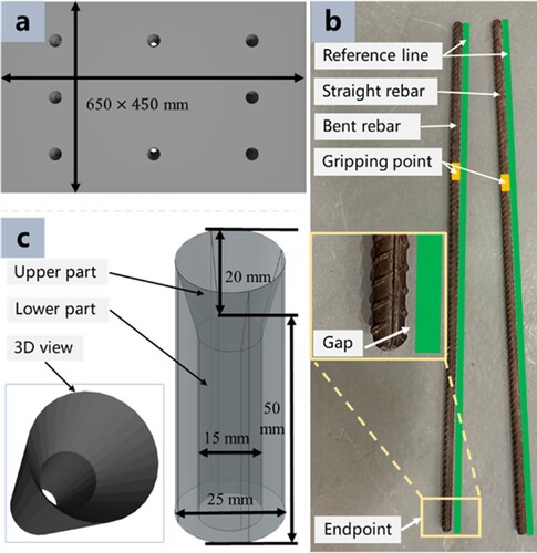
The fabrication of reinforced concrete structures fixes the position of the rebars with the help of some auxiliary supports. In this study a printing base is designed as shown in , which ensures that the vertical rebars remain in the pre-designed vertical position after placement. (a) shows that the holes were fabricated on the printing base according to the vertical rebar coordinate positions. A positioning accuracy problem may be incurred by the bent rebars, which can cause a deviation error in the axis between the rebar gripping point and the endpoint of the rebar when the robot grips the bent rebar from the gripping point instead of the straight rebar, as shown in (b). To tackle the problem, hollow cylinders consisting of upper and lower parts were added to the holes, as shown in (c). The upper part of the inner wall is designed to be curved to allow the bent rebar end to slide into the lower part of the cylinder. The lower part, with an inner diameter 2 mm larger than that of the rebar, is used to hold the vertical rebar in place stably. The gripper accessory and the hollow cylinder are manufactured using polymer 3D printed with polylactic acid material.
Figure 8. Printing base. (a) Printing base with holes; (b) Bent rebar induces deviation error; (c) Designed hollow cylinder.
4. Results
4.1. System setup
shows the system setup in the experimental scenario. Two workstations were used in practical applications: PC1 workstation with Microsoft Windows 11 operating system was used for the BIM data process. In order to achieve file sharing that does not involve network protocols and is highly simple and efficient, PC2 is installed in the VMware virtual machine on PC1. The PC2 with Ubuntu 20.04 operating system was simultaneously connected to the robotic arm control cabinet, camera, and gripper. The control commands were sent to the corresponding devices based on ROS communication. The robotic arm was connected to the workstation through the network cable, the camera and gripper were connected to the workstation through the USB interface, and the concrete extruder device realised extrusion through independently driven motors.
This study developed an advanced communication system, as depicted in , integrating BIM with ROS for the efficient realisation of 3D concrete printing and rebar placement. Within the BIM interface, the automation of model information processing and categorisation was achieved using Dynamo, exporting print paths and rebar coordinate data to a specified shared file in a VMware virtual machine. Subsequently, the ROS interface within the Ubuntu system accesses these files directly, utilising the data to operate various devices, including camera, YOLO network, robotic arm, and gripper, thereby ensuring precise execution of 3D printing and rebar placement tasks.
Figure 9. Communication system between model data and functional nodes.
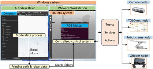
All devices are coordinated through a centralised control system, with each device operating as an individual node. Devices connect to the centralised control system via the message-passing mechanism and standardised communication protocols of the ROS master. Each node focuses on its specific task and interacts with the centralised control system to ensure the consistency of the entire workflow. The centralised control system is capable of real-time monitoring and guiding the operation of the entire system, including extracting the current frame from the image stream, invoking the network to determine the position and orientation of the rebar, and issuing control commands to drive the robotic arm and gripper, thereby executing complex tasks.
ROS-defined standard message types are utilised for inter-node communication, the system ensures data compatibility and uniformity across different nodes. In this context, a single robotic arm is utilised for both concrete printing and rebar placement tasks, with the centralised control system efficiently scheduling the transition of end-effectors based on task requirements, thus guaranteeing workflow continuity and efficacy. In anticipation of future system upgrades or the incorporation of new functional equipment, the centralised control system exhibits remarkable adaptability and flexibility, accommodating additional nodes or refining planning strategies. Overall, this communication system not only guarantees real-time data synchronisation and accurate transmission but also enhances collaborative efficiency among the various devices. The design of this integrated system successfully overcomes the challenges of hardware compatibility and real-time processing capabilities, ensuring the smooth progression of the entire printing process.
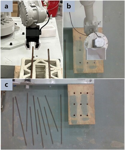
shows the experiment setup. (a) and (b) show the gripper (PGI-140-80), which has a maximum clamping force of 140 N. The gripper can provide real-time feedback to the system on whether the rebar has been grasped or released. (b) shows the concrete extruder used for material printing. (c) shows that the rebars and printing base were placed in the pre-designated position, and the centre point of the printing base is defined as the origin of the printed coordinate system.
Figure 10. Experimental setup. (a) Gripper; (b) Concrete extruder; (c) Rebars and printing base.
In the printing process, the concrete material for printing was Sikacrete-3D with a water-to-power ratio of 0.18. The extrusion speed of the concrete extruder device was set at 1.22 L/min. In the grasping process, the camera (Intel® RealSense™ D435i) continuously captured images at a rate of 8 frames per second. The end-effector speed of the robotic arm (ABB IRB 2600-20/1.65) was set to 0.1 m/s. After the robotic arm completed the gripping in each run, the robotic arm returned to the waiting position to avoid affecting the camera detection field of view before placing the next rebar.
4.2. Physical demonstration
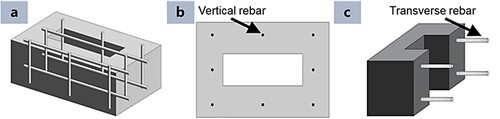
shows the BIM model used for real-time demonstration in the physical world. The BIM model consists of a concrete wall with four transverse rebars and eight vertical rebars ( a). All eight vertical rebars were parallelly installed ( b), and the transverse rebars were designed at two separate positions ( c), located at the height of 30 and 120 mm, respectively. The concrete and rebar data were processed based on the method introduced in Section 3.2.
Figure 11. BIM model. (a) 3D view; (b) Top view; (c) Cross section view.
shows the generated continuous concrete printing path. shows the rebar length, location, and orientation obtained by the Dynamo script. Then, the distance of each vertical rebar to the generated infill path is calculated based on the method introduced in Section 3.2. The width of the printing path and rebar diameter are 20 mm and 10 mm, respectively. As shown in , the minimum distance in this model is 31.05 mm, which satisfies Equation (1). Therefore, no printing path optimisation is required in this study.
Figure 12. Generated concrete printing path.
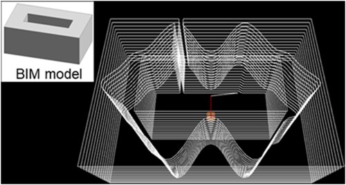
Figure 13. Obtained rebar data from the Dynamo script. (a) rebar locations; (b) rebar lengths; (c) rebar orientations.
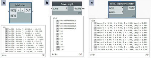
Figure 14. Distance from the vertical rebar to the infill printing path.
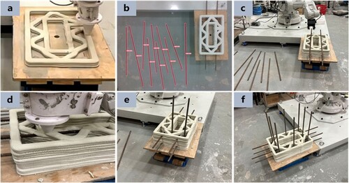
. shows the real-time demonstration in the physical world. Firstly, the robotic arm printed the concrete material based on the concrete printing path from BIM data ( a). When the robot printed the concrete to the height of transverse rebars (30 and 120 mm in this study), the robot stopped its operation, and the rebars were detected by the vision system ( b). Then, the robot gripped and placed the transverse rebars in the designed locations with the required orientations ( c), followed by the printing of the remaining concrete layers ( d). A similar method was adopted for the vertical rebar placement process ( e). The final fabricated physical model is shown in (f). The real-time demonstration video can be found at https://youtu.be/KdJvIELVrlQ. Only one robot was employed in this study, and thus, the concrete extruded was manually replaced with the rebar gripper as the end-effector during the process.
Figure 15. Real-time demonstration in the physical world. (a) Concrete printing; (b) Rebar detection; (c) Transverse rebar placing; (d) Concrete printing; (e) Vertical rebar placing; (f) Completed structure. The video can be accessed at https://youtu.be/KdJvIELVrlQ.
4.3. Results analysis
4.3.1. Performance analysis of network detection
Cross-validation was employed to assess the generalisation ability of the improved YOLOv5 model in this study. Cross-validation offers a balance between operational feasibility and approximating the true distribution of the model. In regression problems, models are typically evaluated by synthesising precision and recall rates. The score is used as a measure, and its formula is given by:
(13)
(13) where
represents precision, and
represents recall. Their formulas are:
(14)
(14) where
,
,
, and
represent true positives, false positives, true negatives, and false negatives, respectively.
An Intersection over Union (IOU) threshold of 0.6 is set, where a detection box is classified as a true positive if the IOU with the ground truth is greater than 0.6; otherwise, it is classified as a false positive. The parameter α is related to the weight of precision and recall. If the model considers recall more important, then is set greater than 1; otherwise, it is set less than 1. In this paper, precision and recall are considered equally important, hence
= 1.
This paper employs 4-fold cross-validation, dividing the dataset into four parts, with four training iterations. Each part is labelled as flod1 to flod4. The calculated precision and recall rates from each training are tabulated as .
Table 1. Four-fold cross-validation metrics.
In existing research related to rebar identification, the recognition precisions reported in [Citation61,Citation62] are 0.889 and 0.902, respectively. The average precision achieved in this study is 0.925, indicating 4.05% and 2.55% improvement compared to previous studies. From the F score results, it is evident that the network model trained in this study performs well in detection and is suitable for experimental use.
The accuracy of the network in detecting coordinates and angles was assessed through evaluation. The outputs of network training are contingent upon a dataset annotated manually; hence, the manually annotated coordinates and angles of rebar within this study were considered as ground truth. A random selection of five images, external to the dataset and containing rebars of varying quantities and placement positions, was employed for testing. The coordinates and angles were obtained via both manual annotation and network detection for these images, facilitating an error analysis between the two methodologies. presents a comparative analysis of the manually annotated data and the network output data for the five images. The units for centre point coordinates are in pixels, and the angle measurements are denoted in degrees.
Table 2. Comparison of real data with network output data.
Based on the error analysis, it was observed that the deviation in centre point pixels remained approximately within 1 pixel, while the angle error was confined to within 1 degree. Based on the camera parameters and system calibration results [Citation63], the coordinate error in the real world is determined to be 1.82 mm, which is significantly smaller compared to the 67 mm positioning error reported in [Citation64]. By increasing the opening distance of the gripper before grasping the rebar, the impact of this error on the rebar grasping can be reduced.
Furthermore, 120 images of rebars placed in different positions and quantities were tested. Recognition issues occurred in 6 images, as shown in , including failure to detect rebars and incorrect identification of rebar angles. The failure may be due to certain changes in the experimental ground compared to the dataset ground.
Figure 16. Network recognition failure. (a) Failure to detect rebar; (b) Incorrect identification of rebar angle.
In summary and in conjunction with an analysis of real-time detection and accuracy in target recognition networks as detailed in [Citation65], the identification network proposed in this study meets the application standards and aligns well with the application context outlined in our study. This demonstrates that the rotational object detection model developed in this study can accurately acquire the coordinates and angle data of the target while maintaining minimal noise. This comparison highlights the network's effectiveness and relevance in the specific field of rebar identification.
4.3.2. Performance analysis of experiment
This section provides a comprehensive analysis of the experimental performance. The system shown in is divided into three key aspects: 1) algorithm, 2) execution, and 3) communication control, which are analyzed separately.
Algorithm performance was conducted with respect to the BIM data process, centralised control system, and identification model were conducted. The BIM data process was demonstrated to accurately ascertain rebar position data, as illustrated in . The path generation algorithm proposed in this study effectively avoided collisions with vertical rebars, with the actual printing path maintaining a minimum horizontal distance of 21 mm from vertical rebars, conforming to the requirements of Equation (1), as shown in (f). The centralised control system was capable of effectively addressing mechanical failures and erroneous responses, as depicted in . Any device or functional failure resulted in the cessation of the system, thereby ensuring construction safety. The performance of the rebar identification model, as verified by the results in , exhibited high accuracy. Time module testing indicated an average duration of 560 ms from image reading to rebar coordinate output, meeting the requirements for real-time experimentation. The experiments, conducted in a laboratory environment, were not influenced by lighting factors.
Execution performance was conducted with respect to the accuracy of robotic operation and rebar gripping. The robotic arm operation demonstrated a repeat positioning accuracy of ±0.05 mm, and the gripper exhibited an accuracy of ±0.03 mm, both meeting the precision requirements of construction operations. In the experiments, the gripper, augmented with an auxiliary device, exhibited no slippage or rotation of the rebar, thereby proving the effectiveness of the auxiliary device. However, due to its structural limitations, the gripper was only capable of grasping straight rebars. During the experimentation, instances were encountered where the vertically placed rebars did not maintain a stable upright position on the base plate. This issue was resolved by increasing the length of the hollow cylindrical structure, which ensured the stable vertical alignment of the rebars.
Communication control performance was conducted with respect to the response time among various devices and the centralised control system. The robotic arm response time was less than 100 ms, and the gripper response time was 0.7 s. Therefore, sufficient time was allotted for grasping and placing the rebars to ensure complete gripping or release of the rebar.
5. Discussion
3D concrete printing has the potential to enhance the automation and sustainability of the conventional construction sector [Citation66]. However, the technique is limited by the integration of conventional rebar reinforcement in the printed structure for the construction of structural components. Existing methods, such as manual placing and micro-cable [Citation67,Citation68], have shown limitations in automation and structural integrity. This study proposed a novel BIM-enabled robotic system method with real-time demonstration in the physical world to tackle the abovementioned challenge [Citation11].
This study contributes to resolving the challenges highlighted in Section 1. Concerning generating accurate printing paths and rebar-related data to control the printing process, the unique aspect of the system proposed in this study lies in achieving stable communication between BIM data processing and robotic operations. As a consequence, BIM-generated continuous printing paths and rebar-related data can enhance robotic arm control, thereby ensuring data accuracy and a highly integrated system.
With respect to the identification of rebars with large aspect ratios, this study enhances the YOLO network for accurate and efficient identification of rebars with large aspect ratios in real-world settings, providing essential position and angle data. The average accuracy of rebar recognition is 92.5%, with a position error within 2 mm. Currently focused on identifying straight rebars, future developments could incorporate diverse datasets, representing various types and placements of bars to better replicate actual construction scenarios.
With respect to robot manipulation control for different task planning with real-time data of the work environment, the proposed system achieves accurate and efficient data communication between model data, sensors, and actuators based on BIM and ROS, overcoming the challenges of hardware compatibility and real-time processing capability to ensure the smooth running of the whole printing process. The system includes an expandable deep learning dataset capable of continuous learning and adaptation to various construction environments. A lab-scale demonstration has proven the feasibility of the proposed system.
However, this work also has certain limitations. The rebar identification algorithm requires a larger dataset for effective adaptation in varied construction environments. Additionally, the current method of rebar fixation, relying on manual processes, is not fully aligned with the demands of automated construction. While using templates for rebar fixation is common in prefabricated concrete components [Citation69], future research might explore the automation of these processes through mobile robots, enhancing the automation in construction. The fixed robotic arm limits the working range of the system, whereas the introduction of a mobile or a larger working range robotic arm would greatly expand the operational scope. In addition, the multi-robot system has the potential to be extended to other digital concrete technologies, such as aggregate-bed 3D printing for the concurrent extrusion cementitious material and paving aggregate material, thereby enhancing the automation of the process [Citation70].
6. Conclusion
This study successfully implemented a novel BIM-supported robotic system in a real-world environment, designed for automatic concrete printing and rebar reinforcement. The system consists of a BIM data process function and a robot control function. The BIM data process function was adopted for printing path generation and obtaining the data of rebars with a self-developed script in Dynamo. The robot control function was adopted for the control of the concrete printing process and rebar placement with an enhanced deep learning-based computer vision model, which can identify the rebar with a large aspect ratio. The average accuracy of rebar recognition is 92.5%, with a position error within 2 mm. The ROS was utilised to ensure seamless communication among multi-devices. The proposed system was validated by a real-time demonstration in the physical world. On this basis, the proposed system has contributed to the 3DCP field in the following aspects.
An automatic and feasible system. In the existing literature, the proposed methods for reinforcement still have limitations, such as the availability of automation and engineering. The proposed can address these problems by placing the conventional rebar reinforcement in the printed structure automatically. Therefore, the system is opening a new horizon to the 3DCP on the integration of rebar reinforcement by the robotic system.
BIM-integrated platform. With the combination of BIM and 3DCP, the proposed system can enhance the communication between the design stage and construction stage, and thus, the system can contribute a highly digitalisation and integrated workflow in the construction sector by the integration of design platform and construction process to boost the digital construction.
This study validated the feasibility of combining BIM data conversion, rebar identification, and robotic arm construction in a real-world environment. However, the automated construction process of 3DCP combined with rebar reinforcement is complex. Future work will address the limitations of this study, focusing on the identification of rebars of different shapes and types, and overlap situations, as well as the development of algorithms for generating printing paths for concrete components with complex rebar reinforcement layouts. The target is to achieve an automated system that more closely resembles real construction conditions. Additionally, future research is to explore a multi-robotic arms system for collaborative construction to boost digital concrete to a great extent. Apart from these, another important research area is to explore the method to tie rebar reinforcement together during the process for structural integrity.
Acknowledgement
The authors would like to acknowledge The Hong Kong Polytechnic University (P0038598) for their financing and support in this research project.
Disclosure statement
No potential conflict of interest was reported by the author(s).
Data availability statement
Data available on request from the authors.
Correction Statement
This article was originally published with errors, which have now been corrected in the online version. Please see Correction (http://doi.org/10.1080/17452759.2024.2344991)
Additional information
Funding
References
- Mechtcherine V, van Tittelboom K, Kazemian A, et al. A roadmap for quality control of hardening and hardened printed concrete. Cem Concr Res. 2022;157:106800. doi:10.1016/j.cemconres.2022.106800
- Tay YWD, Lim SG, Phua SLB, et al. Exploring carbon sequestration potential through 3D concrete printing. Virtual Phys Prototyp. 2023;18:e2277347. doi:10.1080/17452759.2023.2277347
- Jiang J, Xu X, Stringer J. Optimisation of multi-part production in additive manufacturing for reducing support waste. Virtual Phys Prototyp. 2019;14:219–228. doi:10.1080/17452759.2019.1585555
- Tay YWD, Tan MJ. Sustainability and life cycle analysis of 3D printing industries. Key Eng Mater. 2023;968:161–166. doi:10.4028/p-zbzez1
- Weng Y, Li M, Ruan S, et al. Comparative economic, environmental and productivity assessment of a concrete bathroom unit fabricated through 3D printing and a precast approach. J Clean Prod. 2020;261:121245. doi:10.1016/j.jclepro.2020.121245
- Mechtcherine V, Buswell R, Kloft H, et al. Integrating reinforcement in digital fabrication with concrete: A review and classification framework. Cem Concr Compos. 2021;119:103964. doi:10.1016/j.cemconcomp.2021.103964
- Baz B, Aouad G, Leblond P, et al. Mechanical assessment of concrete – steel bonding in 3D printed elements. Constr Build Mater. 2020;256:119457. doi:10.1016/j.conbuildmat.2020.119457
- Zhu B, Nematollahi B, Pan J, et al. 3D concrete printing of permanent formwork for concrete column construction. Cem Concr Compos. 2021;121:104039. doi:10.1016/j.cemconcomp.2021.104039
- Lim JH, Panda B, Pham QC. Improving flexural characteristics of 3D printed geopolymer composites with in-process steel cable reinforcement. Constr Build Mater. 2018;178:32–41. doi:10.1016/j.conbuildmat.2018.05.010
- Mechtcherine V, Grafe J, Nerella VN, et al. 3D-printed steel reinforcement for digital concrete construction – manufacture, mechanical properties and bond behaviour. Constr Build Mater. 2018;179:125–137. doi:10.1016/j.conbuildmat.2018.05.202
- Teng F, Li M, Zhang D, et al. BIM-enabled collaborative-robots 3D concrete printing to construct MiC with reinforcement. HKIE Trans. 2023. doi:10.33430/v30n1thie-2022-0023
- Ma G, Li Z, Wang L, et al. Micro-cable reinforced geopolymer composite for extrusion-based 3D printing. Mater Lett. 2019;235:144–147. doi:10.1016/j.matlet.2018.09.159
- Marchment T, Sanjayan J. Mesh reinforcing method for 3D concrete printing. Autom Constr. 2020;109:102992. doi:10.1016/j.autcon.2019.102992
- Huangshang Tenda. Chinese construction company 3D prints an entire two-story house on-site in 45 days. Available at: https://3dprint.com/138664/huashang-tengda-3d-print-house/.
- Grasser G, Pammer L, Köll H, et al. Complex architecture in printed concrete: the case of the innsbruck university 350th anniversary pavilion COHESION. In: RILEM bookseries. Springer; 2020. p. 1116–1127. doi:10.1007/978-3-030-49916-7_106.
- Bos FP, Ahmed ZY, Jutinov ER, et al. Experimental exploration of metal cable as reinforcement in 3D printed concrete. Materials (Basel). 2017;10:1314. doi:10.3390/ma10111314
- Asprone D, Auricchio F, Menna C, et al. 3D printing of reinforced concrete elements: technology and design approach. Constr Build Mater. 2018;165:218–231. doi:10.1016/j.conbuildmat.2018.01.018
- Ding L, Jiang W, Zhou Y, et al. BIM-based task-level planning for robotic brick assembly through image-based 3D modeling. Adv Eng Informatics. 2020;43:100993. doi:10.1016/j.aei.2019.100993
- Barlish K, Sullivan K. How to measure the benefits of BIM - a case study approach. Autom Constr. 2012;24:149–159. doi:10.1016/j.autcon.2012.02.008
- Heaton J, Parlikad AK, Schooling J. Design and development of BIM models to support operations and maintenance. Comput Ind. 2019;111:172–186. doi:10.1016/j.compind.2019.08.001
- Zhu J, Wu P. BIM/GIS data integration from the perspective of information flow. Autom Constr. 2022;136:104166. doi:10.1016/j.autcon.2022.104166
- Tay YWD, Panda B, Paul SC, et al. 3D printing trends in building and construction industry: a review. Virtual Phys Prototyp. 2017;12:261–276. doi:10.1080/17452759.2017.1326724
- Chong OW, Zhang J, Voyles RM, et al. BIM-based simulation of construction robotics in the assembly process of wood frames. Autom Constr. 2022;137:104194. doi:10.1016/j.autcon.2022.104194
- Davtalab O, Kazemian A, Khoshnevis B. Perspectives on a BIM-integrated software platform for robotic construction through contour crafting. Autom Constr. 2018;89:13–23. doi:10.1016/j.autcon.2018.01.006
- Kim S, Peavy M, Huang P-C, et al. Development of BIM-integrated construction robot task planning and simulation system. Autom Constr. 2021;127:103720. doi:10.1016/j.autcon.2021.103720
- Chen J, Lu W, Fu Y, et al. Automated facility inspection using robotics and BIM: A knowledge-driven approach. Adv Eng Informatics. 2023;55:101838. doi:10.1016/j.aei.2022.101838
- Zhao X, Jin Y, Selvaraj NM, et al. Platform-independent visual installation progress monitoring for construction automation. Autom Constr. 2023;154:104996. doi:10.1016/j.autcon.2023.104996
- Ali AK, Lee OJ, Song H. Robot-based facade spatial assembly optimization. J Build Eng. 2021;33:101556. doi:10.1016/j.jobe.2020.101556
- Weng Y, Mohamed NAN, Lee BJS, et al. Extracting BIM information for lattice toolpath planning in digital concrete printing with developed dynamo script: a case study. J Comput Civ Eng. 2021;35:05021001. doi:10.1061/(asce)cp.1943-5487.0000964
- Wang Q, Cheng JCP, Sohn H. Automated estimation of reinforced precast concrete rebar positions using colored laser scan data. Comput Civ Infrastruct Eng. 2017;32:787–802. doi:10.1111/mice.12293
- Li Y, Lu Y, Chen J. A deep learning approach for real-time rebar counting on the construction site based on YOLOv3 detector. Autom Constr. 2021;124:103602. doi:10.1016/j.autcon.2021.103602
- Chang C-C, Huang T-W, Chen Y-H, et al. Autonomous dimensional inspection and issue tracking of rebar using semantically enriched 3D models. Autom Constr. 2024;160:105303. doi:10.1016/j.autcon.2024.105303
- Chi H-L, Kim M-K, Liu K-Z, et al. Rebar inspection integrating augmented reality and laser scanning. Autom Constr. 2022;136:104183. doi:10.1016/j.autcon.2022.104183
- Ming Q, Miao L, Zhou Z, et al. CFC-Net: A critical feature capturing network for arbitrary-oriented object detection in remote-sensing images. IEEE Trans Geosci Remote Sens. 2021;60:1–14. doi:10.1109/TGRS.2021.3095186
- Gu S, Zhu H, Lin X, et al. Truss member registration for implementing autonomous gripping in biped climbing robots. Autom Constr. 2022;136:104146. doi:10.1016/j.autcon.2022.104146
- Anane W, Iordanova I, Ouellet-Plamondon C. BIM-driven computational design for robotic manufacturing in off-site construction: an integrated design-to-manufacturing (DtM) approach. Autom Constr. 2023;150:104782. doi:10.1016/j.autcon.2023.104782
- Di Biccari C, Calcerano F, D’Uffizi F, et al. Building information modeling and building performance simulation interoperability: state-of-the-art and trends in current literature. Adv Eng Informatics. 2022;54:101753. doi:10.1016/j.aei.2022.101753
- Corke P. Integrating ROS and MATLAB [ros topics]. IEEE Robot Autom Mag. 2015;22:18–20. doi:10.1109/mra.2015.2418513
- Bergamini L, Sposato M, Pellicciari M, et al. Deep learning-based method for vision-guided robotic grasping of unknown objects. Adv Eng Informatics. 2020;44:101052. doi:10.1016/j.aei.2020.101052
- Bos F, Wolfs R, Ahmed Z, et al. Additive manufacturing of concrete in construction: potentials and challenges of 3D concrete printing. Virtual Phys Prototyp. 2016;11:209–225. doi:10.1080/17452759.2016.1209867
- Fernández-Rodríguez S, Cortés-Pérez JP, Muriel PP, et al. Environmental impact assessment of pinaceae airborne pollen and green infrastructure using BIM. Autom Constr. 2018;96:494–507. doi:10.1016/j.autcon.2018.10.011
- Gao Y, Meng J, Shu J, et al. BIM-based task and motion planning prototype for robotic assembly of COVID-19 hospitalisation light weight structures. Autom Constr. 2022;140:104370. doi:10.1016/j.autcon.2022.104370
- Weng Y, Mohamed NAN, Lee BJS, et al. Extracting BIM information for lattice toolpath planning in digital concrete printing with developed dynamo script: a case study. J Comput Civ Eng. 2021;35:05021001. doi:10.1061/(asce)cp.1943-5487.0000964
- Yan Y, Tong L, Song K, et al. SISG-Net: simultaneous instance segmentation and grasp detection for robot grasp in clutter. Adv Eng Informatics. 2023;58:102189. doi:10.1016/j.aei.2023.102189
- Zhang L, Wang H, Wang L, et al. Constraint loss for rotated object detection in remote sensing images. In: Remote Sens. IEEE; 2021. p. 840–845. doi:10.3390/rs13214291
- Jiang J, Luo X, Luo Q, et al. An overview of hand-eye calibration. Int J Adv Manuf Technol. 2022;119:77–97. doi:10.1007/s00170-021-08233-6
- Nguyen MT, Yuan C, Huang JH. Kinematic analysis of a 6-dof robotic arm. In: Mech Mach Sci. Springer; 2019. p. 2965–2974. doi:10.1007/978-3-030-20131-9_292
- Tan L, Huangfu T, Wu L. Comparison of YOLO v3, faster R-CNN, and SSD for real-time pill identification, ArXiv. (2021). doi:10.21203/rs.3.rs-668895/v1.
- Li M, Zhang Z, Lei L, et al. Agricultural greenhouses detection in high-resolution satellite images based on convolutional neural networks: comparison of faster R-CNN, YOLO v3 and SSD. Sensors (Switzerland). 2020;20:1–14. doi:10.3390/s20174938
- Nurcahyo R, Iqbal M. Comparative analysis of deep learning models for vehicle detection. J Syst Eng Inf Technol. 2022;1:27–32. doi:10.29207/joseit.v1i1.1960
- Qing Y, Liu W, Feng L, et al. Improved YOLO network for free-angle remote sensing target detection. Remote Sens. 2021;13:2171. doi:10.3390/rs13112171
- Yue X, Li H, Shimizu M, et al. YOLO-GD: A deep learning-based object detection algorithm for empty-dish recycling robots. Machines. 2022;10:294. doi:10.3390/machines10050294
- Salman ME, Çakirsoy Çakar G, Azimjonov J, et al. Automated prostate cancer grading and diagnosis system using deep learning-based Yolo object detection algorithm. Expert Syst Appl. 2022;201:117148. doi:10.1016/j.eswa.2022.117148
- Sharma T, Debaque B, Duclos N, et al. Deep learning-based object detection and scene perception under bad weather conditions. Electron. 2022;11:563. doi:10.3390/electronics11040563
- Wang Z, Jin L, Wang S, et al. Apple stem/calyx real-time recognition using YOLO-v5 algorithm for fruit automatic loading system. Postharvest Biol Technol. 2022;185:111808. doi:10.1016/j.postharvbio.2021.111808
- Bay H, Ess A, Tuytelaars T, et al. Speeded-Up Robust Features (SURF). Comput Vis Image Underst. 2008;110:346–359. doi:10.1016/j.cviu.2007.09.014
- Jian Z, Liu J. Cross teacher pseudo supervision: enhancing semi-supervised crack segmentation with consistency learning. Adv Eng Informatics. 2024;59:102279. doi:10.1016/j.aei.2023.102279
- Zheng Z, Wang P, Liu W, et al. Distance-IoU loss: faster and better learning for bounding box regression. In: AAAI 2020 - 34th AAAI Conf Artif Intell. 2020. p. 12993–13000. doi:10.1609/aaai.v34i07.6999.
- Cao B, Zhang B, Zheng W, et al. Real-time, highly accurate robotic grasp detection utilizing transfer learning for robots manipulating fragile fruits with widely variable sizes and shapes. Comput Electron Agric. 2022;200:107254. doi:10.1016/j.compag.2022.107254
- Al-Sabbag ZA, Yeum CM, Narasimhan S. Interactive defect quantification through extended reality. Adv Eng Informatics. 2022;51:101473. doi:10.1016/j.aei.2021.101473
- Zheng Y, Zhou G, Lu B. A multi-scale rebar detection network with an embedded attention mechanism. Appl Sci. 2023;13:8233. doi:10.3390/app13148233
- Qu F, Li C, Peng K, et al. Research on detection and identification of dense rebar based on lightweight network. In: Data Sci 6th Int Conf Pioneer Comput Sci Eng Educ ICPCSEE 2020, Taiyuan, China, Sept. 18-21, 2020, Proceedings, Part I 6. Springer; 2020. p. 440–446. doi:10.1007/978-981-15-7981-3_32.
- Mardiati R, Mulyana E, Maryono I, et al. The derivation of matrix transformation from pixel coordinates to real-world coordinates for vehicle trajectory tracking. In: 2019 IEEE 5th Int Conf Wirel Telemat. IEEE; 2019. p. 1–5. doi:10.1109/ICWT47785.2019.8978254.
- Wang L, Li L, Wang H, et al. Real-time vehicle identification and tracking during agricultural master-slave follow-up operation using improved YOLO v4 and binocular positioning. Proc Inst Mech Eng Part C J Mech Eng Sci. 2023;237:1393–1404. doi:10.1177/09544062221130928
- Yu F, Zhang G, Zhao F, et al. Improved YOLO-v5 model for boosting face mask recognition accuracy on heterogeneous IoT computing platforms. Internet of Things (Netherlands). 2023;23:100881. doi:10.1016/j.iot.2023.100881
- Ma G, Buswell R, da Silva WRL, et al. Technology readiness: A global snapshot of 3D concrete printing and the frontiers for development. Cem Concr Res. 2022;156:106774. doi:10.1016/j.cemconres.2022.106774
- Ahmed GH, Askandar NH, Jumaa GB. A review of largescale 3DCP: material characteristics, mix design, printing process, and reinforcement strategies. In: Structures. Elsevier; 2022. p. 508–532. doi:10.1016/j.istruc.2022.06.068.
- Baduge SK, Navaratnam S, Abu-Zidan Y, et al. Improving performance of additive manufactured (3D printed) concrete: A review on material mix design, processing, interlayer bonding, and reinforcing methods. In: Structures. Elsevier; 2021. p. 1597–1609. doi:10.1016/j.istruc.2020.12.061.
- Stieler D, Schwinn T, Menges A. Additive formwork in precast construction-agent-based methods for fabrication-aware modularization of concrete building elements. In: Proc 27th Conf Comput Aided Archit Des Res Asia (CAADRIA). Sydney: CAADRIA; 2022. p. 81–90. doi:10.52842/conf.caadria.2022.2.081.
- Yu S, Du H, Sanjayan J. Aggregate-bed 3D concrete printing with cement paste binder. Cem Concr Res. 2020;136:106169. doi:10.1016/j.cemconres.2020.106169