
 ?Mathematical formulae have been encoded as MathML and are displayed in this HTML version using MathJax in order to improve their display. Uncheck the box to turn MathJax off. This feature requires Javascript. Click on a formula to zoom.
ABSTRACT
Enhancing energy absorption in mechanical metamaterials has been a focal point in structural design. Traditional methods often include introducing heterogeneity across unit cells. Herein, we propose a straightforward ribbed strategy to achieve exceptional energy absorption. We demonstrate our concept through modified body-centered cubic (BCC) and face-centered cubic (FCC) ribbed truss-lattice metamaterials (BCCR and FCCR). Using stainless-steel 316L samples, compression tests indicate a 111% and 91% increase in specific energy absorption (SEA) for BCCR and FCCR, respectively, along with an enhancement in compression strength by 61.8% and 40.7%. Deformation mechanisms are comprehensively elucidated through both finite element analysis and theoretical calculations. The mitigation of stress concentration at nodes, redistribution of load transfer pathways within struts, and introduction of multiple plastic hinges collectively contribute to increased energy absorption and higher compression strength. Using rein-based polymer samples, the ribbed truss-lattice metamaterials also exhibit exceptional damage tolerance, experiencing only a 15% loss in maximum strength after cyclic compression at 20% strain, while maintaining a 73% higher SEA compared to their non-ribbed counterpart. This strategy extends beyond the discussed structures, presenting itself as a generic approach to enhance plateau strength and SEA.
1. Introduction
Metamaterials featuring truss-lattice structures have emerged as a paradigm-shifting class of materials, celebrated for their outstanding mechanical properties. Extensively employed across diverse domains, including aerospace, biomedical, and automotive industries, these lattice structures have attracted considerable attention for their unparalleled ability to manipulate and enhance material properties beyond traditional material capabilities. The persistent pursuit of innovative lattice designs has resulted in the proposal of progressively intricate structures. Moreover, lattice metamaterials are currently being customised for diverse and intricate functionalities, including sound absorption [Citation1,Citation2], electrical magnetic response [Citation3,Citation4], and thermal regulation [Citation5,Citation6]. The rapid advancement of additive manufacturing technology has provided a more flexible and efficient pathway for the customised design of complex metamaterials [Citation7–9]. In this technological landscape, the mechanical properties of metamaterials have attracted substantial attention due to the sensitive integration of materials, structures, and processes. The comprehensive assessment of mechanical performance involves crucial aspects such as plateau response, load-bearing capacity, and energy absorption, which remain fundamental and indispensable characteristics.
In the pursuit of improved performance, a multitude of innovative structural design strategies has emerged and evolved, encompassing layered [Citation10–12], hybrid [Citation13–15], embedded [Citation16,Citation17], gradient [Citation18], bioinspired [Citation19,Citation20], hierarchical designs [Citation21–24] and more, partially depicted in (A). These designs have transcended the conventional focus solely on energy absorption. Moreover, they extend their influence on elevated plateaus and customised responses, illustrating the multidimensional nature of engineering structures [Citation17,Citation25,Citation26]. Nevertheless, the increasing complexity of structures presents a challenge for additive manufacturing technologies, prompting a paradigm shift toward strategies that prioritise simplicity in design, enhanced efficiency in fabrication, and superior mechanical performance.
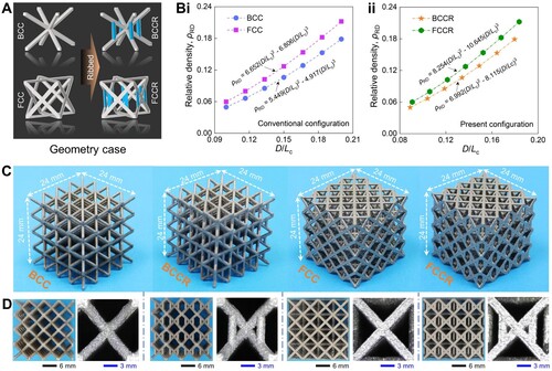
Figure 1. Design concept. (A) Increasingly complex geometric configurations including layered [Citation10], hybrid [Citation13], embedded [Citation16,Citation17], gradient [Citation18], bioinspired [Citation19] and hierarchical structures [Citation21]. (B) Illustration of bending and stretching in an inclined strut. (C) Improvements to node stresses [Citation27–29] and strut loads [Citation25,Citation30,Citation31]. (D) Concepts and significance of ribbed strategy for truss-lattice metamaterials.
![Figure 1. Design concept. (A) Increasingly complex geometric configurations including layered [Citation10], hybrid [Citation13], embedded [Citation16,Citation17], gradient [Citation18], bioinspired [Citation19] and hierarchical structures [Citation21]. (B) Illustration of bending and stretching in an inclined strut. (C) Improvements to node stresses [Citation27–29] and strut loads [Citation25,Citation30,Citation31]. (D) Concepts and significance of ribbed strategy for truss-lattice metamaterials.](/cms/asset/5de16fac-5cf2-4e67-b5f8-bc0200d826dc/nvpp_a_2337310_f0001_oc.jpg)
In the realm of metamaterials, nodes and struts stand out as two essential geometric components. The deformation modes of an inclined strut primarily fall into two categories: bending or stretching [Citation32]; [Citation33], as shown in (B). Structures dominated by bending exhibit a stable response history and lower energy absorption, while those dominated by stretching generally display fluctuating stress plateaus and higher energy absorption. Despite undergoing various geometric upgrades, the fundamental deformation mechanisms of strut-based metamaterials persist in being rooted in either bending- or stretching-dominated behaviour. In these mechanisms, nodes typically experience significant stress concentration, while struts guide the propagation of stress waves. Numerous efforts have been made to mitigate stress concentration [Citation27–29] and optimise load transfer [Citation25,Citation30,Citation31,Citation34,Citation35] in these systems, as shown in (C). As mentioned in the literature cited above, in recent years, upgrading strategies for lattice structures have been extensively investigated, achieving significant progress in various aspects. Therefore, building upon this foundation, pursuing strategies that are simpler, more efficient, and capable of surpassing the improvements brought by existing designs will face substantial challenges.
In this study, as proof of concept, we introduce a novel class of mechanical truss-lattice metamaterials based on body-centered cubic (BCC) and face-centered cubic (FCC) structures, denoted as BCCR and FCCR, respectively. These metamaterials incorporate rib reinforcements using a straightforward ribbed strategy, fostering a synergistic interaction between bending and stretching. This design approach effectively mitigates stress concentration at nodes while introducing multiple plastic hinges. As a result, the BCCR and FCCR structures demonstrate significant strength enhancements of 61.8% and 40.7%, respectively, compared to conventional BCC and FCC structures. Additionally, they exhibit improvements in energy absorption of 111% and 91%, respectively. The validation of these enhancements was achieved through a combination of experimental, numerical, and theoretical approaches. We believe that the presented strategy has the potential to inspire extensive future research aimed at exploring interpenetrating mechanisms and adapting them to various geometric configurations.
2. Materials and methods
2.1. Geometry and fabrication
The ribbed concept is validated using BCC and FCC geometries as the based structural carriers. The corresponding ribbed truss-lattice structures denoted as BCCR and FCCR, were designed following the strategy presented in (D). The ribs are placed along the loading direction since the struts experience significant bending and stretching deformation in that direction. Their geometric cases are illustrated in (A). In three-dimensional space, the nodes of the ribbed struts align with the midpoint of the original struts based on the simplest configuration and empirical methods. For the BCC, BCCR, FCC, and FCCR geometries, (Bi∼ii) illustrate the fitted mathematical relationships between the relative density and geometric parameters (diameter D and length Lc).
Figure 2. Geometric design and specimen demonstration. (A) Geometry case; (B) Relative density of (i) conventional structure and (ii) ribbed geometry; (D) Specimens fabricated with stainless-steel 316L; (E) Front view and enlarged unit cell diagrams of four samples.
The EOS M290 3D printing machine was utilised to additively manufacture the lattice specimens through the Direct Metal Laser Sintering (DMLS) technique with laser power of 400 W, spot diameter of 100 μm, layer thickness of 30 μm and layer speed of 2000mm/s. The commercial EOS stainless-steel 316L powder was chosen as the material for the printed matrix, whose composition is shown in . All the specimens shared the same geometric overall dimensions, measuring mm3 (as shown in (C)). Within this confined space,
unit cells were integrated in three orthogonal directions, satisfying the cell number sensitivity. This specific number of unit cell has been demonstrated to reliably achieve the convergence of mechanical properties. The strut diameters of conventional BCC and FCC structures are designed as 0.9 mm. To maintain the same relative density, the corresponding diameters of BCCR and FCCR truss-lattice structures are calculated as 0.804 and 0.822 mm via Computer Aided Design (CAD) software, respectively. The original and ribbed struts are controlled to have identical diameters after considering the appropriate overlapping effects. The geometrical information and specimen masses are presented in .
Table 1. Material composition of EOS stainless-steel 316L powder.
Table 2. Geometrical and mass information of experimental specimens (Lc = 24 mm).
2.2. Quasi-static compressions
To evaluate the mechanical behaviour of the specimens, quasi-static compression tests were performed. Compression tests were conducted at a controlled strain rate of 0.001 s−1 (equivalent to a compression speed of 1.44 mm/min) using the Shimadzu AG25-TB (50 kN), a high-precision and reliable testing machine. The selected strain rate ensures that the specimens are subjected to gradual and controlled deformation, enabling the precise observation and measurement of their response to compression forces. Four replicates of each lattice specimen were tested under the same experimental conditions. The energy absorption per unit volume () is defined as the area under compressive stress–strain curves [Citation36]. The specific energy absorption (SEA) can be defined as the ratio of the energy absorption per unit volume to the equivalent density (
) of the structure/material [Citation25]. Densification strain under compression is based on energy absorption efficiency [Citation25,Citation36–39] and determined by the strain corresponding to the last deflection point of the curve. Their expressions and related explanations are shown in .
Table 3. Evaluation indicators of mechanical properties.
2.3. Finite element analysis
Finite element analysis (FEA) is utilised to supplement experimental results and reveal mechanical mechanisms. All designed structures were modelled, meshed, and solved using SOLIDWORKS (Dassault Systèmes SolidWorks Corp.), HYPERMESH (Altair Engineering Inc.) and ABAQUS/CAE (Dassault Systèmes Simulia Corp.), respectively. Parametric modelling was implemented based on their respective scripting languages. Considering the experiment validation and computational efficiency, the approximate global mesh size was set to one-fourth of the strut diameter after performing the mesh convergence analysis (Section S1, Supplementary Material). The use of 4-node linear tetrahedral elements (C3D4) with a combination of small mesh size and large mesh count ensures computational solving accuracy. General contact (Explicit), surface pairs of all* with self, tangential behaviour of friction coefficient 0.2 and normal behaviour of hard contact were adopted to model the compression conditions. After conducting speed sensitivity analysis (Section S2, Supplementary Material), the loading speed of 1 m/s was set to achieve a balance between kinetic and internal energy, with a conservative threshold of 5%. The material behaviours of elastic-linear strain hardening were employed. The material data for stainless-steel 316L, obtained according to ISO 6892, includes a material density of 7.98 g/cm3, Young's modulus of 150 GPa, Yield strength of 460 MPa and ultimate tensile strength of 560 MPa. The strain rate and thermal softening were not introduced since the simulations were verifying experiments under quasi-static loading conditions. The ductile failure and damage evolution were not considered because no significant strut fractures were observed during the experimental compression process.
3. Results and discussion
3.1. Compressive behaviours
3.1.1. Mechanical response
shows the quasi-static compression results for all samples. The purpose of these tests is to elucidate how the structures respond under compressive loading conditions, with stress–strain curves serving as vital tools to characterise their mechanical behaviour. The results of the four compression tests for each structure are similar, as depicted in (Ai∼ii and Bi∼ii). The trends of the curves remain almost identical in both the elastic and plastic stages. This underscores the reliability of the fabricated samples and the repeatability of the experiments. Figure S3 shows the energy absorption efficiency curves for all compressed samples (Section S3, Supplementary Material).
Figure 3. The compression results from conventional and ribbed structures. (Ai∼iii) BCC v.s. BCCR; (Bi∼iii) FCC v.s. FCCR; (C) The comparison of energy absorption per unit volume and compression strength; (D) SEA comparison; (E) The increment in SEA value for different design strategies fabricated with metallic stainless-steel 316L, including embedded, variable cross-sections, hybrid, gradient, bio-inspired, and hierarchical metamaterials.
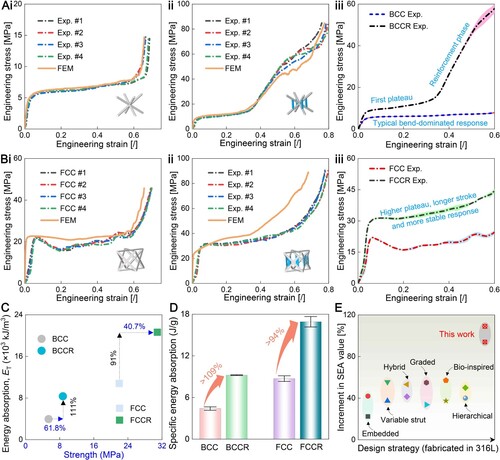
(Aiii) shows experimental comparisons of BCC and BCCR structures using error bands. The mechanical response of the BCC structure demonstrates a typical bending-dominated mode, and its stress–strain curve exhibits a flat tendency. In contrast, the BCCR structure with the same exhibits a different deformation response. Its compression behaviour presents two distinct steps: the pre-smooth process and the late enhancement stage. Before the strain reaches 33%, the BCCR structure undergoes a steady compressive deformation similar to that of the BCC structure, but its engineering stress is higher. However, there is a notable increase in stress for BCCR after the strain surpasses 33%, indicating an enhanced effect. Note that this increase in stress at this point does not imply that the BCCR structure has entered a densification stage. Energy absorption efficiency continues to increase in the interval between strain 33% and 70% (Figure S3B, Section S3, Supplementary Material). The mechanical characteristics of these structures suggest potential for application in passive safety protection devices and systems. These characteristics enable the structure to initially withstand a relatively gradual range of stresses when subjected to external load. Consequently, this enables the protected object to effectively shield against the initial impact loads. Subsequently, the structure transitions into an enhanced protection phase, achieving comprehensive resilience to deformation.
(Biii) presents the experimental comparison of the engineering stress–strain curves between FCC and FCCR structures. FCCR structures demonstrate superior mechanical performance, including higher plateau stress, extended strain-hardening phase, and more stable mechanical response. These findings distinctly highlight the substantial improvement in overall mechanical performance resulting from the implementation of ribbed strategies. Illustrated in (C), the energy absorption per unit volume for BCCR and FCCH structures increased by 211% and 191%, respectively, compared to BCC and FCC. (D) shows that BCCR and FCCH structures exhibit a SEA increase of at least 109% and 94%, respectively, compared to BCC and FCC. These performance improvements are attributed to adjustments in the overall mechanical response of the ribbed truss-lattice structures. Quantified compressive mechanical properties are listed in .
Table 4. Quantified compressive mechanical properties (Experiment).
Furthermore, we conducted a comparative analysis between increment in SEA value and design strategies, including embedded [Citation16,Citation40], variable cross-sections [Citation27,Citation41], hybrid [Citation13,Citation42], gradient [Citation11,Citation43], bio-inspired [Citation44,Citation45], and hierarchical architectures [Citation25,Citation46] as shown in (E). The increment in SEA value refers to the percentage increase in SEA values of the new structures compared to their corresponding original structures after implementing these strategies. These structures are fabricated by metal additive manufacturing using stainless-steel 316L. Their matrix structure type, detailed fabrication techniques and printing parameters are displayed in Table S1 (Section S4, Supplementary Material). The results indicate that the ribbed strategy enhances SEA to a greater extent compared to the other strategies. This strategy can be further extended to a variety of truss-lattice configurations, not limited to just BCC and FCC geometries. Additionally, this approach offers the benefit of simplified design and reduced additive manufacturing failure rates. This further emphasises its promising potential in the fields of materials engineering and structural design.
3.1.2. Deformation mode
The FEA results of BCC, BCCR, FCC, and FCCR truss-lattices are depicted in (A∼B). The FCC and FCCR structures may exhibit more defects in the final specimens due to the increased complexity of support requirements during metal additive manufacturing. As a result, the simulation results may be slightly higher than the experimental results. The deformation processes of these structures are illustrated in (A). Regarding stress response and deformation processes, there is a notable consistency between the numerical simulation results and experimental findings, confirming the reliability of FEA. There is a significant alteration in the stress distribution at the nodes of both BCC and FCC structures after ribbing. For the BCC structure, when the strain reaches 25%, the stresses are entirely concentrated at the nodes, resulting in a pronounced high-stress distribution in the node area. However, with the implementation of the novel strategy we proposed, the BCCR structure exhibits a significant improvement in stress distribution at the nodes under the same compressive strain, effectively transferring the high stresses. Similarly, the FCCR structure initially exhibits a widespread high-stress distribution before reinforcement. However, after the addition of ribs, stress redistributions result in reduced stress levels at the nodal regions and increased stress in the strut components. This phenomenon further emphasises the significant potential of the ribbed strategy in optimising and adjusting the mechanical performance of the structure.
Figure 4. Deformation process. (A) Comparison of compression results between quasi-static experiment and FEA simulation (ϵ = 25%); (B) Microscopic deformation distal from and proximal to the node ends via SEM.
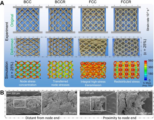
(B) presents a Scanning Electron Microscope (SEM) image capturing a strut from physical specimens. After the application of external loads, there is an increase in the number of microscopic cracks within the strut, and the sintered metal interfaces have started to fracture gradually. The degree of crack formation varies in different locations. At positions distant from the nodes, the occurrence of cracks is relatively limited and less conspicuous. However, in proximity to the nodes, extensive cracking becomes more prominent. This observation suggests that greater plastic deformation occurs in the nodes during the deformation process, resulting in the development of more pronounced cracks. Therefore, in the structural design of truss-lattice metamaterials, the node reinforcement holds significant importance.
3.2. Deformation mechanism
(Ai∼ii) illustrate the deformation sequences of representative volume unit cells for the four structures captured during both the experimental and simulation processes. At a compression strain of 25%, there is notable consistency in the key deformation locations between the experimental and simulation results. (B) presents simplified collapse sequence diagrams for both conventional and ribbed structures. In the case of the former, each node is connected to four struts. When subjected to an external load, these four struts undergo bending deformation relative to the centre node. As a result, stress is consistently transferred to the central node, resulting in stress concentration. This phenomenon is supported by the FEA contour plots in (A). The process of stress transfer essentially involves the dissipation of energy within the struts. As stress is fully transmitted to the nodes, the dissipated energy reaches the threshold of the structure. In the proposed configuration, the ribbed struts result in the emergence of new nodes along the original struts. Near these nodes, three additional struts are connected. The sections comprising the original struts still undergo bending deformation around the newly formed nodes. However, the introduction of an additional strut provides robust support to this node, effectively redistributing the stress borne by the new node back onto the struts. This augmentation creates a more intricate network of load-bearing elements, fundamentally altering the stress distribution dynamics within the structure. The ribbed structure involves a greater degree of deformation in the original struts, an increased number of nodes experiencing stress concentration, and a higher count of reinforcing struts providing support. This intricate interplay of elements characterises the enhanced structural configuration, showcasing a more intricate and distributed response to external loads. The enhancement not only amplifies the load-bearing capacity but also disperses stress more effectively, contributing to the overall resilience of the structure.
Figure 5. Deformation mechanism. (A) Extracted unit cell deformation processes of experimentation and simulation: (i) BCC v.s. BCCR; (ii) FCC v.s. FCCR. (B) Different collapse evolution between conventional and ribbed strategies. (C) Different distributions of (i) strut types correspond to (ii) different deformation patterns. (D) Theoretical and experimental comparison of mean plateau strength.
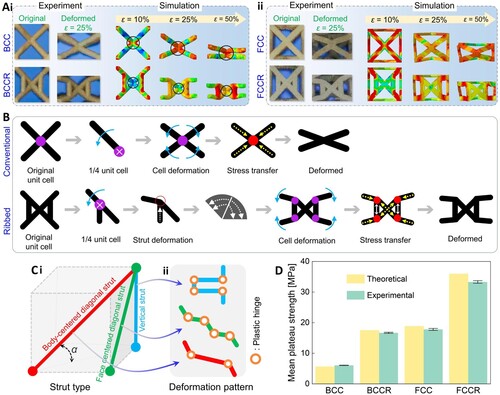
For strut-based metamaterial structures, the arrangement of struts in space can be divided into body-centered diagonal, face-centered diagonal, and vertical struts ((Ci)). They correspond to three different deformation modes and plastic hinge formation, as simplified in (Cii). Based on the energy absorbed by the strut [Citation38,Citation47], the mean plateau strength of plastic collapse was theoretically derived to supplement the validation of the mechanical mechanism, and it is calculated as:
(1)
(1)
The represents the angle between the diagonal and the base ((Ci)). The
denotes the length of the unit cell. The m, n, and p respectively represent the number of struts along the vertical, body-centered cubic diagonal, and face-centered cubic diagonal.
represents the tensile strength of matrix material. provides their corresponding values. The shared struts exist between adjacent unit cells in FCC and FCCR configurations. Consequently, the
of BCC, BCCR, FCC, and FCCR structures can be calculated using Equations (2∼5). Considering the actual diameters and lengths, the average plateau strengths are compiled in . A comparison with experimental values reveals a consistent alignment between the two, as illustrated in (D). Following the reinforcement design, the number of struts for the three types has changed, introducing more deformable plastic hinges. In comparison to the strut diameters, the energy dissipation in the plastic hinges takes precedence.
(2)
(2)
(3)
(3)
(4)
(4)
(5)
(5)
3.3. Further discussion
3.3.1. Length effect of ribbed strut
In the structures mentioned above, we positioned the rib at the midpoint of the strut. A new rib-node is introduced between the original two nodes of the original strut after ribbing ((A)). The varying position of the rib-node results in a change in the length of the ribbed strut. The ribbed length coefficient η is introduced, defined as the ratio of the ribbed strut's length to the unit cell's length. Two extreme values exist for η: when , the BCCR evolves into a BCC; when
, the BCCR transforms into a BCCZ, a structure reported in other literature [Citation37,Citation38]. The structures corresponding to
and
are different from the proposed BCCR configuration. To parametrically evaluate the effect of η value on mechanical enhancement, we set the strut diameter of BCC and FCC to be 0.6 mm. (A) also shows the schematic diagrams of geometric BCC-based and FCC-based unit cells. presents the corresponding strut diameters for the BCCR and FCCR structures, maintaining the same relative density. The compressive performance of these structures were analyzed using FEA methods with consistent solving setups and environments.
Figure 6. Comparison of mechanical properties for different ribbed strut lengths. (A) Schematic diagrams of geometric BCC-based and FCC-based unit cells; (B)∼(C) Engineering stress-strain curves; (D)∼(E) Energy absorption per unit volume; (F) The classification of mechanical characteristics for different structures.
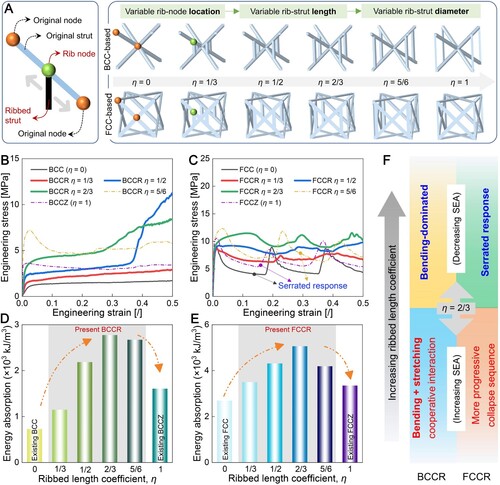
Table 5. Number of struts and mean plateau strength of different types in a unit cell.
Table 6. The diameter D of the ribbed strut with different η (unit: mm).
(B∼C) illustrates the stress–strain curves for varying ribbed strut lengths of BCCR and FCCR structures. Adjusting the length of the ribbed strut influences the stress evolution trend and mechanical response of the structure. This variation impacts the strength, stiffness, and overall performance of the structures under the same relative density. For BCCR, as η increases from 0 to 2/3, the developing strain of the strengthening phase is advanced corresponding to a decrease in slope. With further increases in η, the enhancement phase gradually disappears, and the curve trend approaches the traditional bending response. For FCCR, as η increases from 0 to 2/3, the serrated features in stretching deformation noticeably are improved, and a higher plateau with smaller fluctuations in mechanical response is experienced. As η continues to increase, this favourable state also diminishes, and the curve trend approaches the traditional fluctuating response observed in stretching deformation. (D∼E) illustrates the comparative analysis of energy absorption per unit volume for different geometric configurations. Under both matrix structures, similar trends are observed, characterised by an initial increase () followed by a decrease (
) in specific energy absorption. Based on this, (F) summarises the relationship between the reinforcement coefficient and mechanical characteristics, response mechanisms, and energy absorption. In the current design, a coefficient of 2/3 enables the truss-lattice structure to achieve optimal compression performance. This work can provide valuable insights for future structural geometric designs.
3.3.2. Damage tolerance behaviour
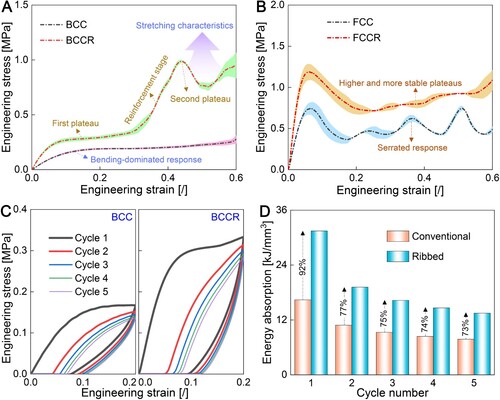
Damage tolerance refers to the permissible extent of initial defects and their progression during usage within a structure. The damage tolerance behaviour of ribbed truss-lattice metamaterial is demonstrated by evaluating energy absorption under cyclic compression [Citation48–50]. To evaluate the damage resistance characteristics of the proposed structure, resin-based samples were fabricated using the Voxelab Proxima 6.0 digital light processing (DLP) 3D printer (Zhejiang Flashforge 3D Technology Co., Ltd, China). The printing parameters include a layer height of 0.05 mm, base time of 3.5 s, and attach time of 35 s. Compression tests were performed on an Instron 5848 MicroTester with a load measurement precision of ±0.5%. The engineering stress–strain curves for a single quasi-static loading are depicted in (A∼B). The polymer truss-lattice structure exhibited a response trend similar to that of its metallic counterparts. After the reinforcement stage, the BCCR structure exhibited a distinct mechanical signature characterised by stretching dominance. The FCC structure exhibited a serrated response, however, the FCCR structure enhanced the plateau strength and improved the response fluctuations after ribbing. The performance enhancement of resin-ribbed polymer microlattice is analogous to that of metals, as both can be attributed to the disturbance of conventional collapse mechanisms by the presence of ribs. (C) provides details of stress curves after five cyclic loadings for both BCC and BCCR structures, each subjected to a compression strain of 20%. Despite a diminishing trend in energy absorption with an escalating number of cycles, the ribbed structure outperformed its conventional counterpart. Even after the fifth cycle loading, BCCR exhibited a 73% higher energy absorption with only a 15% loss in maximum strength than BCC, as illustrated in (D). Due to the formation of additional plastic hinges after ribbing, more compression energies are stored in the deformed struts of the BCCR structure under loading conditions. These energies are rapidly released after unloading. As a result, the ribbed structures consistently exhibit elevated strength and plateau characteristics after each cyclic loading.
Figure 7. Mechanical properties of structures fabricated with polymers. Engineering stress-strain curves of (A) BCC v.s. BCCR and (B) FCC v.s. FCCR structures under single compression. (C) Damage resistance behaviour of BCC and BCCR. (D) Energy absorption comparison under five cyclic loadings.
4. Conclusions
In conclusion, we have introduced a readily applicable structural design concept to enhance load-bearing capacity and energy absorption. The strategy involves customising the deformation mechanisms of conventional structures and introducing additional plastic hinges within the deformation sequence. The BCCR and FCCR truss-lattice structures fabricated using stainless-steel 316L were quasi-statically compressed. The results revealed a respective strength enhancement of 61.8% and 40.7% over conventional BCC and FCC, coupled with improvements in energy absorption of 111% and 91%, respectively. The deformation mechanisms involving combinations of bending and stretching interactions were consistently determined through experiments, simulations, and theoretical analyses. The length effects of the ribbed strut via FEA suggest that a reinforcement coefficient of 2/3 optimises compression performance for the ribbed truss-lattice. The damage-tolerant behaviour of resin-based ribbed structures was evaluated through cyclic compression loading, revealing that the BCCR structure still exhibited 73% higher energy absorption compared to BCC after the fifth cycle. The reduction of node stress concentrations, optimisation of load transfer paths, and integration of deformed plastic hinges cooperatively facilitate energy dissipation during the compression process. This study validates the rationale behind the ribbed strategy. However, the actual research extends beyond this, including the interaction effect between adjacent ribs, the hierarchical effects caused by more ribs and the matching effects of ribbed direction and position. The highlighted strategy transcends the limitations of these two basic truss-lattice structures, offering the potential for widespread applicability across various lattice geometries.
Supplemental Material
Download MS Word (630 KB)Acknowledgements
The authors would like to express their thanks.
Disclosure statement
No potential conflict of interest was reported by the author(s).
Data availability statement
The data that support the findings of this study are available from the corresponding author upon reasonable request.
Additional information
Funding
References
- Li X, Chua JW, Yu X, et al. 3D-printed lattice structures for sound absorption: current progress, mechanisms and models, structural-property relationships, and future outlook. Adv Sci. 2023: e2305232. doi:10.1002/advs.202305232.
- Li Z, Li X, Chua JW, et al. Architected lightweight, sound-absorbing, and mechanically efficient microlattice metamaterials by digital light processing 3D printing. Virtual Phys Prototyp. 2023;18(1):e2166851. doi:10.1080/17452759.2023.2166851.
- An Q, Li D, Liao W, et al. A novel ultra-wideband electromagnetic-wave-absorbing metastructure inspired by bionic gyroid structures. Adv Mater. 2023;35(26):e2300659. doi:10.1002/adma.202300659.
- Lee J, Lim DD, Park J, et al. Multifunctionality of additively manufactured Kelvin foam for electromagnetic wave absorption and load bearing. Small. 2023: e2305005. doi:10.1002/smll.202305005.
- Zou B, Liang Z, Zhong D, et al. Magneto-thermomechanically reprogrammable mechanical metamaterials. Adv Mater. 2023;35(8):e2207349. doi:10.1002/adma.202207349.
- Mueller J, Lewis JA, Bertoldi K. Architected multimaterial lattices with thermally programmable mechanical response. Adv Funct Mater. 2021;32(1):202105128. doi:10.1002/adfm.202105128.
- Isaac CW, Duddeck F. Current trends in additively manufactured (3D printed) energy absorbing structures for crashworthiness application – a review. Virtual Phys Prototyp. 2022;17(4):1058–1101. doi:10.1080/17452759.2022.2074698.
- Isaac CW, Duddeck F. Recent progress in 4D printed energy-absorbing metamaterials and structures. Virtual Phys Prototyp. 2023;18(1):e2197436. doi:10.1080/17452759.2023.2197436.
- Isaac CW, Sokołowski A, Duddeck F, et al. Mechanical characterisation and crashworthiness performance of additively manufactured polymer-based honeycomb structures under in-plane quasi-static loading. Virtual Phys Prototyp. 2023;18(1):e2273296. doi:10.1080/17452759.2023.2273296.
- Traxel KD, Groden C, Valladares J, et al. Mechanical properties of additively manufactured variable lattice structures of Ti6Al4 V. Mater Sci Eng A-Struct. 2021;809:140925. doi:10.1016/j.msea.2021.140925.
- Rodrigo C, Xu S, Durandet Y, et al. Mechanical response of functionally graded lattices with different density grading strategies. Thin-Walled Struct. 2023;192:111132. doi:10.1016/j.tws.2023.111132.
- Wang X, Qin R, Zhang X, et al. Quasi-static and dynamic behavior of additively manufactured metamaterial structures with layered-hybrid topologies. Thin-Walled Struct. 2023;183:110434. doi:10.1016/j.tws.2022.110434.
- Xiao L, Xu X, Feng G, et al. Compressive performance and energy absorption of additively manufactured metallic hybrid lattice structures. Int J Mech Sci. 2022;219:107093.
- Zhang J, Huang H, Liu G, et al. Stiffness and energy absorption of additive manufactured hybrid lattice structures. Virtual Phys Prototyp. 2021;16(4):428–443. doi:10.1080/17452759.2021.1954405.
- Li D, Qin R, Xu J, et al. Topology optimization of thin-walled tubes filled with lattice structures. Int J Mech Sci. 2022;227:107457. doi:10.1016/j.ijmecsci.2022.107457.
- Wang Z, Zhou Y, Wang X, et al. Compression behavior of strut-reinforced hierarchical lattice—Experiment and simulation. Int J Mech Sci. 2021;210:106749. doi:10.1016/j.ijmecsci.2021.106749.
- Wang X, Li Z, Li X, et al. Customizable plateau in face-centered cubic hierarchical lattices achieved by self-similar embedded design. Mater Des. 2023;233:112186. doi:10.1016/j.matdes.2023.112186.
- Bai L, Gong C, Chen X, et al. Mechanical properties and energy absorption capabilities of functionally graded lattice structures: experiments and simulations. Int J Mech Sci. 2020;182:105735. doi:10.1016/j.ijmecsci.2020.105735.
- Wu H, Chen J, Duan K, et al. Three dimensional printing of bioinspired crossed-lamellar metamaterials with superior toughness for syntactic foam substitution. ACS Appl Mater Interfaces. 2022;14(37):42504–42512. doi:10.1021/acsami.2c12297.
- Guo X, Li X, Wang E, et al. Bioinspired hierarchical diamond triply periodic minimal surface lattices with high energy absorption and damage tolerance. Addit Manuf. 2023;76; doi:10.1016/j.addma.2023.103792.
- Wang Y, Xu F, Gao H, et al. Elastically isotropic truss-plate-hybrid hierarchical microlattices with enhanced modulus and strength. Small. 2023;19(18):e2206024. doi:10.1002/smll.202206024.
- Bian Y, Wang R, Yang F, et al. Mechanical properties of internally hierarchical multiphase lattices inspired by precipitation strengthening mechanisms. ACS Appl Mater Interfaces. 2023;15(12):15928–15937. doi:10.1021/acsami.2c20063.
- Wang X, Qin R, Chen B, et al. Multi-scale collaborative optimization of lattice structures using laser additive manufacturing. Int J Mech Sci. 2022;222:107257. doi:10.1016/j.ijmecsci.2022.107257.
- Wang X, Qin R, Lu J, et al. Laser additive manufacturing of hierarchical multifunctional chiral metamaterial with distinguished damage-resistance and low-frequency broadband sound-absorption capabilities. Mater Des. 2024;238:112659. doi:10.1016/j.matdes.2024.112659.
- Wang P, Yang F, Zheng B, et al. Breaking the tradeoffs between different mechanical properties in bioinspired hierarchical lattice metamaterials. Adv Funct Mater. 2023: 2305978. doi:10.1002/adfm.202305978.
- Zeng Q, Duan S, Zhao Z, et al. Inverse design of energy-absorbing metamaterials by topology optimization. Adv Sci. 2023;10(4):e2204977. doi:10.1002/advs.202204977.
- Cao X, Duan S, Liang J, et al. Mechanical properties of an improved 3D-printed rhombic dodecahedron stainless steel lattice structure of variable cross section. Int J Mech Sci. 2018;145:53–63. doi:10.1016/j.ijmecsci.2018.07.006.
- Dong L, Zhang S, Yu K. Ti–6Al–4V truss lattices with a composite topology of double-simple-cubic and body-centered-cubic. Eur J Mech A Solids. 2022;92:104486; doi:10.1016/j.euromechsol.2021.104486.
- Wei Y-L, Yang Q-S, Liu X, et al. Multi-bionic mechanical metamaterials: a composite of FCC lattice and bone structures. Int J Mech Sci. 2022;213:106857. doi:10.1016/j.ijmecsci.2021.106857.
- Alomar Z, Concli F. Compressive behavior assessment of a newly developed circular cell-based lattice structure. Mater Des. 2021;205:109716. doi:10.1016/j.matdes.2021.109716.
- Liu C, Lertthanasarn J, Pham MS. The origin of the boundary strengthening in polycrystal-inspired architected materials. Nat Commun. 2021;12(1):4600. doi:10.1038/s41467-021-24886-z.
- Zhong H, Das R, Gu J, et al. Low-density, high-strength metal mechanical metamaterials beyond the Gibson-Ashby model. Mater Today. 2023;68:96–107. doi:10.1016/j.mattod.2023.07.018.
- Zhong H, Song T, Li C, et al. The Gibson-Ashby model for additively manufactured metal lattice materials: its theoretical basis, limitations and new insights from remedies. Curr Opin Solid State Mater Sci. 2023;27(3). doi:10.1016/j.cossms.2023.101081
- Zhang Y, Aiyiti W, Du S, et al. Design and mechanical behaviours of a novel tantalum lattice structure fabricated by SLM. Virtual Phys Prototyp. 2023;18(1):e2192702. doi:10.1080/17452759.2023.2192702.
- Chua C, Leong Sing S, Chua CK. Characterisation of in-situ alloyed titanium-tantalum lattice structures by laser powder bed fusion using finite element analysis. Virtual Phys Prototyp. 2022;18(1):e2138463. doi:10.1080/17452759.2022.2138463.
- Wang X, Li X, Li Z, et al. Superior strength, toughness, and damage-tolerance observed in microlattices of aperiodic unit cells. Small. 2024: 2307369. doi:10.1002/smll.202307369.
- Liu H, Gu D, Qi J, et al. Dimensional effect and mechanical performance of node-strengthened hybrid lattice structure fabricated by laser powder bed fusion. Virtual Phys Prototyp. 2023;18(1):e2240306. doi:10.1080/17452759.2023.2240306.
- Ye J, Sun Z, Ding Y, et al. The deformation mechanism, energy absorption behavior and optimal design of vertical-reinforced lattices. Thin-Walled Struct. 2023;190:110988. doi:10.1016/j.tws.2023.110988.
- Zhang X, Jiang L, Yan X, et al. Revealing the apparent and local mechanical properties of heterogeneous lattice: a multi-scale study of functionally graded scaffold. Virtual Phys Prototyp. 2022;18(1):e2120406. doi:10.1080/17452759.2022.2120406.
- Li L, Yang F, Li P, et al. A novel hybrid lattice design of nested cell topology with enhanced energy absorption capability. Aerosp Sci Technol. 2022;128:107776. doi:10.1016/j.tws.2022.110439.
- Wang Z, Cao X, Yang H, et al. Additively-manufactured 3D truss-lattice materials for enhanced mechanical performance and tunable anisotropy: simulations & experiments. Thin-Walled Struct. 2023;183:110439. doi:10.1016/j.tws.2022.110439.
- Wu J, Zhang Y, Yang F, et al. A hybrid architectural metamaterial combing plate lattice and hollow-truss lattice with advanced mechanical performances. Addit Man. 2023;76:103764. doi:10.1016/j.addma.2023.103764.
- Zhang J, Xie S, Li T, et al. A study of multi-stage energy absorption characteristics of hybrid sheet TPMS lattices. Thin-Walled Struct. 2023;190:110989. doi:10.1016/j.tws.2023.110989.
- Wang P, Yang F, Li P, et al. Bio-inspired vertex modified lattice with enhanced mechanical properties. Int J Mech Sci. 2023;244:108081. doi:10.1016/j.ijmecsci.2022.108081.
- Wang P, Yang F, Lu G, et al. Anisotropic compression behaviors of bio-inspired modified body-centered cubic lattices validated by additive manufacturing. Compos Part B: Eng. 2022;234:109724. doi:10.1016/j.compositesb.2022.109724.
- Wang P, Yang F, Ru D, et al. Additive-manufactured hierarchical multi-circular lattice structures for energy absorption application. Mater Des. 2021;210:110116. doi:10.1016/j.matdes.2021.110116.
- Zhang H, Zhou H, Zhou Z, et al. Energy absorption diagram characteristic of metallic self-supporting 3D lattices fabricated by additive manufacturing and design method of energy absorption structure. Int J Solids Struct. 2021;226–227:111082. doi:10.1016/j.ijsolstr.2021.111082.
- Li Z, Li X, Wang X, et al. Interpenetrating hollow microlattice metamaterial enables efficient sound-absorptive and deformation-recoverable capabilities. ACS Appl Mater Interfaces. 2023;15(20):24868–24879. doi:10.1021/acsami.3c02498.
- Li Z, Li X, Wang Z, et al. Multifunctional sound-absorbing and mechanical metamaterials via a decoupled mechanism design approach. Mater Horiz. 2023;10(1):75–87. doi:10.1039/D2MH00977C.
- Li Z, Wang X, Li X, et al. New Class of Multifunctional Bioinspired Microlattice with Excellent Sound Absorption, Damage Tolerance, and High Specific Strength. ACS Appl Mater Interfaces. 2023;15(7):9940–9952. doi:10.1021/acsami.2c19456.