
 ?Mathematical formulae have been encoded as MathML and are displayed in this HTML version using MathJax in order to improve their display. Uncheck the box to turn MathJax off. This feature requires Javascript. Click on a formula to zoom.
ABSTRACT
Metamaterials possess properties not found in nature and are expected to revolutionise the design of structural components. However large-scale production of metallic metamaterials remains locked due to the compromise between print size and resolution in existing metal 3D printing methods. We unlock the possibility of 3D printing of stainless steel metamaterials across scales using lithography metal manufacturing, a vat photopolymerisation technology that uses digital light processing (DLP) on metal-filled resin to 3D print a green body for further debinding and sintering in a furnace. Here in, were explore the effects of energy dose on overpolymerisation, minimal feature size, and print resolution as well as the effects of sintering temperature on microstructure, shape stability, and mechanical properties of 3D printed metamaterials. It has become possible to 3D print steel metamaterials with a twist and auxetic metamaterials with micro-scaled structures on a decimetre scale. Our benchmarking experiments demonstrate that lithography metal manufacturing competes with laser powder bed fusion regarding print accuracy, surface roughness, and design freedom and provides a viable solution for translating metallic metamaterials from laboratories to markets.
1. Introduction
A paradigm shift in material design is expected due to the maturity of metamaterials [Citation1]. Metamaterials exhibit properties beyond those usually found in nature, owing to their engineered shapes and compositions [Citation2]. They emerged two decades ago and today address nearly all conceivable aspects of solids, from mechanical, acoustic, electromagnetic, and optical to transport properties [Citation2]. Metamaterials typically consist of microstructured three-dimensional (3D) periodic lattices, especially mechanical metamaterials, whose properties are determined solely by their geometry and integral material properties [Citation3]. The preferred materials for most engineering applications are metals and alloys. However, manufacturing metallic microlattices on a macroscale is difficult. Therefore, despite the current research boom, most metamaterials remain proof of concept on millimetre-sized samples [Citation2].
The existing fabrication processes of microstructured metallic metamaterials are complex and often not commercially viable [Citation4]. Thus, most metamaterials were made either in theory or in polymers [Citation5–7]. One process of making metallic metamaterials first prints a polymeric mould, then deposits metal inside via either microcasting or electroforming, and finally removes the polymeric mould through chemical etching [Citation8,Citation9]. In a derivative approach, dip-coating, laser ablation, and chemical etching were sequentially applied to fabricate microstructures in metal [Citation10]. Another method to fabricate large microstructured parts is to design them with connectors that can be used to assemble the building blocks after printing [Citation4]. Unfortunately, such procedures are complex and require an extensive range of equipment and in-house expertise in many high-end fabrication technologies. In other words, no methods are currently commercially viable for producing decimetre devices with micro-features, such as metamaterials. Multiscale metal manufacturing technology is required to bring metamaterials from labs to markets [Citation4].
Additive manufacturing (AM) processes have been undergoing intensive development over the last 30 years [Citation11] and were the main tool for experimental proving of metamaterials [Citation3]. Despite new AM systems being commercialised, most are limited to fabricating either high-accuracy small parts or low-accuracy middle-size parts [Citation12]. Accurate metal AM techniques, such as electron beam melting, binder jet (BJ) printing, and two-photon lithography, rely on a single energy source to print voxel-by-voxel and thus have low productivity and size limitations [Citation13]. Productive AM processes, such as directed energy deposition [Citation14–16] and extrusion-based metal printing [Citation17–21], lack the accuracy and resolution to produce fine structures. Other AM methods (e.g. selective laser melting (SLM)) provide decent print accuracy, yet require support structures that drastically limit the design freedom or compromise the part’s performance. In general, all AM processes are based on the trade-off between three technological aspects: maximum part size, printing accuracy, and productivity [Citation22]. A metal AM process combining high productivity, micro-accuracy, and a decimetre part size could enable the on-demand production of metamaterials [Citation3].
Lithography metal AM (LMAM) is an emerging concept that can potentially print large parts at a high resolution and production speed [Citation23]. The LMAM method is based on vat photopolymerisation principles of metal-filled photosensitive polymeric resin via digital light processing (DLP), which projects a 2D image polymerising a complete layer in a matter of seconds instead of voxel-by-voxel printing using a laser. Although DLP has been extensively studied for printing ceramic parts [Citation24], only two attempts have been reported to print in metals. In 2020, Nguyen et al. [Citation25] assembled a DLP setup for printing with metal and revealed that steel powder segregates from resin and is difficult to cure compared to ceramic-filled resin. In 2021, Roumanie et al. [Citation26] printed copper parts and revealed an oxidation issue during the sintering process. Both studies [Citation25,Citation26] demonstrated only a few bulk parts in the form of a cylinder or a gear without microstructures. At the same time, these previous studies [Citation25,Citation26] evidenced that lithographic printing with metal differs from that with ceramics due to differences in density, reflectivity, thermal behaviour, chemical reactivity, and other properties. Therefore, the knowledge accumulated for lithographic printing in ceramics is not directly transferable to printing with metals. We recently presented an LMAM setup and process to print metallic parts with a minimal feature size of 100 µm [Citation23]. However, many scale-up issues emerged when we tried to print a decimetre-sized part with structures sized at 100 µm. We sought solutions in the literature and industry and realised that the challenges of multiscale metal 3D printing we faced had not been reported. The lack of knowledge on multiscale LMAM forms a technological gap, which is largely filled in this study.
This study evolves LMAM technology for producing microstructured metallic metamaterials on the decimetre scale (9 × 5.5 × 12 cm). The technological challenges and proposed solutions for multiscale LMAM are presented for the first time. We demonstrate how to overcome the geometrical overgrowth between microstructures, feedstock segregation, microstructure decaking, insufficient strength of green microstructures in a macroscale assembly, surface oxidation, carbonisation, and the effect of sintering temperature on the shape and performance of metamaterials. Thus, various microstructured metamaterials recently reported in the Science and Nature magazines were printed on a centimetre scale in metal and mechanically tested with a digital image correlation setup. The benchmarking experiments revealed that LMAM competes with powder bed systems regarding print accuracy, roughness, and design freedom and provides a viable solution for translating metallic metamaterials from laboratories to markets.
2. Materials and methods
2.1. Printing setup
The LMAM process was realised on a newly developed DLP printer for metal-filled resins (Hammer Lab35, Incus GmbH, Vienna, Austria). We recently presented its operational principles in Ref. [Citation23]. This section elaborates on the process aspects critical for multiscale printing.
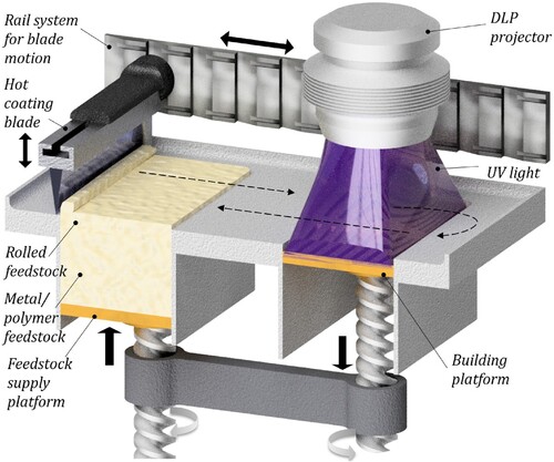
Metals are typically several times denser than ceramics, and thus metal-filled resins are dense, unlike viscous ceramic-filled resins. Thus, ceramic DLP printers (e.g. CeraFab by Lithoz) with a bottom-up approach do not suit the purpose. Printing with metals requires a top-down setup, as illustrated in . The setup was designed to take advantage of two phenomenological properties of the feedstock: UV light sensitivity and phase transition at low temperatures. At room temperature, our metal-filled polymeric feedstock is in the solid phase, but it becomes liquid when heated above 50°C. To employ the phase transition phenomenon, the process incorporates several steps. The hot blade touches the table and moves horizontally above the solid feedstock scrapping a thin layer of feedstock in front of it. Due to the thermal effect of the hot blade, the feedstock melts and gets rolled by the hot blade from the supply platform to the build platform (1). The build platform is coated with a feedstock layer, which is then cured using the DLP projector (wavelength <390 nm) installed above according to the 2D computer-aided design (CAD) pattern (2). Further, the build platform moves down for a determined layer thickness (3), whereas the supply platform moves up to allow new feedstock to be rolled again (4). The process repeats until the part reaches its designed height. An additional and distinctive feature of this setup is controlling the feedstock temperature in three locations: on the coating blade, build platform, and chamber. This solves the problems of powder segregation, lack of support, and feedstock reuse, as explained in Section 3.3.
Figure 1. Scheme of the lithography metal additive manufacturing process.
2.2. Metal-filled polymer feedstock
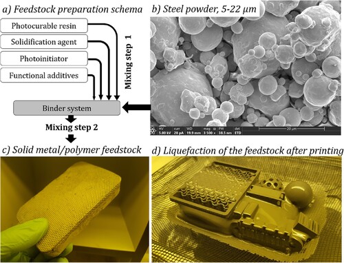
The feedstock preparation components, preparation procedure, and phase transition are depicted in . The feedstock consists of two main components: an organic binder system and metallic powder. The binder system is a mix consisting of 30% to 60% for photocurable resins (acrylates, methacrylates, and thioethers); 30% to 60% for the thermal solidification agent (wax type), reducing the overall viscosity of the binder at room temperature; 2% to 5% for the photoinitiator, triggering the polymerisation via ultraviolet (UV) light; and 1% to 3% for functional additives, including dispersing agents and light absorbers, to facilitate decaking and reduce overpolymerisation, respectively. The second component of the feedstock was 316L stainless steel powder with a size of 5–22 µm supplied by Sandvik-Osprey Ltd, UK. The metallic content in the feedstock was 55% by volume and 88% by weight. The powder and binder were dispersed in a Speedmixer (Hauschild, Hamm, Germany) dual-centrifugal mixing device to achieve a homogeneous metal–polymer feedstock. The exact binder composition is proprietary and for the purpose of reproducibility the results presented here can be ordered from Incus GmbH as binder system BMP18.
Figure 2. Photosensitive metal/polymer feedstock for the lithography metal additive manufacturing process.
2.3. Printing parameters, debinding and sintering
The LMAM process consists of three major steps: polymerising a green part (1), decaking/cleaning (2), and debinding and sintering (3). The generic procedure is given briefly below, while more details are provided in the related sections.
The exposure parameters, such as the energy intensity (100 mW/cm2) and exposure time (2–10 s), were adjusted to study the effect of the energy dose on the cure depth and overpolymerisation in the range from 200 to 1000 mJ/cm2 (discussed in Section 3.1). The layer thickness was fixed to 25 µm, as demonstrated in Section 3.2. The total time for accomplishing one layer was 50–60 s.
In the decaking step, the polymerised body (green part) was separated from the uncured feedstock by heating the overall volume to 45°C to melt the wax component and liquefy the uncured binder to drain, leaving the green parts to stand alone (see (d)). Finally, a solvent-based solution was sprayed over the fine structures to dissolve the undrained resin residuals, as explained in Section 3.4.
The organic component was thermally degraded in the debinding step, and the metal powder melted into a solid part in the sintering step. The previous differential scanning calorimetry and thermogravimetric analysis suggested these steps should be at 450°C and 1350°C, respectively [Citation23]. In this experiment, the green parts were debinded and presintered in a tube furnace using a 14-h thermal programme with several ramps and plateaus (Figure S2). The temperature was kept at 350°C, 450°C and 600°C for 150, 60 and 30 min, respectively, to pyrolyse of the organic binder before pre-sinter at 900°C for 60 min. The heat treatment was performed under a continuous flow of nitrogen (100 cm3/min) and hydrogen (20 cm3/min) maintained at a 10-torr vacuum. Further details of the sintering process are discussed in Sections 3.7–3.9.
2.4. Mechanical testing and characterisation
The assessment of the geometrical accuracy of the 3D printed parts was conducted using scanning electron microscopy FEI Quanta3D FEG SEM/FIB (FEI, Oregon, USA). The microscope was equipped with field emission gan for energy dispersive spectroscopy. The samples were cut into small pieces, fixed on the sample holder, sputtered with 5 nm thick Iridium coating to prevent charging of organic content, and scanned at different angles (10–60°) as it was done in Ref. [Citation27]. The 3D-printed surface topography and surface roughness were evaluated using the NV7300 Zygo Optical Profiler (Zygo, Middlefield, USA). The optical data was used to quantify the actual dimensions of the 3D printed features and calculate of the mean average and maximum height of the rough surface (surface roughness parameters Sa and Sz) following ISO 25178-2 as explained in Ref. [Citation28].
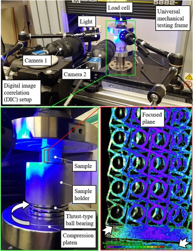
The mechanical properties of the printed metamaterials were evaluated by using an in-house developed assembly including a universal testing machine Instron 5882 synchronised with a stereo digital image correlation (stereo-DIC) setup and a customised rotational sample stage as shown in . Specifically, the optical system consisted of Sony IMX253 cameras and Nikkor 50 mm 1.8 D lenses, while Tokina 100 mm F2.8 atx-i lenses were used for the smaller samples. For the auxetic metamaterials, the samples were placed over a rigid plate and the deformation of the samples was captured using high resolution camera. The longitudinal and transverse deformations were measured by tracking the displacements of four points at the middle of the samples using Matlab. The longitudinal () and transverse strains (
) were calculated based on the measured displacements and the Poisson’s ratio was calculated as
. The Poisson’s ratio was computed based on the elastic strains only (elastic region of the force–displacement curve). For the twist metamaterials, the samples were supported by the rotational stage, where a ball bearing was used to allow the rotation of the lower boundaries of the sample, while it was pressed from the upper boundaries. The in-plane rotation of the cells and the global out-of-plane rotation were measured using DIC. The in-plane rotation around the local surface normal was directly obtained from VIC-3D. However, this twist material should also create out-of-plane rotation, and Python was used to extract this information. The coordinates of a flat domain are exported, and a singular value decomposition is performed to determine the surface's normal orientation. The orientation of this rotation is subsequently used to verify that the rotation occurs around the correct axis, while the magnitude is used to obtain the angle.
Figure 3. Mechanical testing setup with digital image correlation.
3. Results on printing and postprocessing
3.1. Effect of energy dose on overpolymerisation
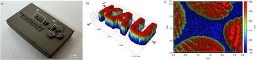
Overpolymerisation is related to the light scattering phenomenon and results in the geometrical overgrowth of the exposed volume [Citation24]. Thus, the cured geometry is larger than that in the CAD file when printing with ceramic-filled resins [Citation29]. Herein, we demonstrate that overpolymerisation is also an issue for printing with metal-filled resin and integrate an offset method to compensate it. demonstrates the effect of overpolymerisation on the accuracy of printed microstructures. We printed a 10 × 15 mm block with the title and logo of the university placed above the surface ((a)). The larger font of the text (2 mm high) allowed the distinct appearance of the university title ((b)). However, overpolymerisation resulted in blocking the 1-mm-deep and 200-µm-wide microchannels on the university logo, failing to reveal the intended design ((c)). Previous studies with ceramic-filled resins have concluded that the extent of overpolymerisation is proportional to the curing energy dose [Citation29]. However, no such studies were reported for printing with metal-filled resins. Analysing the effect of energy dose on overpolymerisation in LMAM may enable higher printing resolution.
Figure 4. Effect of overpolymerisation on geometrical accuracy in microstructures.
To analyse the effect of energy dose on lateral overpolymerisation, three arrays of 70-µm-wide rectangles with gaps of 35, 70, 105, and 140 µm between them were polymerised using three energy doses: 200, 500, and 1000 mJ/cm2, respectively. The solidified geometries are illustrated in (a). The width of all rectangles was 125 ± 10 µm, instead of the designed 70 µm, indicating 55 ± 10 µm overgrowth independent of the energy dose. The first two gaps, 35 and 70 µm, were insufficient to separate the features. The standalone rectangles appeared only when the gap was >105 µm. In -I–III, the decrease in energy dose of five times (from 1000 to 200 mJ/cm2) reduces the overgrowth only marginally. Quantitative evaluation of the effect of cure energy dose on the lateral overpolymerisation using light interferometry is shown in . At the highest energy dose, the overgrown was only 20 µm, which is up to 10 times less than the overgrowth of ceramic (zirconia) structures [Citation29]. Mitteramskogler et al. [Citation29] claimed that the light scattering within the ceramic-filled slurry and consequent overgrowth is sensitive to both exposure area and energy dose. For the 2 cm large features, the overgrowth increased from 100 to 400 µm when doubling the curing energy dose. In their experiment, the overpolymerisation was particularly expressed for the degassed slurry impaling on the role of oxygen inhibition. However, in the case of metal-filled resin, the proportionality of the geometrical overgrowth to the curing energy is much weaker than in ceramic resin. In addition, the dependency of cure depth on energy dose in polymeric resin is often linear [Citation30], and a logarithmic for ceramic resin [Citation29], yet it is nearly step function for metallic resin (this study), where the saturation happens abruptly at the depth of about 2–3 diameters of the filling particles. This can be attributed to the fact that the size of ceramic powder is typically within one micron, while metallic powder here is for one order of magnitude larger (5–22 µm). Using smaller powders for metal printing is commercially unjustified. Overall, overpolymerisation reduces the printing accuracy for almost two pixels, and a significant reduction of the curing energy dose cannot compensate for it.
Figure 5. Effect of energy dose on overpolymerisation in lithography metal manufacturing.
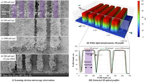
To overcome overpolymerisation, a contour offset was introduced by programming the digital micromirror device to shift the inner and outer contours of the exposure 2D pattern for a custom value. The double-sided overgrowth was 55 µm; thus, the custom value for the offset was set to −25 µm from the inner and outer contours. As a result, the solidified features were printed with the exact dimensions of those in the CAD file ((a)-I). Thus, the effect of overpolymerisation can be compensated using the digital offset ensuring that the dimensions of the printed part correspond to its CAD model. In conclusion, the lateral overgrowth in metal-filled resin is constant and nearly independent of the energy dose and thus can be compensated via the digital offset.
3.2. Defining the minimal feature size and resolution
The printing resolution in AM is intuitively associated with the pixel size and layer thickness; however, such a resolution is often unachievable in practice [Citation13,Citation31]. In fact, the minimal feature size by the existing metal AM methods, such as powder bed fusion (PBF), is far larger than the layer thickness [Citation32]. For instance, the layer thickness in powder bed fusion (PBF) typically ranges within 25–70 µm, while the smallest feature possible to print is 250–500 µm, depending on the shape and orientation of the feature [Citation33,Citation34]. The layer thickness in LMAM is also 25 µm, however actual print resolution and minimal feature size have not been reported.
To study the actual print resolution and the smallest printable features, an array of 100-µm tall rectangles with thickness of 1, 2, and 4 layers was designed, which corresponded to 25, 50, and 100 µm. shows the effect of number of layers on the actual thickness of the printed rectangles. All rectangles were printed with only a marginal difference in thickness compared to their intended design. Remarkably, even the rectangles with single-layer thickness were able to stand alone above the surface with an actual thickness of nearly 30 µm (instead of the designed 25-µm). It proves that the resolution of the printed part can be precisely controlled down to the thickness of a single layer. Moreover, the marginal overgrowth of only 5 µm allows precise dimensional clearances between the features. Overall, the actual print resolution in LMAM corresponds to the layer thickness.
Figure 6. Printing resolution and minimum feature size using lithography metal additive manufacturing.
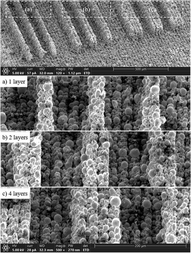
These results imply that polymerisation in metal-filled resin is different from that in other resins. In lithographic printing with pure polymeric resin or ceramic-filled resin, each layer solidifies thicker than designed because the actual cure depth is thicker than a single layer of resin due to the deep light penetration [Citation35]. Thus, curing of one layer also cures the uncured volume in the previous layer. This undesired curing thickens the freestanding features and distorts the geometry of hanging structures. When printing in resin and ceramic-filled resin, the cure depth undergoes a slight logarithmic dependency on the energy dose [Citation36–38]. However, when printing with metal-filled polymer the solidification ends at a certain distance sharply independently of the curing energy dose [Citation23]. This finding is because the metallic powders (5–22 µm) are significantly larger than the typically used ceramic powders [Citation29], and their high loading in the binder (55% wt) more strongly obstructs light penetration inside the binder. Therefore, the layer thickness is independent of the energy dose and the micro-features consisting of a single layer can be printed.
3.3. Overcoming metal–polymer segregation
Feedstock segregation is the phenomenon in which the metallic powder settles on the bottom of the platform, whereas polymer resin rises owing to the significant difference in density. The segregation results in two issues: (a) compromised support for the overhanging microstructures and (b) low metal content in the feedstock, jeopardising the integrity of the part. To overcome these issues, Nguyen et al. [Citation25] offered a two-step exposure strategy. The whole print area was first exposed to a low-energy dosage to solidify the suspension slightly. Then, a designed layer geometry was exposed beyond the activation energy to polymerise the suspension fully. The strategy [Citation25] addressed issues (a) and (b) at the cost of creating two new issues. The ‘pre-exposed’ suspension (c) complicates the decaking of the green body and (d) renders it not reusable. Partially polymerised resin has a high viscosity and surface tension, which complicates or fully disables the possibility of decaking parts with microstructures. Furthermore, pre-exposure limits the reuse of the suspension due to the accumulative activation of the photosensitive component. Even if the build volume is fully stuffed with CAD models, the volume of uncured feedstock can reach 80%, depending on the part complexity. Thus, feedstock reuse is a critical aspect of LMAM sustainability, currently compromised by the pre-exposure strategy. Alternative approaches to prevent filler–resin segregation are needed.
To overcome metal powder segregation without compromising other process aspects, the consolidation of the uncured regions in the developed process is controlled by the dual temperature system. The printing system was enclosed in the cooling chamber maintained at 18°C. Since the viscosity of the UV curable suspensions inversely depends on temperature [Citation24], lower temperature ensures higher viscosity of the used binder system. The addition of wax amplified this dependency, making the suspension brittle at 18°C and flowing at 45°C. The heating element was embedded inside the recoating blade and maintained at 80°C to liquefy the suspension during layer recoating. The rheological behaviour of the used feedstock has been studied in detail in Ref. [Citation23] showing that the viscosity decreases to <20 at a shear rate of 50 s−1. Differentiating the recoating blade temperature from that of the build platform allowed uniform recoating of the liquid suspension over the print bed and its rapid solidification, preventing metal–polymer segregation. In this way, all four requirements to uncured feedstock were achieved: (a) no metal–polymer segregation, (b) a support function for overhanding structures, (c) good liquefaction for decaking, and (d) possibility of feedstock reuse.
To demonstrate the validity of the proposed strategy, we fabricated an array of two spinning helixes with 200-µm-wide profiles spinning spirally around each other at a distance of 200 µm between them (). The structures were inspired by the photonic metamaterial by Gansel et al. [Citation8], who used a multistep fabrication procedure (stereolithography, electroforming, wet etching, etc.) to fabricate similar geometries. No metal–polymer segregation took place and the structure where successfully decaked as seen in the figure. Overall, the proposed approach to prevent metal–resin segregation unlocks the direct printing of parts with the highest geometrical complexity while preserving the possibility of feedstock reuse.
Figure 7. Lithographic metal additive manufacturing of the overhanding microstructures: spanning helix inspired by metamaterials in Ref. [Citation8].
![Figure 7. Lithographic metal additive manufacturing of the overhanding microstructures: spanning helix inspired by metamaterials in Ref. [Citation8].](/cms/asset/95740414-d86e-42a2-b5a1-e95c73f39628/nvpp_a_2339368_f0007_ob.jpg)
3.4. Effect of microstructure size on decaking process
Decaking is the post-printing step where the cured volume of the feedstock is separated from the uncured suspension to obtain a green part. We applied wax as the solidifying agent; thus, decaking was realised by heating the overall feedstock volume to the melting point of the wax (45°C) to melt the uncured resin so it could drain under the gravitational forces, leaving the green parts to stand alone. This decaking approach works impeccably for centimetre-scaled parts but does not decake microstructures. The metal–polymer feedstock remains highly viscous even after melting the wax component. Moving from the macro- to microscale, the high viscosity of the feedstock promotes another factor impeding decaking: surface tension within the feedstock. In large structures (e.g. a centimetre-wide cylinder), the surface tension is negligible compared to the gravitational force, so the uncured feedstock can easily drain away. However, when the feature size is on the microscale (e.g. a 500-µm-wide cylinder), the surface tension within the feedstock and boundary friction at the solidified walls dominate the gravity, entrapping the uncured feedstock. One of the manifestations of this phenomenon can be seen on (d). Thus, a different decaking method is needed for microstructured parts.
The liquid feedstock hanging between microstructures indicates that an additional (external) force must be applied to decake microstructures. We introduced an external force by applying a pressurised spray of a hot solvent-based solution. The standard solvents (e.g. ethanol and isopropanol) could not dissolve the uncured resin even under ultrasonic agitation. The binder (45%) was heavily mixed with metal powder (55%); thus, these solvents could not break the surface tension of the binder between the metal particles to penetrate. To overcome that, a solvent-based solution doped with surface-active agents is proposed (IncuSOL, Incus GmbH). The solution was heated to 70°C and sprayed at 0.5 MPa pressure through a micronozzle 20–30 mm from the green part. The pressure was adjusted for the green microstructures to withstand without deformation. Additionally, the part was adequately oriented to incorporate the gravitational force, so the released feedstock could flow vertically.
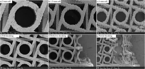
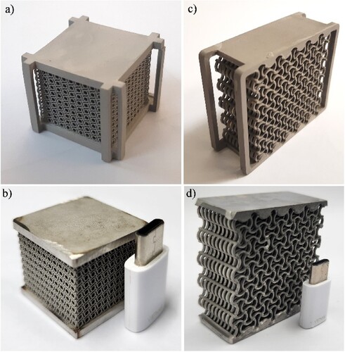
The decaking approach with the solvent spray enabled the fabrication of metallic metamaterials with micrometric lattices down to 100 µm in thickness. However, decaking of such structures on a large scale was still difficult. The mechanical metamaterials with a twist have obtained enormous attention since the proof of concept by Frenzel et al. in Science magazine [Citation39]. These innovative metamaterials convert axial loading into a rotational deformation, as illustrated in (a). We fabricated this geometry in stainless steel with a unit cell from 20 mm to 2 mm ((b)), where the 200-µm-thick walls were successfully decaked throughout the overall part. The liquid decaking also enables fabricating biomimetic spinodoid metamaterials shown in Ref. [Citation40]. These nonperiodic architectures are difficult to clean from the dry powder when using PBF and BJ due to the complex network of voids. The liquid feedstock offers better microstructure cleanability than the parts printed in dry powder bed systems. Further experimentation proved the possibility of decaking 2, 1.5 mm, and even 1 mm large cells of twist metamaterials with the size of the strut as thin as 200, 150, and 100 µm, respectively ((a–c)). Unfortunately, on a large scale such thin structures were too fragile to withstand the force induced by the solvent spray. The effect of microstructures size on the decaking of metamaterials is demonstrated on (e–g). The 2-mm large twist cells were successfully decaked throughout the thickness of the overall part ((e)). The 1.5-mm large twist cells were also fully decaked, yet the arrays of cells at the edges of the part did not withstand the spray pressure, which would be sufficient to push out the uncured feedstock, and failed in the plane perpendicular to the build orientation ((f)). Finally, the 1–mm large twist cells failed in many places with liquid feedstock being locked inside ((g)). To sum up, LMAM allows printing metamaterials with a resolution exceeding the conventional metal AM methods, such as PBF and BJ; however, the bottleneck of the technology is the insufficient strength of the green parts during decaking.
Figure 8. Simulated (with permission from Ref. [Citation39]) and printed metallic twist metamaterials using lithography metal additive manufacturing (this study).
![Figure 8. Simulated (with permission from Ref. [Citation39]) and printed metallic twist metamaterials using lithography metal additive manufacturing (this study).](/cms/asset/64ef99e6-9777-47c0-aac1-accd7ff5ced0/nvpp_a_2339368_f0008_oc.jpg)
Figure 9. The effect of microstructures size on the decaking of metamaterials printed via lithography metal additive manufacturing.
3.5. Effect of metamaterial part size on decaking process
Among the promising applications of metamaterials is weight reduction of structural components without compromising their capability to absorb and dissipate impact energy [Citation2]. Frenzel et al. [Citation39] proved that smaller twist unit cells provide higher axial-to-rotational load conversion. Meza et al. [Citation41] demonstrated that hierarchically structured metamaterials outperform the existing nonhierarchical structures in strength and stiffness when normalised by density. Thus, large metamaterial components should ideally consist of thousands of micrometric cells.
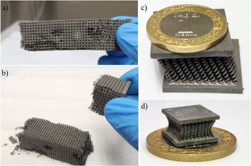
Printing parts consisting of a large number of microstructures, also known as multiscale AM [Citation3], often deal with an additional set of process issues [Citation25]. While attempting to print multiscale metamaterials, an unforeseen issue was discovered: the strength of the green microstructures was insufficient to withstand the mass of the overall part. We printed and successfully decaked a 20 × 20 × 80 mm part consisting of 4000 twist cells, but the part fell apart while handling ((a,b)). While lifting the part from the build platform, its weight exceeded its tensile strength fracturing the part at the top. When keeping the part horizontal at one end, the bending momentum exceeded the flexural strength, and the part broke in half. Putting the part on its side damaged many cells near the edge. Fabrication of other metamaterials reviewed in Ref. [Citation2] led to other integrity issue. A superelastic metamaterial consisting of a 10 × 10 array of microsprings (500-µm-thick wire with 10 spins) sloped at one side under its weight immediately after decaking and therefore could not be sintered correctly ((c)). Furthermore, when reducing the size of the microsprings twofold, they bend towards the remaining feedstock in the centre of the part ((d)). The bending is driven by the surface tension of the liquefied feedstock, suggesting that the wettability forces approach the flexural strength of the green structures. Overall, the greed microstructures cannot withstand the surface tension of the feedstock and weight of the overall part when assembled on a macroscale.
Figure 10. Insufficient strength of green microstructures when scaling up the part size in lithography metal additive manufacturing (exemplified for twist metamaterials and microsprings).
The solution for this issue consists of printing a green support frame. Conventionally, support structures are applied to maintain the overhanding features until they load on each other [Citation3]. The function of the proposed support frame is the opposite: The frame is to release the designed microstructures from loading on each other. An example of how the support structures can be realised is provided in (a). The supporting frame was safely removed after presintering at 900°C when the steel powder was reported to start fusing [Citation23]. Another example is demonstrated in (c). Such a metamaterial design appeared in the results of reconfigurability in Ref. [Citation42] and later demonstrated a negative Poisson ratio in Ref. [Citation43] and was used for designing auxetic metamaterials [Citation44,Citation45]. The green part with such auxetic architectures folds under its weight when no support frame was added. Adding the support frame allowed the entire architecture to withstand decaking and sintering.
Figure 11. Support frame as a solution for the insufficient strength of green microstructures when scaling up the part size in lithography metal additive manufacturing (exemplified for auxetic and twist metamaterials).
3.6. Effect of print orientation on the strength of green microstructures
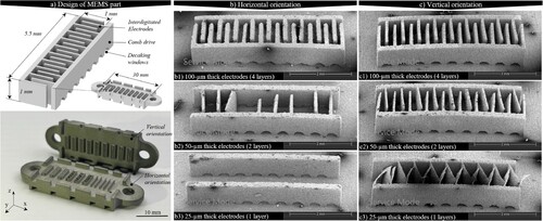
The microstructured green parts collapse in a certain direction when external force is applied impaling on anisotropic mechanical properties, which may come from print orientation. The understanding of the effect of print orientation on green part strength is critical for printing microstructures with a high aspect ratio, which is particularly important for 3D-printed electronics [Citation46] and microbatteries [Citation47,Citation48]. To study that, we designed a block of comb drives similar to those used in Refs [Citation9,Citation46,Citation47] with 20 interdigitated micro-electrodes that are 1000-µm-tall and 100, 50, or 25 µm thick, and printed them with horizontal and vertical orientations ((a)). The effect of the two print orientations on the overall structure is shown in (b,c), and the detailed observations are available in supplementary information (SI, Figure S1). The horizontally printed electrodes exhibit no deflection, irrespective of the wall thickness. Even the 25-µm-thick electrodes exhibited no bending and behaved brittle and thus were accidentally broken away from the base during decaking. Contrary to that, the vertically printed electrodes were flexible, especially 50- and 25-µm-thick electrodes were notably bent towards one another. The principal difference between the two print orientations is that the horizontally printed electrodes consist of many layers (1000-µm tall electrode /25 µm thick layer = 40 layers) whereas the vertically printed electrodes consist of just a few (100 µm thick electrode/25 µm thick layer = 4 layers). Since the first ones were rigid and the second ones were flexible, it is evident that the flexural strength of the green part increases with the number of layers. The assembly of many layers acts as a composite material, where the interfacial bonding between the layers is weaker as compared to the bonding inside the layer. A close SEM examination revealed that the delamination crack propagates at the interface between two layers. In the metal/polymer adhesive systems, the interfacial crack has lower energy consumption as compared to the cohesive crack via the bulk material [Citation49–52]. Thus, the features printed in many layers are more heterogeneous and generally weaker, whereas those consisting of a few layers are more homogenous and thus exhibit some degree of ductility before failing. In addition, the vertically printed electrodes continued the layers of the base plate and were firmly anchored to it, whereas the horizontally printed electrodes were attached to the base plate through only one fragile interface and were quickly blown away during decaking. To summarise, in-plane printing results in flexible microstructures with stronger connections, whereas multilayer structures are more brittle and fragile.
Figure 12. Effect of the 3D printing orientation on the strength of green parts in lithographic metal additive manufacturing (example of comb drives MEMS).
3.7. Effect of thermal environment on debinding process
The debinding step removes the organic content between the metallic powder through thermal evaporation and sublimation of the binder [Citation37]. Our previous thermal gravimetric analysis (TGA) and differential scanning calorimetry (DSC) of the used binder system revealed that the thermal decomposition (pyrolysis) starts at 350°C and ends at 450°C [Citation23]. A similar temperature range was reported for the complete debinding of ceramic green parts [Citation53,Citation54]. However, the debinding of ceramic parts differs from that of metallic parts due to their chemical reactivity [Citation26]. Furthermore, pyrolysing a pinch of feedstock in TGA and DSC does not necessarily represent the debinding process of a full-size 3D printed part in a furnace due to diffusive effects that may delay the pyrolysis. Here in we have evidence that the organic content can remain inside the green part until 900°C, deteriorating the surface chemistry.
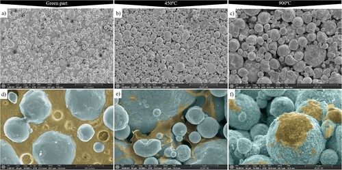
(a)–(c) depicts SEM photos of the 3D-printed part after decaking, debinding at 450°C, and presintering at 900°C, respectively, whereas photos (d)–(f) present a magnified view of the same surface. After decaking, the surface comprised binder reinforced with metallic particles ((a,d)). After debinding at 450°C, the binder was still abounding within the surface ((b) and (e)). The remaining binder spreads between the metal powder in the form of ligaments and flakes. The residual organic component above 450°C is due to the low penetration of the hydrogen gas inside the pores of the material; therefore, the hydrogen atoms could not effectively pick up carbon atoms. Further, the continuous gas flow at low pressure could not transport the carbon from the tube. Despite the residual organic mass being negligibly small, the carbon can react with the metal at a higher temperature. After presintering at 900°C, the remaining binder migrated on the sample surface in the form of carbon precipitation ((c,f)). The char residue of organic binder reacts with the oxygen to form carbon monoxide (CO) and carbon dioxide (CO2). The hydrogen atmosphere is also reactive due to methane release during binder degradation. However, the hydrogen atmosphere is less effective than the oxidising atmosphere to remove the binder. To facilitate the gas penetration and transport phenomena, a higher gas flow rate or gas purging needs to be applied in the temperature range from 350°C to 900°C by closing the valve to a vacuum pump until the gas in the tube reaches ambient pressure and then venting down to 0.1 torr. The higher gas pressure ensured a higher redox reaction rate, whereas the high volumetric flow rate ensured the carbon transport from the part. It worked well for steel parts, however may not work for more active metals, e.g. copper. Roumanie et al. [Citation26] performed debinding of copper part in the air at 400°C followed by a reduction of oxidised copper and sintering in hydrogen at 1050°C to reach a low carbon content (0.018 wt.%) similar to Cu raw powder. To mitigate the oxidation and carbonisation issue, an inert gas flow circulation with longer dwelling times and lower heating rates were recommended [Citation26]. Overall, longer debinding leads to lower carbon content.
Figure 13. The effect of temperature on surface composition during the debinding process. (d – f) Colours are graded digitally to contrast the metallic powder (blue) from the organic binder (yellow).
3.8. Effect of sintering temperature on shape stability of metamaterials
The solid-state sintering of AM parts in a furnace is a postprocessing step aimed at densifying the green part by fusing the metallic powder after removing the organic binder [Citation24]. Sintering process of steel components has been well studied in the literature devoted to fused deposition modelling (FDM) using metal-filled polymeric filaments [Citation17–21,Citation55–59]. The effect of sintering temperature on shrinkage, density, strength, and grain structures was investigated in great detail [Citation17–21,Citation55–59]. However, the 3D printed parts in those experiments had a very simple shape, e.g. centimetre-large cylinders or cubes. The typical sintering temperature for 316L steel parts varies within 1350–1400°C range [Citation17–21,Citation55–59]. Microstructured metamaterials may not withstand such temperatures and deform during sintering, which is an aspect that was not reported.
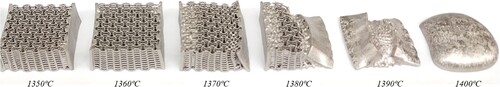
To investigate the effect of sintering temperature on shape stability of complex structures, we printed a set of auxetic metamaterials, 40 × 40 × 20 mm each, and sintered at different temperatures in the range from 1250 to 1400°C. evidences that accurate selection of the sintering temperature is crucial to preserve the shape of complex thin-walled parts. The geometries were sintered without notable deviations until 1330°C. At 1350°C the bottom and top plates of the metamaterial block started to bend. At 1360°C, the part shrank on the top more than on the bottom due to the no-slip boundary condition between the part and the holding ceramic plate. At 1370°C, the edges of the part started warping around and lattice began bending. At 1380°C, the lattice collapsed under the weight of one of the side plates. Finally, the lattice fully folded at 1390°C and turned in a single melt paddle at 1400°C under the capillary forces of molten steel. To sum up, 1330°C is the upper-temperature limit for sintering the auxetic metamaterials printed in 316L.
Figure 14. Effect of sintering temperature on the shape stability of auxetic metamaterials (40 × 40 × 20 mm each sample).
The density of the sintered metamaterials also suggests that going beyond 1330°C is not reasonable. The relative density of the sintered metamaterials were 83.4% ± 4.01%, 85.2% ± 2.03%, and 99.2% ± 0.08% at 1250°C, 1275°C, and 1300°C, respectively. Evidently, the strongest densification of about 14% happened between 1275°C and 1300°C, while further increase of sintering temperature resulted in density asymptotically approaching 100% at 1400°C. Thus, the saturation point for steel density is around 1300°C, with little to no densification benefits beyond this temperature, yet with a great risk of geometrical distortion of part’s geometry. These findings imply that the most studied temperature range for sintering 316L parts (1350–1380°C) is not applicable to geometries that make sense for 3D print. Unlike the bulky cubic and cylindrical parts often used for sintering and mechanical testing of 3D printed parts, metamaterials cannot be sintered at those temperatures and thus may not possess the previously reported stress–strain dependencies [Citation17–21,Citation55–59]. Therefore, the sintering process and mechanical properties of 3D printed parts should be studied on the geometries and scales meaningful for 3D printing.
4. Mechanical properties of the printed metamaterials
Evidently, LMAM allows printing structures representative of metamaterials; however, do those structures have ‘metaproperties’? Since the sintering of metamaterials requires a lower temperature than bulk parts, it is crucial to investigate whether the metamaterials printed via the sintering-based AM method possess their intended mechanical properties. Here in, we demonstrate the effect of sintering temperature on the performance of auxetic and twist metamaterials.
4.1. Auxetic metamaterials
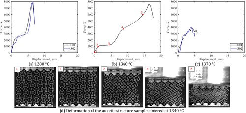
The effect of sintering temperature on the compressive response of the auxetic metamaterial is shown in . The sintering temperature affects the ultimate load (strength) of the samples and also the failure strain. At a low sintering temperature, 1280°C, the samples behave in a brittle manner, where the struts start to break after a certain strain level hence the sample loses its mechanical integrity at an early stage of loading (at displacement around 6 mm). This is due to the incomplete sintering of steel particles inside the microstructure hindering the formation of metallic grains and hence earlier cracking occurs in the struts. The SEM observations of the fractured surface after the test revealed that the metal structure sintered at 1280°C consisted of barely fused stand-alone particles (see Figure S3 in SI). Such microstructure contained extensive internal porosity due to the inter-particles voids. During mechanical loading, the voids create stress concentration within the solid phase, which is presented by micro-scaled necks of the fused particles as evidenced by the micro-fractured regions in Figure S3(a). With increasing the sintering temperature to 1340°C, good adhesion between the individual particles was transformed into 100–300 µm large metallic grains, which resulted in better deformability of the struts and thus large failure strain was achieved. Further increasing the sintering temperature to 1370°C reduced the deformability and the strength of the sample, indicating that the highest sintering temperature does not provide the highest mechanical properties of the sintered metamaterials. In the previous study [Citation23], we observed a similar tendency during the tensile testing of dog bone samples, where maximum sintering temperature resulted in the inferior stress–strain response due to the migration of certain alloying elements (Mo and S) to the grain boundaries. In other words, there is an optimal window of sintering temperature for 316L parts. This study translates the same conclusion from the regular parts, like dogbones samples, towards metamaterials. The best sintering temperature for metamaterials varies from 1300 to 1340°C, going beyond that temperature results in the atomic migration at the grain boundaries and shape distortion of the 3D printed structures due to melting. (d) demonstrates the deformability of the auxetic sample at different strain levels after sintering at 1340°C. It can be seen that with the correct sintering temperature the cells obtain the ability to deform to almost half of its initial height without breakage of the struts. Lastly, the Poisson’s ratio measured at the elastic regime (between point 1 and 2 in (b)) was negative with an average of −0.96 ± 0.04 for the three sintering temperatures. The difference between the Poisson’s ratio was insignificant in the three configurations because their elastic response was similar. The achieved value of Poisson’s ratio is comparable to those obtained via numerical simulations [Citation43] and presents considerable capability for absorbing deformation energy.
Figure 15. Effect of sintering temperature on strength of auxetic metamaterials.
4.1. Twist metamaterials
The compression test of twist materials sintered at different temperatures confirmed that those processed at 1340°C have the highest strength. For the sake of brevity, the discussion is based on these samples only. shows the compressive response of the twist metamaterial sintered at 1340°C with different architectures: a single 15-mm large cell, a column of five 15-mm large cells, and a 10 × 10 × 10 array of 2.5-mm large cells (see Figure S4 for illustration). The two samples tested for each patch behaved similarly, evidencing the precision of the printing technique for producing parts with repeatable quality. The three configurations considered behaved similarly in the elastic response, where the compression force increases monotonically with increasing displacement because the response at this stage is governed by the elastic modulus of the material. However, the response was different between the three configurations in the stage of plastic deformation. The single-cell structure twisted as expected: once the maximum rotation occurred the struts touched each other initiating the hardening effect due to the sample densification ((a)) (see video 1 in SI). When compressing the vertical column of five twist cells, some cells deformed faster than others (see video 2 in SI), which is also evidenced by several arch-like curves on the load-displacement response ((b)). The 10 × 10 × 10 array of cells twisted continuously until the weakest layers started collapsing one by one (see video 3 in SI) causing the load drops in the force–displacement response ((a)). Interestingly, at the time of collapse of the weakest layer, other layers had not reached the full rotation (see Figure S5 for illustration). This behaviour is different from the theoretically predicted one [Citation39]. The inventors of the twist metamaterial expected all cells to twist equally and simultaneously across the sample [Citation39]. However, in this experiment, we show that the manufactured metallic metamaterials at certain load points start twisting layer-by-layer. The discrepancy between the theoretical and experimental twist can be explained by the heterogeneity of the metallic microstructure across the sample. In contrast to the theoretical structures, the 3D-printed structure has inevitable microstructural defects inherited from either the fabrication or postprocessing stages. In our case, the microstructural variations could be caused in the sintering stage by a slight thermal gradient along the tube furnace. This is the first experimental evidence of how this kind of metamaterial is sensitive to structural defects due to strain localisation in the post-elastic regime.
Figure 16. Compressive response of twist metamaterials.
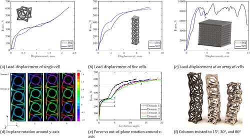
The DIC analysis allowed us to record the fact of heterogeneous twisting of steel metamaterials. The rotation of cells in the vertical column is shown in (d). Importantly, this is not the rotation around the main axis of the entire sample (z-axis) but a local rotation of each cell around its own y-axis. Since the rotation around the y-axis causes the rotation around the z-axis, the y-rotation indicates when and which cell contributed to the z-rotation of the entire structure. Thus, the rotation of each cell around its y-axis was computed at four different domains (highlighted in (d)) and at four different loads that cover the whole sample response (elastic and plastic). At a low load level within the elastic region, 200 N, the y-rotation angle of domain 1 is almost zero, while the rotation angle of domain 4 equals 0.5°. Increasing the applied load to 300 N, the domains 1 and 4 rotated to around 2°, and smaller for the domains 2 and 3, implying on non-uniform twisting. At 500 N, almost all the y-rotation angles are nearly equal at the four domains, which mean that all the material has twisted to the same degree. Evidently, the upper and lower cells of the sample were rotated faster than the cells located in the middle. The evolution of the z-rotation of the sample with respect to the applied load is shown in (e), where z-rotation of three cells reached 20° at 8 mm of compression. The maximum rotation of the entire sample consisting of five cells reached 80° ((f)). This result proves the ability of LMAM to produce twist metallic metamaterial with large deformation-to-rotation ratio.
5. Benchmarking productivity and accuracy of the method
The LMAM process allows metallic 3D architectures with a size and accuracy challenging to achieve with other AM methods. Nevertheless, this technology is only meaningful if the overall duration of the 3D printing process is acceptable to the user. This section experimentally benchmarks the accuracy of LMAM versus other metal AM methods and maps their accuracy versus productivity capabilities on a figure of merit.
The superior print accuracy of the developed LMAM over PBF is evidenced in (a,b). In this experiment, we used a Lasertech 30 dual SLM second-generation 3D printing unit (DMG Mori, Bielefeld, Germany), which is positioned to fabricate fine parts, such as impellers and dental crowns. The stainless steel feedstock, process parameters, inclined part orientation, and other conditions were set as recommended by the vendor. The printed twist metamaterial is depicted in (a). First, the geometry was distorted due to the thermally induced stresses at the upper edges of the workpiece. Fair to remark, that this distortion can be mitigated by increasing the time delay between layers, reducing the temperature accumulation. However, a more significant problem was found during microscopic observation of the part geometry. The unit cell of the twist metamaterials contained geometrical defects. The linear elements designed to enable the twist motion between the cells largely overlapped due to excessive fusion. Such overlaps limit the extent of possible elastic deformation that reduces the twist function of the metamaterial, if not disables it at all. The twist metamaterials printed on the same scale as steel via LMAM are illustrated in (b). The LMAM method provides superior accuracy compared to state-of-the-art PBF systems.
Figure 17. Comparing the print accuracy of (a) selective laser melting to (b) lithography metal additive manufacturing and (c) surface roughness of binder jetting to (d) lithography metal additive manufacturing.
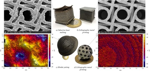
The accuracy advantages of LMAM over BJ are illustrated in (c,d). These may be the only two technologies allowing the printing of metallic parts inside other parts. Again, LMAM allows notably refined accuracy and, thus, the part design. In this experiment, we used perhaps the most researched BJ system ExOne 100 (Desktop Metal, Massachusetts, US) to print a 50-mm perforated sphere with a 10-mm sphere inside (visualised inside the sphere in (c)). However, the internal sphere was impossible to clean from the clogged powder inside; thus, it was sintered as a completely filled steel ball. In contrast, LMAM exhibits no such limitations to the internal part. We designed a 20-mm perforated sphere with a 2-mm-thick shell and placed inside it the same sphere but scaled down to 50% (a 10-mm perforated sphere with a 1-mm-thick shell) as depicted in (d). Both spheres were fully decaked and sintered. After sintering, the smaller sphere was visually confirmed to roll inside the larger one. The liquid feedstock is easier to remove from the internal green structures than the dry powder. Thus, compared to BJ, LMAM allows for broader and finer design freedom for parts that replace complex assemblies with internal parts.
Another advantage of LMAM over BJ is the reduced surface roughness. We used an optical profiler (Zygo 7200, Middlefield, US) to scan the surface of both spheres after sintering and filtered the spherical curvature digitally (as proposed by Michigan Metrology [Citation60]) to quantify the areal surface roughness according to the ISO 25718-2 standard. The lithographic parts appeared nearly three times smoother than BJ parts (Sa = 5.6 µm vs Sa = 14.8 µm, respectively). Due to the protruding particles, the surface of BJ parts contains pits and depressions, sometimes exceeding the overall magnitude of 100 µm ((c)), limiting the minimal feature size and geometrical tolerance (e.g. in fitting applications). Compared to that, the surface of LMAM parts consists of protruding layers, the magnitude of which does not exceed 25 µm (due to layer thickness). The protruding layers appear as the diagonally oriented texture in (d). The circular pattern is due to the spherical shape of the surface, which was digitally filtered following the procedure in Ref. [Citation28]. Besides the improved geometrical accuracy of the surface, the lower roughness allows better fitting control, minimal postprocessing, and a more aesthetic appearance directly from the furnace.
Hahn et al. [Citation9] introduced a figure of merit plotting the voxel size versus the printing rate and volume to map the productivity versus accuracy of various AM processes. We mapped the LMAM process in the figure () to benchmark it versus other AM methods, such as electron beam-induced deposition, selective laser sintering, electrohydrodynamic printing, direct ink writing, fused filament fabrication, inkjet printing, projection microstereolithography, continuous liquid interphase printing, computed axial lithography, and two-photon printing. Although Hahn et al. [Citation22] revealed that some of these points are theoretical and not achievable in practice, LMAM competes in many of these processes. The achieved and potential LMAM performances are mapped with black and dark rectangles, respectively. Compared to LMAM, selective laser sintering is an order of magnitude less accurate. Inkjet printing requires 15,192 nozzles to perform on a similar level, whereas projection microstereolithography and direct ink writing are too slow. Finally, LMAM can be realised via other SLA systems; thus, the large field of two-photon lithography should be considered an opportunity for an extension rather than a complete technology.
Figure 18. Map of productivity vs accuracy of additive manufacturing technologies (reproduced with permission from Ref. [Citation22]). 2PP: two-photon lithography, EBID: electron beam-induced deposition, SLS: selective laser sintering, EHDP: electrohydrodynamic printing, DIW: direct ink writing, FFF: fused filament fabrication, IJ: inkjet printing, (Pμ)SL: projection microstereolithography, CLIP: continuous liquid interphase printing, CAL: computed axial lithography, LMAM: lithography metal additive manufacturing.
![Figure 18. Map of productivity vs accuracy of additive manufacturing technologies (reproduced with permission from Ref. [Citation22]). 2PP: two-photon lithography, EBID: electron beam-induced deposition, SLS: selective laser sintering, EHDP: electrohydrodynamic printing, DIW: direct ink writing, FFF: fused filament fabrication, IJ: inkjet printing, (Pμ)SL: projection microstereolithography, CLIP: continuous liquid interphase printing, CAL: computed axial lithography, LMAM: lithography metal additive manufacturing.](/cms/asset/06abc548-60d8-4685-b8d0-e2c58193fcf3/nvpp_a_2339368_f0018_oc.jpg)
Ideally, the same type of benchmark structure should have been 3D printed using different metal AM methods, allowing for a direct and fair comparison. However, the field has not yet reached that level of maturity [Citation22]. In addition, the advantages of one method often appear with conditions of operational incapability in other methods. For instance, the high productivity of directed energy deposition (including thermal [Citation61] and cold spray [Citation62]) appears in a size scale unreachable for electron beam melting and vice versa for accuracy. Thus, metal AM methods cannot replace each other but dominate in a particular scale and application domain. Considering the available experience, we qualitatively classify the LMAM technology relative to other metal AM, as presented in . The table reveals that LMAM is a good compromise between productivity, accuracy, and part size, ensuring the multiscale printing capability of the method. In addition, LMAM is notably safer, energy efficient and cheaper than the closest competitor, SLM.
Table 1. Comparison of widely used metal additive manufacturing technologies with lithography metal additive manufacturing.
6. Conclusions
This study delivers a multiscale metal printing technology, named LMAM, for the manufacturing of metallic metamaterials with high accuracy and precision. Here in, we investigated the physical phenomena of the LMAM process, discovered and solved new technological challenges when scaling up the process, tested the quality of produced metamaterials, and benchmarked the proposed AM method versus existing ones specifically for the production of metamaterials. Our findings support the following conclusions:
Metal-filled resin undergoes geometrical overpolymerisation during exposure. The lateral overpolymerisation results in nearly 50–70 µm of geometrical overgrowth of green parts. The overgrowth can be reduced to 5–10 µm by introducing a digital contour offset with a predetermined value.
Metal-filled resin undergoes phase segregation when liquefied inhibiting structural support during printing and feedstock reuse. The sedimentation of metal powder in resin can be eliminated by introducing a thermal softening agent (wax) in the feedstock and dual temperature control during printing.
Decaking of microstructured parts is a bottleneck of the LMAM technology. Pressurised spraying of hot solvent-based solution doped with soap and surface-active agents eases the issue.
Green microstructures assembled on a macroscale cannot withstand their weight. A temporary support frame can be printed around a microstructured part to carry the part’s weight and removed after sintering.
Print orientation affects the strength of the green microstructures. The microstructures are flexible or brittle when printed parallel or perpendicularly to the layers, respectively.
A small percentage of organic binder remains inside the parts up to 900°C. Gas purging with altered pressure can be applied in the debinding stage to remove the binder from the pores of the green parts.
Powder clogging inhibits printing microstructured parts enclosed inside other parts using powder bed systems. The proposed solid–liquid-phase changing feedstock enables the printing and decaking of parts designed inside other parts.
The higher the temperature the better is not true for the sintering of 316L stainless steel metamaterials. The best sintering temperature varies from 1300 to 1340°C, going beyond that temperature deteriorates the strength and shape of metamaterials.
The mechanical metamaterials, such as auxetic and twist, are sensitive to microstructural defects in the printed metal. As opposed to the FEM simulations and metamaterials made of polymers, the metamaterials made of steel can deform heterogeneously and sequentially across their structure. Homogeneous sintering is of paramount importance for the quality of metallic metamaterials.
The benchmarking experiments reveal that the proposed LMAM method competes with SLM and BJ in accuracy, surface roughness, and design freedom while retaining an average-range print size (90 × 56 × 120 mm).
The proposed technological solutions allowed the printing of various microstructured metallic metamaterials, such as photonic spanning helixes, arrays of microsprings, parts in parts, auxetic metamaterials, twist metamaterials, and triply periodic minimal surfaces reaching a decimetre scale. To our knowledge, this is the first successful attempt to do such metamaterials in stainless steel and test their performance. The capability to manufacture such materials and designs is the key to redesigning the existing structures and unlocking the evolution of functional materials and new devices.
Supplemental Material
Download MS Word (7.1 MB)Disclosure statement
No potential conflict of interest was reported by the author(s).
Data availability statement
The authors confirm that the data supporting the findings of this study are available within the article and its supplementary materials. Raw DIC data were generated within the MCEM lab at KAUST. Derived data supporting the findings of this study are available from the corresponding authors on request.
References
- Kinsler P, McCall MW. The futures of transformations and metamaterials. Photonics Nanostruct Fundam Appl. 2015;15:10–23. doi: 10.1016/j.photonics.2015.04.005
- Kadic M, Milton GW, Wegener M. 3D metamaterials. Nature. 2019;1:198–210. doi: 10.1038/s42254-018-0018-y
- Thompson MK, Moroni G, Vaneker T, et al. Design for additive manufacturing: trends, opportunities, considerations, and constraints. CIRP Ann Manuf Technol. 2016;65:737–760. doi: 10.1016/j.cirp.2016.05.004
- Zhakeyev A, Wang P, Zhang L, et al. Additive manufacturing: unlocking the evolution of energy materials. Adv Sci. 2017;4:1–44. doi: 10.1002/advs.201700187
- Jiao P, Mueller J, Raney JR, et al. Mechanical metamaterials and beyond. Nat Commun. 2023;14:6004. doi: 10.1038/s41467-023-41679-8
- Gao S, Li Z, Van Petegem S, et al. Additive manufacturing of alloys with programmable microstructure and properties. Nat Commun. 2023;14:6752. doi: 10.1038/s41467-023-42326-y
- Zhang J, Xiao M, Gao L, et al. Self-bridging metamaterials surpassing the theoretical limit of Poisson’s ratios. Nat Commun. 2023;14:1–8. doi: 10.1038/s41467-023-39792-9
- Gansel JK, Thiel M, Rill MS, et al. Gold helix photonic metamaterial as broadband circular polarizer. Science. 2009;325:1513–1516. doi: 10.1126/science.1177031
- MacDonald E, Wicker R. Multiprocess 3D printing for increasing component functionality. Science. 2016;353:1512–1522. doi: 10.1126/science.aaf2093
- Chen XZ, Liu JH, Dong M, et al. Magnetically driven piezoelectric soft microswimmers for neuron-like cell delivery and neuronal differentiation. Mater Horizons. 2019;6:1512–1516. doi: 10.1039/c9mh00279k
- Qin J, Hu F, Liu Y, et al. Research and application of machine learning for additive manufacturing. Addit Manuf. 2022;52:1–25. doi: 10.1016/j.addma.2022.102691
- T. Wohlers, T. Gornet, History of additive manufacturing. Wohlers report 2016. 2016. doi: 10.4018/978-1-5225-2289-8.ch001
- Harinarayana V, Shin YC. Two-photon lithography for three-dimensional fabrication in micro / nanoscale regime : a comprehensive review. Opt Laser Technol. 2021;142:107180. doi: 10.1016/j.optlastec.2021.107180
- Raoelison RN, Xie Y, Sapanathan T, et al. Cold gas dynamic spray technology: a comprehensive review of processing conditions for various technological developments till to date. Addit Manuf. 2018;19:134–159. doi: 10.1016/j.addma.2017.07.001
- Yin S, Cavaliere P, Aldwell B, et al. Cold spray additive manufacturing and repair: fundamentals and applications. Addit Manuf. 2018;21:628–650. doi: 10.1016/j.addma.2018.04.017
- Raoelison RN, Verdy C, Liao H. Cold gas dynamic spray additive manufacturing today: deposit possibilities, technological solutions and viable applications. Mater Des. 2017;133:266–287. doi: 10.1016/j.matdes.2017.07.067
- Wang F, You S, Jiang D, et al. Microstructure evolution, phase formation, corrosion, and mechanical properties of stainless steel fabricated by extrusion-based sintering-assisted additive manufacturing. Addit Manuf. 2023;75:103746. doi: 10.1016/j.addma.2023.103746
- You S, Jiang D, Wang F, et al. Anisotropic sintering shrinkage behavior of stainless steel fabricated by extrusion-based metal additive manufacturing. J Manuf Process. 2023;101:1508–1520. doi: 10.1016/j.jmapro.2023.07.026
- Thompson Y, Gonzalez-Gutierrez J, Kukla C, et al. Fused filament fabrication, debinding and sintering as a low cost additive manufacturing method of 316L stainless steel. Addit Manuf. 2019;30:100861. doi: 10.1016/j.addma.2019.100861
- Damon J, Dietrich S, Gorantla S, et al. Process porosity and mechanical performance of fused filament fabricated 316L stainless steel. Rapid Prototyp J. 2019;25:1319–1327. doi: 10.1108/RPJ-01-2019-0002
- Sadaf M, Bragaglia M, Nanni F. A simple route for additive manufacturing of 316L stainless steel via Fused Filament Fabrication. J Manuf Process. 2021;67:141–150. doi: 10.1016/j.jmapro.2021.04.055
- Hahn V, Kiefer P, Frenzel T, et al. Rapid assembly of small materials building blocks (Voxels) into large functional 3D metamaterials. Adv Funct Mater. 2020;30:1–9. doi: 10.1002/adfm.201907795
- Melentiev R, Harakály G, Stögerer J, et al. High-resolution metal 3D printing via digital light processing (submitted). Addit Manuf. 2024:1–13.
- Bourell D, Kruth JP, Leu M, et al. Materials for additive manufacturing. CIRP Ann Manuf Technol. 2017;66:659–681. doi: 10.1016/j.cirp.2017.05.00
- Nguyen HX, Suen H, Poudel B, et al. Development of an innovative, high speed, large-scaled, and affordable metal additive manufacturing process. CIRP Ann Manuf Technol. 2020;69:177–180. doi: 10.1016/j.cirp.2020.04.069
- Roumanie M, Flassayer C, Resch A, et al. Influence of debinding and sintering conditions on the composition and thermal conductivity of copper parts printed from highly loaded photocurable formulations. SN Appl Sci. 2021;3:1–11. doi: 10.1007/s42452-020-04049-3
- Melentiev R, Lubineau G. Large-scale hot embossing of one-micron high-aspect-ratio textures on ABS polymer. CIRP J Manuf Sci Technol. 2022;38:340–349. doi: 10.1016/j.cirpj.2022.05.011
- Melentiev R, Kang C, Shen G, et al. Study on surface roughness generated by micro-blasting on Co-Cr-Mo bio-implant. Wear. 2019;428–429:111–126. doi: 10.1016/j.wear.2019.03.005
- Mitteramskogler G, Gmeiner R, Felzmann R, et al. Light curing strategies for lithography-based additive manufacturing of customized ceramics. Addit Manuf. 2014;1-4:110–118. doi: 10.1016/j.addma.2014.08.003
- Kolb C, Lindemann N, Wolter H, et al. 3D-printing of highly translucent ORMOCER®-based resin using light absorber for high dimensional accuracy. J Appl Polym Sci. 2021;138:1–12. doi: 10.1002/app.49691
- Vaezi M, Seitz H, Yang S. A review on 3D micro-additive manufacturing technologies. Int J Adv Manuf Technol. 2013;67:1721–1754. doi: 10.1007/s00170-012-4605-2
- Maleki E, Bagherifard S, Bandini M, et al. Surface post-treatments for metal additive manufacturing : progress, challenges, and opportunities. Addit Manuf. 2021;37:101619. doi: 10.1016/j.addma.2020.101619
- Catchpole-Smith S, Sélo RRJ, Davis AW, et al. Thermal conductivity of TPMS lattice structures manufactured via laser powder bed fusion. Addit Manuf. 2019;30:100846. doi: 10.1016/j.addma.2019.100846
- Carolo LCB. A review on the influence of process variables on the surface roughness of Ti-6Al-4V by electron beam powder bed fusion. Addit Manuf. 2022;59:103103. doi: 10.1016/j.addma.2022.103103
- Zhao X, Zhao Y, Li MD, et al. Efficient 3D printing via photooxidation of ketocoumarin based photopolymerization. Nat Commun. 2021;12:1–8. doi: 10.1038/s41467-021-23170-4
- Ozkan B, Sameni F, Goulas A, et al. Hot ceramic lithography of silica-based ceramic cores: the effect of process temperature on vat-photopolymerisation. Addit Manuf. 2022;58:1–17. doi: 10.1016/j.addma.2022.103033
- Hu K, Zhao P, Li J, et al. High-resolution multiceramic additive manufacturing based on digital light processing. Addit Manuf. 2022;54:102732. doi: 10.1016/j.addma.2022.102732
- Ng CS, Subramanian AS, Su PC. Zinc oxide nanoparticles as additives for improved dimensional accuracy in vat photopolymerization. Addit Manuf. 2022;59:103118. doi: 10.1016/j.addma.2022.103118
- Frenzel T, Kadic M, Wegener M. Three-dimensional mechanical metamaterials with a twist. Science. 2017;358:1072–1074. doi: 10.1126/science.aao4640
- Kumar S, Tan S, Zheng L, et al. Inverse-designed spinodoid metamaterials. npj Comput Mater. 2020;6:1–10. doi: 10.1038/s41524-020-0341-6
- Meza LR, Zelhofer AJ, Clarke N, et al. Resilient 3D hierarchical architected metamaterials. Proc Natl Acad Sci USA. 2015;112:11502–11507. doi: 10.1073/pnas.1509120112
- Xia X, Afshar A, Yang H, et al. Electrochemically reconfigurable architected materials. Nature. 2019;573:205–213. doi: 10.1038/s41586-019-1538-z
- Wang H, Zhang Y, Lin W, et al. A novel two-dimensional mechanical metamaterial with negative Poisson’s ratio. Comput Mater Sci. 2020;171:109232. doi: 10.1016/j.commatsci.2019.109232
- Lei M, Hong W, Zhao Z, et al. 3D Printing of auxetic metamaterials with digitally reprogrammable shape. ACS Appl Mater Interfaces. 2019;11:22768–22776. doi: 10.1021/acsami.9b06081
- Kochmann DM, Bertoldi K. Exploiting microstructural instabilities in solids and structures: from metamaterials to structural transitions. Appl Mech Rev. 2017;69:1–24. doi: 10.1115/1.4037966
- Flowers PF, Reyes C, Ye S, et al. 3D printing electronic components and circuits with conductive thermoplastic filament. Addit Manuf. 2017;18:156–163. doi: 10.1016/j.addma.2017.10.002
- Pang Y, Cao Y, Chu Y, et al. Additive manufacturing of batteries. Adv Funct Mater. 2020;30:1–22. doi: 10.1002/adfm.201906244
- Pikul JH, Gang Zhang H, Cho J, et al. High-power lithium ion microbatteries from interdigitated three-dimensional bicontinuous nanoporous electrodes. Nat Commun. 2013;4:1–5. doi: 10.1038/ncomms2747
- Melentiev R, Lagerweij A, Lubineau G. Multiprocess additive manufacturing via fused deposition modeling, chemical deposition, and electroplating with tough interfacial adhesion. Smart Mater Manuf. 2024;2:100043. doi: 10.1016/j.smmf.2023.100043
- Melentiev R, Tao R, Lubineau G. Greener electrochemical plating of ABS polymer with unprecedented adhesion via hierarchical micro-nano texturing. J Mater Res Technol. 2023;24:3575–3587. doi: 10.1016/j.jmrt.2023.04.001
- Melentiev R, Tao R, Li X, et al. Mapping the coating failure modes of electroless plated metal on ABS polymer with micro-nano structured interface. Int J Adhes Adhes. 2023;126:103471.
- Yudhanto A, Li X, Tao R, et al. Identifying adhesion characteristics of metal-polymer interfaces : recent advances in the case of electroplated acrylonitrile butadiene styrene. Mater Today Commun. 2023;35:106218. doi: 10.1016/j.mtcomm.2023.106218
- Kotz F, Arnold K, Bauer W, et al. Three-dimensional printing of transparent fused silica glass. Nature. 2017;544:337–339. doi: 10.1038/nature22061
- Zhang G, Wu Y. Three-dimensional printing of transparent ceramics by lithography-based digital projection. Addit Manuf. 2021;47:102271. doi: 10.1016/j.addma.2021.102271
- Santamaria R, Salasi M, Bakhtiari S, et al. Microstructure and mechanical behaviour of 316L stainless steel produced using sinter-based extrusion additive manufacturing. J Mater Sci. 2022;57:9646–9662. doi: 10.1007/s10853-021-06828-8
- Caminero MÁ, Romero A, Chacón JM, et al. Rodríguez, Additive manufacturing of 316L stainless-steel structures using fused filament fabrication technology: mechanical and geometric properties. Rapid Prototyp J. 2021;27:583–591. doi: 10.1108/RPJ-06-2020-0120
- Quarto M, Carminati M, D’Urso G. Density and shrinkage evaluation of AISI 316L parts printed via FDM process. Mater Manuf Process. 2021;36:1535–1543. doi: 10.1080/10426914.2021.1905830
- Jiang D, Ning F. Additive manufacturing of 316L stainless steel by a printing-debinding-sintering method: effects of microstructure on fatigue property. J Manuf Sci Eng Trans ASME. 2021;143:1–10. doi: 10.1115/1.4050190
- Ait-Mansour I, Kretzschmar N, Chekurov S, et al. Design-dependent shrinkage compensation modeling and mechanical property targeting of metal FFF. Prog Addit Manuf. 2020;5:51–57. doi: 10.1007/s40964-020-00124-8
- Michigan Metrology. Surface Texture Parameters Glossary; 2014. p. 1–102.
- Melentiev R, Yudhanto A, Tao R, et al. Metallization of polymers and composites : state-of-the-art. Mater Des. 2022;221:1–36. doi: 10.1016/j.matdes.2022.110958
- Melentiev R, Yu N, Lubineau G. Polymer metallization via cold spray additive manufacturing: a review of process control, coating qualities, and prospective applications. Addit Manuf. 2021;48:102459. doi: 10.1016/j.addma.2021.102459