
 ?Mathematical formulae have been encoded as MathML and are displayed in this HTML version using MathJax in order to improve their display. Uncheck the box to turn MathJax off. This feature requires Javascript. Click on a formula to zoom.
ABSTRACT
The objective of this work is to study the effects of different coating materials (black paint, thermoplastic elastomers, black vinyl tape and uncoated surfaces) in Laser Shock Peening (LSP) processing of laser powder bed fusion (L-PBF) printed thin AlSi10Mg tubes. The investigations were carried out with pre-identified optimal LSP parameters for the AlSi10Mg material. The study was performed using an analysis of surface residual stresses, where a maximum compressive stress of −85 MPa has been reached, while the depth of the compressive regime stays till 2 mm. The microstructural study reveals the multifold dislocation of the grains and formation of new sub-grains, thus changing the grain boundaries in all experiments due to lattice strain development by LSP. Microhardness has also shown alteration after LSP and accounted for a 5–15% increase in it after LSP. Surface properties, such as roughness and volumetric parameters, have also shown changes after LSP processing.
1. Introduction
Laser shock peening (LSP) is a surface/subsurface modification method that has been shown to significantly extend the fatigue life of processed parts [Citation1]. A high-intensity laser pulse is used to ablate the material surface, resulting in the creation of plasma [Citation2]. As the plasma expands, shockwaves propagate deeper into the material, with plasma durations typically measured in nanoseconds. The material permanently deforms at a high strain rate, presuming that the shockwave intensity exceeds the treated material's Hugenistic Elastic Limit (HEL) [Citation3]. Shockwaves are naturally attenuated further into the material, yet the treatment often affects far greater depths than the more well-known industrial shot peening [Citation4]. To prevent free expansion of the plasma an optically transparent tamping layer is used (most often water, in some cases oil or glass) driving the pressure into the material increasing the efficiency of the processing [Citation5]. The LSP processing is most often done with the use of sacrificial coating [Citation6]. This layer absorbs the laser pulse and protects the treated surface from thermal and ablative impacts, while still allowing shockwaves to transmit and propagate through the materials. The generated shockwave must pass through the additional boundary, which affects shockwave propagation. If the sacrificial coating is not employed, the physical consequences of the high-pressure, high-temperature plasma on the treated surface will be seen, and the process cannot be technically classified as ‘cold working’. Furthermore, heat impacts reduce the surface quality of the treated portion [Citation7].
From the industrial point of view, the use of sacrificial coating has significant importance over the quality and productivity of the process. When no sacrificial coating is used, the thermal effects usually result in increased roughness and tensile residual stresses on the thin topmost layer which fall quickly into the compressive regime [Citation8]. While using a sacrificial layer, the processing results in better roughness and compressive residual stresses starting from the surface layer of the treated sample which is regarded as highly beneficial for the fatigue life [Citation9]. The processing time is nonetheless increased as the sacrificial coating has to be reapplied as it is perpetually being damaged by the incoming laser pulses [Citation10]. The sacrificial coating can withstand only a certain amount of accumulated laser intensity, which is exceeded by the processing, especially when overlapping the laser spots. Multiple works are describing using different sacrificial coatings. Black vinyl tape is used most often as it is quick to apply; however. the tape does not stick to surfaces with high roughness and convoluted geometries (e.g. additively manufactured parts). Aluminium tape is sometimes used as it can withstand more laser intensity, but the same limitations as with the vinyl tape apply. Black paint is overcoming these issues as it can adhere to high roughness and convoluted geometries, yet the processing time is prolonged even further as it must be applied in several coats (especially for intricate shape geometries to avoid paint spalling) and the time for drying must be accounted for as well.
For commercial applications, the LSP process must shift towards processing a higher volume of parts while also lowering processing costs to become more industrially viable. Cost and quality factors must be investigated; this necessitates an in-depth look into many components of LSP, with sacrificial coatings being a prominent player. A few publications focus on the industrial elements of processing and compare various techniques to sacrificial coatings [Citation11]. Some of the worth mentioning literature include Sundar et al. [Citation12] used LSP with paint and black PVC tape as a sacrificial layer on steel and titanium flat tensile specimens and found that the vinyl tape performed similarly to paint on Ti6Al4 V titanium alloy, SAE 9260 spring steel and DIN X20Cr13 stainless steel. Yella et al. [Citation13] explored the performance of LSP without coating and LSP with transparent, absorbent and black tape on the 304 stainless steel with a focus on laser energy in relation to surface roughness and surface residual stress. Sanchez et al. [Citation14] compared the fatigue life of AA7075 LSP processed with and without a protective ablation layer and found an increase of 400% fatigue life on the pre-corroded specimens when processed with LSP without coating and an increase of 250% when utilising LSP with coating. Laurençon et al. [Citation15] studied the dynamic response of AlSi10Mg produced by the SLM additive manufacturing subjected to shock loading where they described the anisotropy of the material properties (elastic limit, spall strength) in relation to building orientation. Pavan et al [Citation16] studied fatigue crack growth of LSP-processed conventional aluminium for use in aerospace where they reported an increase in fatigue life by a factor of 4 as compared to unpeened specimens. Similarly, Dhakal and Swaroop [Citation17] focused on the mechanical and microstructural interactions of LSP and the 6061-aluminium alloy reporting microstructural refinement and precipitation-driven strengthening. A hybrid LSP with additive manufacturing has been proposed by Kalentics et al [Citation18] concluding a possibility to alter and control the microstructure and mechanical properties in the volume of the AM parts. Wu et al. studied the behaviour of crack development by in-situ X-ray tomography on hybrid 3D LSP-processed AlSi10Mg specimens [Citation19]. Surface parameters of LSP processed and additively manufactured Titanium Ti6Al4 V were correlated to friction and wear by Zhou et al. [Citation20] achieving a significant reduction in mass loss by 50%. Various post-processing methods for additive-manufactured metals have been reviewed by Ye et al [Citation21]. A more industrially focused overview of LSP has been created by Claure [Citation22] over the development of LSP as a whole technology. Wu et al. described the use-cases and possible penetration into the railway marked [Citation23].
It is evident from the literature that the mechanism of using sacrificial coatings is still not fully explored and especially its behaviour on additively manufactured parts does not have any substantial discussions. Thus, considering the complexity of the AM parts, the present work is focused on exploring the effects of different coating materials in LSP for L-PBF printed AlSi10Mg thin tubes. The thin-walled structures, which are often the resulting geometry of weight reduction when using AM, have increased the complexity of the presented problem. The specimen geometry also represents non-planar scenarios, further complicating the application of sacrificial coatings and posing additional challenges as the simultaneous double-side processing is a complex task in LSP when treating small diameter tubes. Experiments were conducted on pre-identified optimal LSP parameters for the material [Citation24], while the outcome of the present research was analysed in terms of surface residual stresses, depth profile, crystallography, microstructural and microhardness studies and surface properties (i.e. surface roughness and waviness).
2. Materials and method
The L-PBF printed thin-walled structures which are inherently more complex to process with LSP as the shockwave reflection from the back surface interferes with the incoming shockwave and interference occurs. To combat these issues a technique of splitting the laser beam and processing both sides of the sample at once, thus eliminating the issue of interference, can be employed. In engineering applications, this technique can be, however, non-viable due to geometry constraints permitting the laser delivery to both sides at once. More issues arise when thinking about engineering applications of LSP, mainly when leaving the most traditional flat plates sample geometry as geometrical complexity plays a significant role in the successful application of sacrificial coating. Tapes have the tendency to wrinkle over the surface with sudden changes in normal vectors, or tapes overlap when applied over round bars which can create discrepancies in the processed properties of the sample.
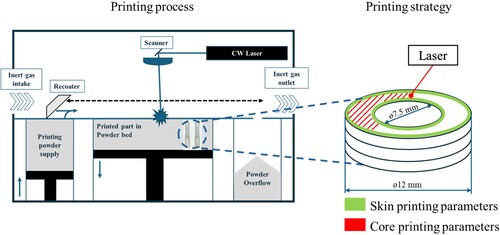
Considering the above-mentioned limitations, a thin-walled, hollow cylinder geometry was selected. The samples of 12 mm outer and 7.5 mm inner diameter were printed in the vertical orientation. L-PBF printing has been done on the Concept Laser M2 Cusing machine in the nitrogen atmosphere from recycled AlSi10Mg material, commercially available as CL31AL. The printing parameters used were recommended by the manufacturer for the efficient printing of AlSi10Mg material. During the contour printing, the laser power was set to 200 W, 50-micrometer spot size, scattered on the buildplate at 350 mm/s as scanning speed. Similarly, a laser power of 370 W, a greater spot size of 190 micrometers has been scattered at 1400 mm/s of scanning speed when printing the core of the sample. The trace spacing of 0.112 mm from the original contour of 0.175 mm with a layer thickness of 25 micrometres, a schematic of the printing is presented in .
Figure 1. Schematics of the L-PBF process.
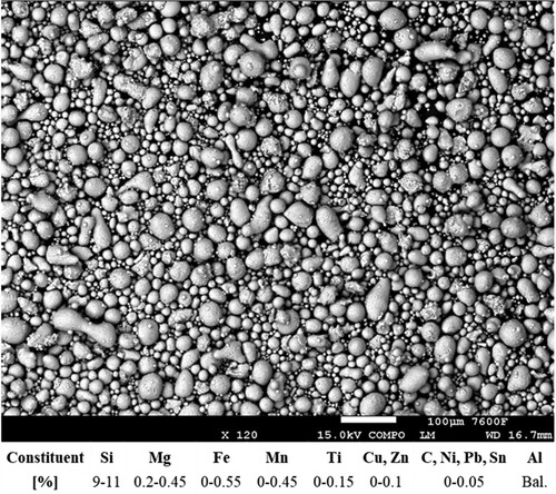
Powder characterisation showed () compliance with the chemical composition stated by the powder manufacturer, yet the size distribution lay outside the measurement error. Larger powder particles are present either due to imperfect material recycling or due to divergence in the powder production process. The guidelines and recommendations of the producer were followed for heat treatment after the printing process before removing the samples from the build plate, characterisation, LSP processing and final characterisation.
Figure 2. Powder characteristics.
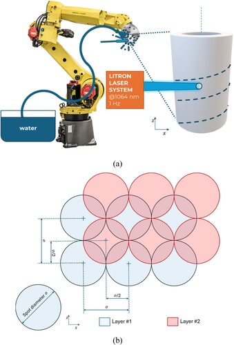
Laser shock peening was done using Litron laser LPY ST 7875 which produces laser pulses with top-hat profile at 1 Hz or 10 Hz, 1064 nm and 17 ns with circular beam shape. For the precise control and movement of the samples, a robotic arm Fanuc M-20iB 35S with a load carrying capacity of 35 kg was used. The peening configuration used for the present experiments is depicted in a. For the experiments pulse energy of 1 J, spot size of 1.15 mm diameter resulting in the power density of 5.67 GW/cm2 was utilised with the strategy of two overlapping layers, as presented in b. As a confining layer, a thin overlay of around 2 mm of laminar waterflow was used.
Figure 3. Schematic representation of (a) LSP processing and (b) Layering and overlap.
Four different conditions for LSP were used by changing the material of sacrificial coatings, as presented in . The stresses have been measured by a Rigaku Auto MATE-II X-ray diffractometer. A copper anode, measuring 6 ψ angles between 0 and 45 degrees, was used for the measurement and all the measurements were done using the sin2ψ method. The 2-theta angle for the AlSi10Mg material was 137.5 degrees. X-ray diffraction peak data were obtained using a Rigaku SmartLab scientific- grade X-ray diffractometer. For quantitative analysis, the powder XRD software of SmartLab studio was used. While analysing data, instrumental broadening was taken into account.
Table 1. Details of input variables, calculated values and measured surface residual stresses.
The confocal microscope Mahr CM Expert accompanied by Mountains Map software was used for the roughness measurement. The area of 4.21 mm × 315.3 µm was scanned in accordance with ISO 4288, and a Gaussian S-filter of 2.5 µm and a Gaussian L-filter of 0.8 mm were used. Every 25 points a profile has been evaluated providing additional stability to the measurement.
The porosity has been evaluated through the Computed Tomography machine by Zeiss Metrotom 1500 with VG Studio Max software. The machine has been set to 200 kV voltage, 112 µA current and 10.09 magnification which resulted in 22 µm spot, natural voxel size of 19.82 µm. A total of 1100 projections were continuously scanned and evaluated. The detected defects were considered porosity when detected larger than 8 voxels and probability over 1.3. Furthermore, microstructure evaluation was performed using the Tescan FE-SEM machine by which the scanning electron microscopy evaluation (SEM), backscattered diffractometer (EBSD) and kernel misorientation mappings (KAM) were acquired. The samples have been cut, cast into cold epoxy and softly mechanically polished using SiC to Oxide Polishing Suspension (OP-S), non-dry using minimum load ranging from 10N to 20N in such a manner that the residual stresses have not been altered. Chemical etching utilising a solution of was effectuated as a last step in sample preparation. Microhardness testing was done on the polished cross-section using an ARS-FM machine with a controller. The load of 50 gf was applied while following the ISO 6507 standard.
3. Results and discussion
Numerous models predict the behaviour of LSP. The most often used is one of the simplest, developed by Peyer et al. [Citation28] for the calculation of peak pressure :
(1)
(1) where α represents the efficiency of the interaction (typically 0.25),
the Incident laser power density and
represents reduced shock impedance for which the following equation applies:
(2)
(2) Furthermore, the fraction of energy that is reflected is given by the reflection coefficient, R:
(3)
(3) The LSP process can be effective only when the induced pressure shockwave crosses the dynamic yield limit [usually measured in terms of Hugoniot elastic limit (HEL)] to inflict permanent plastic deformation within the material [Citation29]. The Hugoniot elastic limit (HEL) is specific for each material, and for uniaxial strain state can be calculated as
(4)
(4) where
is the dynamic yield strength of the material and
is the Poisson’s ratio. [Citation13]. For AM-printed aluminium a value of HEL as 300 MPa has been considered [Citation15].
As the coating material is not fully ablated, the propagating shockwaves pass through the thickness of the coating. The total impedance is thus modified [Citation30]
(5)
(5) Equation (1) for peak pressure
is altered:
(6)
(6) presents the details of all four different experimental conditions and values of longitudinal surface residual stresses. The values of acoustic impedance and peak pressure calculated using Equation 1 and 2 are presented for Case #2, e.g. the Case with no sacrificial coating. For Cases #1, #3 and #4 where the coating protects the treated surface from direct interaction with the laser pulse, the modified Equations (5) and (6) were used.
It can be observed from that the maximum pressure of 3270 MPa exerted on the sample occurred while using no coating (Case #2) as a sacrificial layer, followed by black tape (Case #1) and black paint (Case #4), whereas the lowest pressure of 1430 MPa was observed while using thermoplastic elastomer as a sacrificial layer (Case #3).
The observed results in terms of surface residual stresses () correlate well with the theory of shock wave propagation, where it is known that while processing a thin cross-section in LSP, the compressive shock wave may not naturally attenuate inside the volume of the treated sample. Instead, the compressive shockwave can be reflected from the back surface, reversing the mode of loading, and forming a dynamic tensile sparse wave which can combine with the unloading wave resulting in sub-surface cracks e. g. spallation [Citation31,Citation32]. Interestingly, this effect has not been observed in the tubular geometry used in this study and no spallation occurred during the LSP processing; however, the generated residual stresses might be expected to reach a higher magnitude and failed to do so due to the described phenomena.
It should be noted that the thickness of the coating as well as the material itself play a crucial role in the effectiveness of the LSP process. To shield the treated material surface from ablation, the coating must be thick enough to avoid complete ablation and destruction from the generated plasma. Once reaching such thickness, the coating material properties become more substantial due to impedance mismatch. Ideally, when using a thick enough coating of lower acoustic impedance compared to the impedance of treated material, the stresses generated in the target material reach higher magnitudes [Citation33]. Too high of a thickness can be adverse as the shockwave must pass through the coating and due to natural attenuation lower the energy transfer towards the treated material.
3.1. Analysis of residual stresses
As shown in (a), samples were measured in two different directions: longitudinally, parallel to the sample axis, and transversely, perpendicular to the sample axis. As shown in (b), the stresses on these samples were measured on the cross-sections in the radial and circumferential directions. The details of measured surface longitudinal stresses, as shown in (a) for unpeened and after LSP is presented in , while the depth profile measured along circumferential direction, as presented in b is depicted in .
Figure 4. Schematic of the direction of stress measurement performed on a cylindrical geometry; (a) transversal and longitudinal; and (b) radial and circumferential directions along the cross-section.
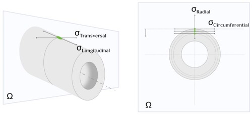
Figure 5. Graphical representation of depth profile of Residual stresses measured by XRD in the circumferential direction.
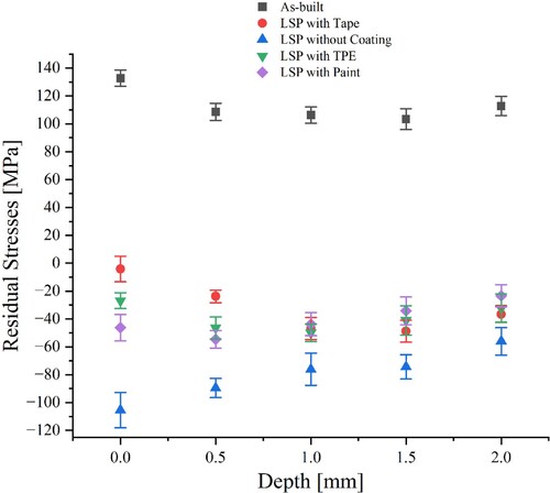
Residual stresses developed in the LSP highly depend on the material of the coatings as can be seen from Equation 1 to 3. To be effective, the sacrificial coating acoustic impedance must be lower than the substrate/sample material, also it must tightly adhere to the substrate surface without wrinkles, bubbles and scratches. If not tightly adhered, overlaying of the sacrificial coating may occur, creating another interface for the shockwave to pass through and losing energy. In other circumstances the coating may get damaged during the LSP processing, thus revealing the sample surface to the laser pulse while also distorting the water flow. Such a situation may lead to inhomogeneity of the processed sample and the effect will be similar to the naked peening as can be seen in Case #2. The risk of tear damage to the coating increases with the higher power density and also with the number of layers used during the LSP processing for which the coating is not reapplied. The application of tape (Case #1) poses a significant risk of overlaying the layers of coating over each other as the flat tape has to be wrapped around the circumference of the sample. For the application of black paint (Case #4), the manufacturer’s recommendation was followed and 4 coats were applied with 30 minutes drying period left between each coat. The paint has the benefit of closely adhering to the complicated geometries, yet the long drying period poses a complication in the industrial setting, specifically when the coating has to be reapplied before the second layer of LSP processing and the sample cannot lose the geometrical reference to the laser and robotic system. Case #3 uses a shrink tube made of thermoplastic elastomer as a sacrificial coating to avoid the risk of overlaying the coating. For such types of geometries, the application is easy, fast, and repeatable and without any need for specific training. Following the above discussion, it can be seen from , that the naked peening (Case #2) resulted in the highest average values of compressive residual stresses (CRS) of – 80 MPa and it also resulted in the deepest penetration in the materials up to 2 mm in compressive regime. Similar trends have been observed when coatings were used with the largest discrepancy being close to the outer surface where Case #2 achieves the largest amount of compression and performs the best, followed by LSP with paint (Case #4), LSP with TPE (Case #3) and LSP with tape (Case #1).
3.2. Analysis of the porosity (defect ratio %)
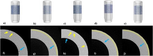
The structure is prone to the formation of porosities due to the meeting of two printing strategies. During the printing process, the skin of the part which has been solidified in the previous step has to bond to the new region which is being solidified (the core of the part). Nonetheless, the newly formed surface might be prone to oxidation to a certain extent due to impurities in the powder itself and in the inert atmosphere during the printing as well as the thermal gradients differing significantly, both serving as a barrier for full consolidation. The solidified structure has much greater thermal capacity as opposed to the metal powder which might lead to temperature differences in the meltpool when constant laser heat input is applied, leading to the formation of porosity. and present the computed tomography (CT) data generated for the unpeened and LSP-processed samples with different sacrificial coatings. depicts the defect ratio in % which can be referred to as the overall computed porosity of the sample before and after LSP processing. It can be seen from that Case #1 i.e. LSP with tape as sacrificial coatings performed the best in the overall reduction of porosity, while Case #4 (LSP with Paint) and Case #2 (LSP without coating) also performed satisfactorily in contrast to case #3 (LSP with TPE). The observed findings can be justified by the fact that the pressure generated in Case #3 of 1320 MPa although greater than the HEL of 3D printed aluminium of 300 MPa combined with the reflection coefficient of 0.93 and the highest thickness of the coating of 0.31 mm resulted in plastic deformation which was sufficient to generate compressive residual stress. Nevertheless, the overall plastic deformation did not reach a sufficient amount to be able to significantly close the pores or reduce their volume under the detection criteria of the tomography setup. Similar findings were also observed while quantifying the electron beam scattered diffraction images, where minimal changes in grain sizes after LSP were observed for Case #3. The details are presented in the next subsections. This phenomenon is further exhibited on the reconstructed image from CT in d where the remaining porosity near the outer surface is highlighted with a yellow arrow. As presented in the porosity of the samples is not evenly distributed. In all other cases (e.g. #1, #2 and #4) the pressure shockwave proved successful in closing or reducing the porosity of the sample mainly nearing the outer edge of the sample as presented in reconstructed images in b, d and e.
Figure 6. Graphical representation of overall porosity reduction. The highest reduction of porosity was achieved with LSP With Tape (from 1.08% to 0.36%), and the least reduction was observed with LSP With TPE (from 0.97% to 0.94%).
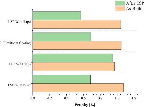
Figure 7. Computed tomography: (a–e) isometric view, (f–j) reconstructed image (section). (a) and (f) before LSP processing; (b) and (g) LSP without coating; (c) and (h) LSP with TPE; (d) and (i) LSP with paint; (e) and (j) LSP with tape. First row: detected porosity is highlighted in blue with base material having increased transparency. Second row: Porosity near the inner ring is highlighted using blue arrows; porosity near the outer ring is highlighted with yellow arrows, the yellow area represents the main area of porosity reduction.
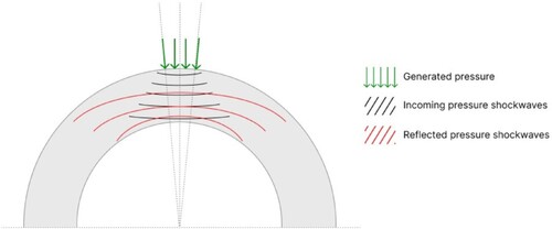
As the shockwave propagates through the structure, it can be reflected from the back surface. In the event of backpropagation, the compression wave usually transforms into a tensile wave and travels within the materials without inducing any beneficial effects. Furthermore, if the magnitude of the reflected wave exceeds the spall strength of the material, the treated component can be damaged at the subsurface level, enlarge the defects or reach complete cracking on the back surface of the component. The data suggest that such adverse effects did not occur in the present study as no cracking or broadening of the defects was observed. The propagation and back reflection of the waves could have been affected by the geometry of the sample as observed by Stránský et al. [Citation24]. The reflected waves could be spread over a substantially larger area effectively lowering their magnitude and preventing the spalling defects from developing as presented in .
Figure 8. Schematic representation of shockwave propagation in the thin cross-section cylindrical component.
3.3 Crystallography, microstructure and microhardness
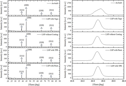
The sample XRD patterns are displayed in . Following LSP treatments, there is no alteration in the primary phases. In all the cases, a notable peak associated with the Al phase can be seen. The crystalline planes show uniformity amongst all the samples. shows the XRD patterns of the samples. The main phases, i.e. α-Al did not change after LSP treatments. A strong peak related to the Al phase is identified in all samples. The preferred orientations of the crystalline planes remain the same. after LSP treatments, the diffraction intensities associated with the Al phase peak across the crystal planes, such as Al (111) and Al (200), increase significantly. The increased intensity of diffraction peaks observed in X-ray diffraction patterns after laser shock peening (LSP) compared to the as-built sample suggests improvements in the material crystalline volume. Furthermore, the lattice strain was also observed after LSP in all four cases with crystallite size ranging between 20 and 45 nm. These improvements could be due to more ordered grain orientation, a refined grain size distribution, higher levels of induced compressive residual stresses or the development of a more pronounced texture within the material.
Figure 9. X-ray diffraction patterns of As-built and LSP processed samples.
presents the electron back-scattered diffraction (EBSD) analysis and grain orientation map for (a) As-built; (b) LSP with tape;(c) LSP without coating; (d) LSP with TPE and (e) LSP with paint. (f–j) shows the grain size distribution map and corresponding histograms for (f) As-built; (g) LSP with tape; (h) LSP without coating; (i) LSP with TPE and (j) LSP with paint. The distribution of average grain sizes is presented in (a). It can be seen by comparing (b–e) to (a) that the LSP processing produces a recrystallised zone at a certain depth. It has a distinct texture, and the grains are extended along the radial direction [see (b–e)]. It can be seen from (a) that all four different experiments exhibited reductions in grain size, which highlights that the peening procedure induces microstructural changes. Average grain size reduction from 6.2 µm to 4.89 µm was seen in the uncoated aluminium substrate, indicating the underlying influence of shockwaves. With the inclusion of coatings, the effects were further influenced as the average grain size of 4.43 µm was observed while using the vinyl tape-coated sample; the black paint-coated sample (average grain size: 4.24 µm) showed a similar pattern, highlighting the impact of shockwave absorption and coating homogeneity on microstructural evolution. In contrast, the sample coated with TPE showed a somewhat bigger average grain size of 5.2 µm. The low refinement in the case of TPE compared to vinyl tape and black paint is due to its larger reflection coefficient and lower predicted peak pressure, which affects the shockwave dynamics created by the TPE sacrificial coating. The shockwave and acoustic characteristics of sacrificial coatings are crucial in determining microstructural alterations [Citation32]. The thermoplastic elastomers’ lower shock impedance and lower peak pressure may have an impact on shockwave transmission within the workpiece material. Together with lower reflection coefficients, the greater predicted peak pressure in the vinyl tape and black paint-coated samples suggests improved shockwave absorption. Due to this fact, the sample coated with vinyl tape and black paint demonstrated enhanced microstructural changes, which are probably a result of this absorption.
Figure 10. Electron backscattered diffraction analysis, IPF for (a) As-built; (b) LSP with tape;(c) LSP with and without coating; (d) LSP with TPE; and (e) LSP with paint. (f–j) grain size distribution map for (f) As-built; (g) LSP with tape;(h) LSP without coating; (i) LSP with TPE; and (j) LSP with paint.
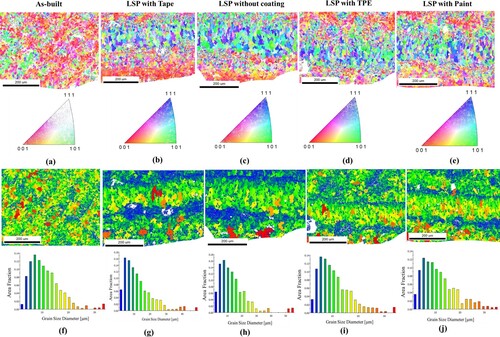
Figure 11. Graphical representation of (a) grain size distribution; and (b) misorientation angle with respect to number fraction.

demonstrates the kernel average misorientation (KAM) plots of the as-built samples (a) and LSP processed samples [(b–e)]. KAM is a useful tool for evaluating the dislocation build-up and lattice deformation. Increased stored energy within the structure is indicated by elevated KAM values. A higher deformation is visible in the as-built sample, as shown in (a), a higher deformation in LPBF-produced sample indicates that the materials undergoing significant thermal cycling and solidification. Furthermore, (b–e) depicts the KAM plots for LSP-processed samples and it can be noticed that controlled plastic deformation leads to dislocation rearrangement and grain refinement (as discussed in ). Also, (b) shows the details extracted from the kernel misorientation maps, where the kernel values are presented with the change in respective angles in degrees. It can be observed from (b) that up to the 1 degree the misorientation values are higher in all 4 cases which may result from more prominent local deformation caused by LSP at lower misorientation angles. The localised deformation decreases with an increase in measuring angle which in turn results in lower KAM values. At grain boundaries, high misorientations are due to the extreme plastic deformation by LSP. The misoriented grains may realign because of additional deformation or stress-relief mechanisms, which lowers the total misorientation values at higher angles.
Figure 12. Kernel orientation map for (a) As-built; (b) LSP with tape;(c) LSP without coating; (d) LSP with TPE and (e) LSP with paint. (f–j) grain boundary distribution map for (f) As-built; (g) LSP with tape;(h) LSP without coating; (i) LSP with TPE and (j) LSP with paint. Similarly, Figure 12(k–o) represents the grain angle boundary distribution for (k) As-built; (l) LSP with tape;(m) LSP without coating; (n) LSP with TPE and (o) LSP with paint.
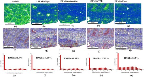
It can also be noticed by comparing (f) to (g–j) that plastic deformation served by LSP has altered the grain boundaries and high-angle grain boundaries (HAGBs) are transformed into low-angle grain boundaries (LAGBs) and vice versa, the transformation of LAGBs to HAGBs is more prominent while using LSP without coatings and with black vinyl paint where the HAGBs percentage increased from 45.5% to 48.3% and 55.7%, respectively. This migration of LAGBs to HAGBs is primarily due to the direct interaction of laser pulse with the material in the case of LSP without coating. Whereas, LSP with black paint as sacrificial coating provides excellent adherence and a uniform layer over the surface which eliminates the risk of tearing off or dislodgement of the sacrificial coating. This facilitates the continuous energy absorption and transmission of shockwaves within the material and results in severe mechanical effects within the material. The HAGBs transformed to LAGBs when using black vinyl tape and thermoplastic elastomers as sacrificial coatings where the LAGBs percentage increased from 54.5% (as-built) to 58.3% (LSP with tape) and 62% (LSP with TPE) suggests that there was some degree of microstructural rearrangement and plastic deformation throughout the LSP process although referencing to the magnitude of the compressive residual stresses (as presented in ), the intensity of the plastic deformation seems less in both the cases due to several factors such as the thickness of the tape and TPE coating, efficiency of absorption of energy and shockwave transmission.
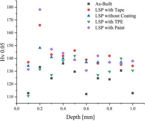
presents the details of measured Vicker's microhardness Hv 0.05 for all the samples. It can be observed from that a marginal improvement in the microhardness values was observed across all the LSP processed samples, irrespective of the sacrificial coatings used. The average hardness increase of LSP-processed samples is 11.7% compared to the As-built state. The highest increase of 14.5% and 14.8% was observed in cases #2 and #3 where the tape and paint were used, respectively. The lowest increase of 5.4% on average was observed in case #4, with case #1 falling in between with 12%. The changes in hardness were attributed to the refinement of microstructure (), the creation of new grain boundaries and increased dislocation density serving as barriers for dislocation movement.
Figure 13. Vickers microhardness Hv 0.05 profile for the depth of 1 mm.
3.4. Analysis of surface properties
The surface finish is an important functional property of the part. It is affecting the usability of the part in tribological performance. Traditionally when assessing the surface finish, the extracted profile contains surface roughness, waviness and form and these are separated by filtration. The profile is regarded as a wave and through frequency separation, roughness and waviness are separated. In conventional machining the roughness can be correlated to cutting conditions and waviness to the rigidity of the setup (tool-machine-workpiece); however, these correlations become problematic in technologies such as LSP where no such distinction can be made. The shortest frequencies, assessed with the average surface roughness Ra are compared in a. The roughness after the LSP processing has not increased drastically in cases #1, #3 and #4 i.e. the cases where the sacrificial coating prevented the direct interaction of the laser pulse with the treated material as opposed to case #2 of LSP without coating where the ablation and thermal effect remained prevalent. The change in longer frequencies (waviness) has been observed much greater than the change in roughness, as presented in b. The lowest increase occurred in case #3, where TPE was used as a sacrificial coating, which is explained by the least amount of plastic deformation as compared to other cases. The plastic deformation of a single laser pulse is in the area of the circle with 1.15 mm diameter and when is the surface protected from the direct laser-matter interactions, it does not greatly affect the shortest frequencies belonging to the roughness parameters but increases the longer frequencies of waviness. Furthermore, the volumetric parameters, such as peak material volume Vmp, core material volume Vmc, dale material volume Vvv and core dale volume Vvc, have been studied with the help of material ratio curves obtained before and after LSP to study the effects of different sacrificial layers on material properties. depicts the material ratio curve and corresponding values of Vmp, Vmc, Vvv and Vvc before and after LSP processing. It can be noticed from and the values presented in , that peak material volume has been reduced after LSP treatment with TPE and paint as a sacrificial layer, which can be attributed to the plastic deformation reducing the height of the peaks. In the case of LSP without coating, the effects of direct interaction between the laser pulse and the surface of the part became more prevalent and the overall roughness as well as all the volume functional parameters increased resulting in increased height of the material curve. The case of LSP with TPE displays the least amount of surface properties alterations, followed by LSP with paint and tape which are performing similarly to each other. Furthermore, the increase in the values of Vmc, Vvv and Vvc affirms in all the cases that the core and void volume have been altered by the LSP processing and material density and void have shifted.
Figure 14. Comparison of surface finish before and after LSP processing: (a) Average Surface Roughness Ra and (b) Average Waviness Wa.
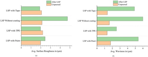
Figure 15. Material ratio curves for all the experiments before and after LSP treatment.
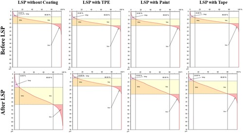
Table 2. Numerical data of the material ratio curves for all the experiments before and after LSP treatment.
Conclusions
This research suggests that sacrificial coatings play an important role in processing parts in laser shock peening. The impacts of different coatings in LSP on surface residual stresses, depth profile of residual stresses, porosity, microstructure, micro-hardness and surface quality parameters such as roughness and material ratio curves were experimentally investigated. The following inferences can be reached based on the current experimental work:
The highest average values of compressive residual stresses (CRS) – 80 MPa were observed in naked peening due to the direct and prominent interaction of laser pulses with the material. The rest of the experimental conditions i.e. LSP with tape, LSP with paint and LSP with thermoplastic elastomers were also able to shift the residual stress regime from tensile to compressive but not to such an extent.
The porosity was best improved while peening the sample using tape and paint as a sacrificial coating due to their better adhesion to the sample. Whereas marginal improvement was observed in the case of LSP with thermoplastic elastomers and without coating.
Average surface roughness has increased by over 50% while peening without coating mainly due to direct ablation, whereas for other cases such as LSP with tape and thermoplastic elastomers the Ra values have shown marginal improvement, which shows that the coatings protect or safeguard the base material from the ablative or thermal effects in laser shock peening.
The microstructure analysis has shown that L-PBF manufactured AlSi10Mg thin tubes undergo distinct crystallographic alterations during LSP; increased microstructural variations were observed in sacrificial coatings such as black vinyl tape and black paint. Grain refinement and formation of sub-grains were observed in all the samples irrespective of coating material. These results highlight the complex effects on crystallography in additively made components of shockwave dynamics and coating choice.
The Vickers microhardness has also shown marginal improvement for all the samples, particularly due to plastic deformation and grain refinement.
The choice of the optimal sacrificial coating is contingent upon the specific application requirements as various coatings significantly influence both surface integrity and the overall effectiveness of the LSP process. When disregarding roughness increase and prioritising cost may lead to satisfactory performance in uncoated LSP, an alternative perspective shall be considered when surface roughness becomes critical for the intended use of the treated part, and time constraints are less pressing. In such cases, employing LSP with a paint coating is recommended as this configuration consistently yields superior results, coupled with the advantage of enhanced adherence of the coating to the treated surface.
Acknowledgements
The authors would like to acknowledge the help of Inam Mirza, Ph.D. with XRD diffraction pattern measurement.
Disclosure statement
No potential conflict of interest was reported by the authors.
Data availability statement
The authors confirm that the data supporting the findings of this study are available within the article [and/or] its supplementary materials.
Additional information
Funding
References
- Zulić S, Rostohar D, Kaufman J, et al. Fatigue life enhancement of additive manufactured 316 l stainless steel by LSP using a DPSS laser system. Surf Eng. 2022;38(2):183–190. doi:10.1080/02670844.2022.2060463
- Peyre P, Fabbro R, Berthe L, et al. Laser-shock processing of materials and related measurements. In: Proceedings of SPIE – The International Society for Optical Engineering. Santa Fe, NM, USA; 1998. Volume 3343, p. 183–193. doi:10.1117/12.321565
- Peyre P, Sollier A, Chaieb I, et al. FEM simulation of residual stresses induced by laser peening. Eur Phys J Appl Phys. 2003;23(2):83–88. doi:10.1051/epjap:2003037
- Peyre P, Scherpereel X, Berthe L, et al. Surface modifications induced in 316L steel by laser peening and shot-peening. influence on pitting corrosion resistance. Mater Sci Eng A. 2000;280(2):294–302. doi:10.1016/S0921-5093(99)00698-X
- Berthe L, Fabbro R, Peyre P, et al. Wavelength dependent of laser shock-wave generation in the water-confinement regime. J Appl Phys. 1999;85(11):7552–7555. doi:10.1063/1.370553
- Dhakal B, Swaroop S. Review: laser shock peening as post welding treatment technique. J Manuf Process. 2018;32:721–733. doi:10.1016/j.jmapro.2018.04.006
- Fox JA. Effect of water and paint coatings on laser-irradiated targets. Appl Phys Lett. 1974;24(10):461–464. doi:10.1063/1.1655012
- Sano Y, Akita K, Sano T. A mechanism for inducing compressive residual stresses on a surface by laser peening without coating. Metals. 2020;10(6):816. doi:10.3390/met10060816
- Karthik D, Kalainathan S, Swaroop S. Surface modification of 17-4 PH stainless steel by laser peening without protective coating process. Surf Coat Technol. 2015;278:138–145. doi:10.1016/j.surfcoat.2015.08.012
- Kaufman J, Racek J, Cieslar M, et al. The effect of laser shock peening with and without protective coating on intergranular corrosion of sensitized AA5083. Corros Sci. 2022;194. doi:10.1016/j.corsci.2021.109925
- Pathak S, Zulić S, Kaufman J, et al. Post-processing of selective laser melting manufactured SS-304L by laser shock peening. J Mater Res Technol. 2022;19:4787–4792. doi:10.1016/j.jmrt.2022.07.014
- Sundar R, Kumar H, Kaul R, et al. Studies on laser peening using different sacrificial coatings. Surf Eng. 2012;28(8):564–568. doi:10.1179/1743294412Y.0000000029
- Yella P, Venkateswarlu P, Buddu RK, et al. Role of sacrificial layers on surface characteristics of laser shock peened SS304 plates. Opt Laser Technol. 2018;107:142–149. doi:10.1016/j.optlastec.2018.05.018
- Sanchez AG, Leering M, Glaser D, et al. Effects of ablative and non-ablative laser shock peening on AA7075-T651 corrosion and fatigue performance. Mater Sci Technol. 2021;37(12):1015–1034. doi:10.1080/02670836.2021.1972272
- Laurençon M, de Rességuier T, Loison D, et al. Effects of additive manufacturing on the dynamic response of AlSi10Mg to laser shock loading. Mater Sci Eng A. 2019;748:407–417. doi:10.1016/j.msea.2019.02.001
- Pavan M, Furfari D, Ahmad B, et al. Fatigue crack growth in a laser shock peened residual stress field. Int J Fatigue. 2019;123:157–167. doi:10.1016/j.ijfatigue.2019.01.020
- Dhakal B, Swaroop S. Effect of laser shock peening on mechanical and microstructural aspects of 6061-T6 aluminum alloy. J Mater Process Technol. 2020;282:116640. doi:10.1016/j.jmatprotec.2020.116640
- Kalentics N, Huang K, Ortega Varela de Seijas M, et al. Laser shock peening: a promising tool for tailoring metallic microstructures in selective laser melting. J Mater Process Technol. 2019;266:612–618. doi:10.1016/j.jmatprotec.2018.11.024
- Wu Z, Wu S, Duan Y, et al. In situ X-ray tomography of fracture behaviour in low-porosity L-PBF AlSi10Mg alloy with laser shock peening. Virtual Phys Prototyp. 2023;18(1):e2273955. doi:10.1080/17452759.2023.2273955
- Zhou J, Sun Y, Huang S, et al. Effect of laser peening on friction and wear behavior of medical Ti6Al4 V alloy. Opt Laser Technol. 2019;109:263–269. doi:10.1016/j.optlastec.2018.08.005
- Ye C, Zhang C, Zhao J, et al. Effects of post-processing on the surface finish, porosity, residual stresses, and fatigue performance of additive manufactured metals: a review. J Mater Eng Perform. 2021;30(9):6407–6425. doi:10.1007/s11665-021-06021-7
- Clauer AH. Laser shock peening, the path to production. Metals. 2019;9(6):626. doi:10.3390/met9060626
- Wu Z, Wu S, Qian W, et al. Structural integrity issues of additively manufactured railway components: progress and challenges. Eng Fail Anal. 2023;149; doi:10.1016/j.engfailanal.2023.107265
- Stránský O, Beránek L, Pathak S, et al. Porosity and microstructure of L-PBF printed AlSi10Mg thin tubes in laser shock peening. J Mater Res Technol. 2023;27:1683–1695. doi:10.1016/j.jmrt.2023.10.013
- Bovid S, Kattoura M, Clauer A, et al. Pressure amplification and modelization in laser shock peening of Ti-6Al-4 V and AA7085 with adhesive-backed opaque overlays. J Mater Process Technol. 2022;299:117381. doi:10.1016/j.jmatprotec.2021.117381
- Wang X, Xia W, Wu X, et al. Scaling law in laser-induced shock effects of NiTi shape memory alloy. Metals. 2018;8(3):174. doi:10.3390/met8030174
- Fang W, Fei Y, Lu H, et al. Enhanced sound insulation and mechanical properties based on inorganic fillers/thermoplastic elastomer composites. J Thermoplast Compos Mater. 2018;32(7):936–950. doi:10.1177/0892705718766382
- Peyre P, Fabbro R, Merrien P, et al. Laser shock processing of aluminium alloys. Application to high cycle fatigue behaviour. Mater Sci Eng A. 1996;210(1-2):102–113. doi:10.1016/0921-5093(95)10084-9
- Pathak S, Böhm M, Kaufman J, et al. Microstructure and surface quality of SLM printed miniature helical gear in LSPwC. Surf Eng. 2023;39(2):229–237. doi:10.1080/02670844.2023.2207934
- Zou S, Wu J, Cao Z, et al. Numerical analysis of mechanical effects of laser shock peening. In: Laser shock peening. Singapore: Springer; 2023;87–124. doi:10.1007/978-981-99-1117-2_4
- Jarmakani H, Maddox B, Wei CT, et al. Laser shock-induced spalling and fragmentation in vanadium. Acta Mater. 2010;58(14):4604–4628. doi:10.1016/j.actamat.2010.04.027
- Tollier L, Fabbro R, Bartnicki E. Study of the laser-driven spallation process by the velocity interferometer system for any reflector interferometry technique. I. Laser-shock characterization. J Appl Phys. 1998;83(3):1224–1230. doi:10.1063/1.366819
- Fabbro R, Peyre P, Berthe L, et al. Physics and applications of laser-shock processing. J Laser Appl. 1998;10:265–279. doi:10.2351/1.521861