
 ?Mathematical formulae have been encoded as MathML and are displayed in this HTML version using MathJax in order to improve their display. Uncheck the box to turn MathJax off. This feature requires Javascript. Click on a formula to zoom.
ABSTRACT
The increasingly distressing problem of noise pollution prompts the rapid research and development of lattice-based acoustic materials for practical applications. These lattices boast excellent mechanical properties and unlimited design freedom made possible using additive manufacturing technologies. Currently, there is a lack of analytical mathematical models relating the lattice geometry to the acoustic models and the absence of software dedicated to the acoustic modelling of strut lattice-based sound absorbers. This work presents LattSAC, an acoustics calculator that takes in all the geometrical parameters of the lattice structure and outputs directly the sound absorption coefficients (SAC) and their statistics. Hidden within the code is the novel Multi-layered Micropore-Cavity (MMC) model with semi-empirical mathematical models well-trained using experimental data to output the SACs with excellent accuracies. This software aims to accelerate the research and development of lattice-based acoustic absorbers for actual applications. It also functions as a valuable tool for users looking to design sound-absorbing materials using lattice structures. The software installer may be downloaded for free from the following GitHub repository: https://github.com/JunWeiChua/LattSAC. If there are any suggestions or contributions, the user may write to [email protected].
Highlights
LattSAC, a lattice acoustics modelling software was developed.
LattSAC outputs sound absorption coefficients using only lattice geometrical data.
LattSAC implements high-fidelity numerical acoustics models.
Mean absolute errors for the predictions are extremely low at about 0.053.
Software capable of modelling lattices with heterogeneous assembly of unit cells.
1. Introduction
Noise is a staple of urban living in modern cities, with many sources of unwanted, unpleasant sounds such as land and air transportation, construction, and industrial machinery [Citation1]. Within recent decades, the increasing speed of urban development worldwide caused the problem of noise pollution to be more severe and deserves significant attention [Citation2]. When poorly managed, exposure to urban noise leads to several physical, mental, and economic consequences, including but not limited to irreversible hearing loss, sleep disturbances, increased stress, and anxiety [Citation3], and decreased economic productivity [Citation4]. To cope with the increasingly severe problem of noise pollution, a vast range of sound-absorption and insulation materials have been developed by acoustics researchers and engineers, such as cellular foams [Citation5], fibrous materials [Citation6,Citation7], aerogels [Citation8,Citation9], lattice structures [Citation10–12], microperforated panels [Citation13–15] and acoustic metamaterials [Citation16–19].
Within the past decade, there has been an increasing interest in the research of lattice-based acoustic materials for practical applications [Citation20]. These entities manifest as periodically recurring 3D structured unit cells, characterised by components like struts, plates, or voids, exhibiting dimensions within the micrometer scale [Citation21]. Some of the advantages of lattice structures observed were being lightweight, high specific energy absorption, large surface areas per unit volume, large design freedoms, and potential for use in a large range of applications [Citation20,Citation21]. Three of the major categories of lattices are strut lattices, plate lattices, and triply periodic minimal surface (TPMS) lattices. Strut lattices are based on determined spatial arrangements of struts in three-dimensional space [Citation22]. Plate lattices, on the other hand, feature a collection of thin plates instead of struts arranged in pre-defined positions within the unit cell. TPMS lattices are created based on parametric equations and may take on either the surface form or the skeletal bounding volume form. There exist many prior works on this topic, such as on structures mimicking material crystal structures [Citation10], triply periodic minimal surface (TPMS) structures [Citation12], spherical cavities [Citation23], and Kelvin-cell [Citation11] microlattices. In the realm of lattice structures, strut lattices stand out as superior sound absorbers due to their remarkable customisability, showcasing exceptional potential for both high and broadband absorption capabilities [Citation10,Citation24,Citation25].
The acoustic properties of strut lattice structures can be modelled using popular mathematical models such as the models proposed by Delany and Bazley (DB) [Citation26], Johnson et al. [Citation27,Citation28], and Biot [Citation29], with the aid of analytical and finite element methods. Notable works that adopted this approach are the works by Boulvert et al. [Citation24,Citation30] for lattices with interwoven perpendicular arrangements and Rice et al. [Citation11] for Kelvin-cell lattices. A common characteristic of the models is the representation of the overall lattice materials as equivalent fluid medium with several non-acoustic parameters. More recently, a series of studies by Li et al. [Citation10,Citation25] suggest that some lattice designs may be modelled using the theory of Helmholtz resonators and microperforated panels [Citation31,Citation32]. These are structures that consist of large enclosed volumes of air cavities that are connected to the rest of the outside environment by narrow perforations. An advantage over the previous models is the ability to model lattice structures comprising heterogeneous layers. It was notable that the use of the theory of microperforated panels in the works requires the use of end-correction factors which are highly dependent on the lattice geometry and needs to be determined on a case-by-case basis through experimentation or numerical simulations. However, a major drawback of both approaches is the lack of research on analytical mathematical models that directly relate the geometrical parameters of the lattice absorbers and insulators to the parameters in the respective acoustic models. Thus far, prior works on such analytical approaches such as those from Doutres et al. [Citation33,Citation34] and Zhai et al. [Citation35–37], focus on the geometrical parameters of foams and aerogels. While the geometrical parameters of lattice structures tend to be deterministic with few signs of randomness, there are still very few mathematical models that relate their geometry to the acoustic model parameters.
Moreover, a major advantage of strut lattices as acoustic materials is the large design freedom concerning the unit cell geometry and methods of repetitions. That being said, it is not possible that the relations between the geometry of the lattices and the parameters of the acoustic models can be represented accurately with a single mathematical model. For this problem, there is a need for a suitable medium that can contain a large number of possible mathematical models and apply the suitable models for each instance. It is noted that there are already a significant number of prominent computer programs and applications that can generate lattice structures, such as FLatt Pack [Citation38], Lattice_Karak [Citation39], and MSLattice [Citation40]. These programs have the capability of generating lattice structures of various geometries and with various pre-defined mechanical properties. However, as of present, there is still no such program or software that is dedicated to the design or modelling of the acoustic properties of lattice structures, especially those with heterogeneous geometries.
This work presents LattSAC, a lattice design and modelling application that designs various lattice sound-absorbing materials by inputting only the necessary geometry parameters. The software then calculates the sound absorption coefficients (SAC) of the lattice sound absorber with insights into the mean performances over selected frequency bands. The lattice design, as well as the SAC plots and statistics, may be exported into separate files for future reference. An implementation based on seven different strut lattice unit cell designs was presented in this article, such as the process of building the heterogeneous lattice sound absorbers from the basic building blocks and the construction of semi-empirical mathematical models that determine relations between the lattice geometries to the acoustic models, including the determination of the model correction factors. This software aims to facilitate fast, easy, and effective lattice sound absorber design for engineers and researchers who fabricate sound absorbers for practical applications.
2. Materials and methods
2.1. Lattice modelling approach
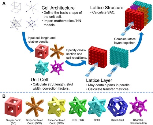
The workflow for the construction of a lattice sound absorber is shown in A. The process starts by identifying the cell architectures that the desired lattice sound absorber may contain. At the time of writing, the software contains seven unit-cell architectures based on strut lattices as shown in B. These unit cells were highly representative of the vast number of research on the mechanical or functional properties of strut lattices in the scientific literature [Citation10,Citation11,Citation41–43]. For each cell architecture, an object was created within the software which contains the necessary information that defines the design, such as the name, number of struts and nodes, and maximum and minimum degrees of the vertices. The object also contains the necessary mathematical models required to calculate the strut length, strut width, and the model correction factors once the unit cell is initialised. In the software itself, the unit cells may be initialised by inputting the cell size and relative density (RD), which is the volume of strut material divided by the total bulk volume occupied by the cell. The strut lengths and widths, as well as model correction factors, were calculated using the mathematical models at this point. Thereafter, the lattice layers were built from the unit cells by specifying the lattice cross-section and number of repetitions in the three directions in the cartesian plane. Each layer of the lattice may contain more than one distinct lattice part, each with a defined surface ratio, which is the area ratio occupied by each part as seen through the lattice cross-section. Finally, the lattice layers were assembled into a single lattice structure, and the acoustic properties such as the SAC may be calculated.
Figure 1. (A) The workflow for the construction of a heterogeneous lattice sound absorber in LattSAC. (B) The lattice unit cell architectures are included in the LattSAC application.
2.2. Mathematical modelling of acoustic properties
In this work, the acoustic properties of the strut lattices were represented mathematically by a model that combines the principles of Helmholtz resonators and the Transfer Matrix Method (TMM). This model was named herein as the Multi-layered Micropore-Cavity (MMC) model and was used in previous studies with good accuracy [Citation44]. The basic idea of a Helmholtz resonator is the use of a bottleneck-like geometry comprising of a narrow neck connected to a large, enclosed cavity to enhance the sound absorption and transmission loss within a narrow, targeted frequency range (A(i)). In a visual sense, the struts that are on the same plane can be seen as a neck of the Helmholtz resonator while the air pockets that the strut encloses bear some resemblances to the cavities. The TMM is a mathematical tool that relates the acoustic pressure and velocity between multiple heterogeneous layers by representing each layer by a transfer matrix [Citation45]. Consider a layer of acoustic material with length , wave number
and characteristic acoustic impedance
, as shown in A(ii). By assuming that the acoustic waves propagating within the layer are plane waves, the acoustic pressure and velocity within the layer can be represented by the following relations:
(1)
(1)
(2)
(2) where
and
are the amplitudes of the two waves. The TMM relates the pressure and velocities at the two ends of the layer (
and
) by the following relation [Citation45]:
(3)
(3) Unlike the DB and JCA models which represent the strut lattices as homogeneous porous materials, the MMC model views the lattices in the form of multiple sequential Helmholtz resonators. To use the model, a representation of the air domain within the strut lattices is required. Considering the truss arrangements of strut lattices, the sub-domains of all structures consist of an open cavity with two narrow tubes of square cross-section at the front and back, as shown schematically in B. As a fundamental and representative unit, the morphology of the air domain within the SC-Truss unit cell serves as the basis for all strut lattices. The narrow tubes have a side length of
and a thickness of
. The air cavity is modelled as a layer of air of thickness
. Here, we define the SC-equivalent strut lengths
and radii
for each unit cell as follows:
(4)
(4)
(5)
(5) where
and
are experimentally determined correction factors that are applied to each unit cell. For the SC-Truss unit cell, it may be taken by
without significant losses in modelling accuracy.
Figure 2. (A)(i) Schematic of a typical Helmholtz resonator. (ii) Schematic of an acoustic material characterised by the transfer matrix [Citation45]. (B) Modelling of the air domain of the strut lattices for the MMC model. (C) Schematic of the regression neural network model to train the
correction factor for the MMC model.
![Figure 2. (A)(i) Schematic of a typical Helmholtz resonator. (ii) Schematic of an acoustic material characterised by the transfer matrix T [Citation45]. (B) Modelling of the air domain of the strut lattices for the MMC model. (C) Schematic of the regression neural network model to train the δ correction factor for the MMC model.](/cms/asset/5ae82527-1d3f-494c-bee5-353dac533af5/nvpp_a_2342432_f0002_oc.jpg)
Based on the works by Maa, Morse, and Ingard [Citation32,Citation46] on acoustic absorbers based on microperforated panels, the characteristic impedance of the square tubes can be expressed as follows:
(6)
(6) where
and
are the dynamic viscosity and density of air respectively,
is the angular frequency of the incoming acoustic waves,
is the imaginary unit such that
.
is the perforation ratio of the lattice, given by
.
refers to the perforate constant, and
refers to the resistive end-correction factor that accounts for the air friction arising from the oscillatory viscous flow on the surface of the perforated panel. Here,
and
are the resistive and reactive correction factors to be determined from experimentally determined SAC results from this work. Thereafter, the transfer matrix for the square tubes is given by [Citation45]
(7)
(7) Furthermore, by representing the open cavity as a layer of air of density
and speed of sound
, the transfer matrix of the cavity
is given by [Citation45]
(8)
(8) where
is the characteristic impedance and
is the wave number of the air layer. Finally, the transfer matrix of one layer of SC-Truss unit cells is given by
(9)
(9) Often in this work, there were cases in which two or more distinct lattice components may be placed in parallel. In such cases, the transfer matrices of each component
are transformed into their admittance matrices,
[Citation47]:
(10)
(10) with
(11)
(11) The overall transfer matrix for the layer,
, was calculated using the terms of admittance matrices as follows:
(12)
(12) where
is the area fraction of the
component for the particular layer
.
Lastly, the TMM was used to account for the acoustic properties of heterogeneous layers in series. The general expression for the transfer matrix of the heterogeneous lattice
was based on the following expression:
(13)
(13) where
is the transfer matrix representation of the
layer. The SAC of the lattice
may be obtained using the elements of
as follows:
(14)
(14) For each unit cell, a parameter study was conducted with the cell sizes and RDs varied according to the values given in . All permutations of unit cells, cell sizes, and RDs were considered for the training of the MMC model, with the sample height and diameter fixed at 30 and 24 mm respectively. For every experiment case, the optimum correction factors
,
,
and
were obtained using the MMC model and experimental data. Thereafter, empirical relations between the lattice geometrical parameters (cell size and RD) and the correction factors
and
were obtained using curve fitting to power-law mathematical models and regression machine learning models respectively (C). For each unit cell, the mathematical model for
takes the form
, where
are constants unique for each unit cell. In the regression neural network, a third input
was added. This addition of feature takes inspiration from the circular backpropagation (CBP) network, which was shown to have comparable performance to conventional multilayer perceptron neural network models when used in some classification and regression problems [Citation48,Citation49]. The network itself contains one input layer, one output layer, and two hidden layers. The activation functions and the number of hidden neurons in each layer were determined using the in-built hyperparameter optimisation argument within the fitrnet function in MATLAB.
Table 1. Values of geometrical parameters for the lattice sample used in the training of the MMC model.
A model validation study was then conducted with four randomly generated heterogeneous lattice samples with distinct layers and parts arranged in series or parallel. The details of the geometry of the four heterogeneous lattices are appended in Table S1 in the Supplementary Information. It was noted that plate partitions were introduced wherever there were lattice parts arranged in parallel in the sample lattice layer to separate the respective air domains. This was done due to an important assumption in Equations (7) to (9) requiring the acoustic wave to not cross between adjacent lattice parts.
2.3. Fabrication of strut lattices
For all permutations of unit cells, cell sizes, and RDs, cylindrical samples of diameter 30 mm and height 24 mm were modelled virtually using SolidWorks software. The geometries were exported to a slicing software and sent to the Voxelab Proxima 6.0 printer for fabrication using vat photopolymerization. The photopolymer resin used for the lattices was the transparent 405 nm resin from NOVA3D, which provides high transparency and high toughness and strength on curing. The thickness of each layer was set at 0.05 mm and the exposure time for each layer was set at 2.1 s. These were determined based on preliminary material testing using the selected printer and resin to obtain optimal print quality. The printed samples were then thoroughly cleaned using isopropyl alcohol and post-cured under UV light for about half an hour. Images of the manufactured samples for the four heterogeneous samples are appended in Figure S1 in the Supplementary Information.
2.4. Acoustic performance characterisation
The SAC of the printed lattice samples was measured experimentally using the BSWA SW477 impedance tube. The standard used for the calculation of SACs was the ISO-10534-2 standard and was programmed into the data acquisition software provided by the supplier. The sample holder has a hole size of 30 mm and the samples were fully inserted into the holder with minimal air gaps at the walls of the holder. The frequency range of interest is between 1000 and 6300 Hz. For each sample, about four sets of SAC measurements were made and then averaged.
3. Results and discussions
3.1. Modeling of lattice sound absorption properties
A shows the experimentally determined SAC plots for selected training lattice samples with the unit cells, RDs, and cell sizes varied according to the values in . A(i) reveals the different SAC distributions of the seven different unit cells. Even with the same cell size and RD, the choice of unit cell architecture has an impact on SACs and hence may be changed according to user specifications. A(ii) and (iii) demonstrate how relative density and cell size influence the SAC of unit cells, using the octet unit cell as an example. Based on A(ii) and (iii), the SACs of strut lattices generally increase with increasing cell size or increasing RDs. This trend relates to the increased acoustic impedance matching of MMC resonators with increasing cell size or increasing RDs in the frequency range of interest. On a side note, the trend is also similar to that of porous foams such that the SACs were enhanced through the use of smaller pore sizes [Citation50]. This knowledge allows one to better tune the SACs of homogeneous lattices by varying the cell size and RDs.
Figure 3. (A) Sound absorption coefficients (SACs) for selected training samples obtained from experimental measurements: (i) Samples with a cell size of 6 mm and relative density (RD) 30%; (ii) Octet samples with RD of 30% and varied cell sizes; (iii) Octet samples with a cell size of 6 mm and varied RDs. (B)(i) SACs obtained from both experiments and the MMC model for the octet strut lattice with a cell size of 6 mm and RD of 30%. (ii-iii) Histogram of the mean absolute errors of all the test cases using the MMC model with correction factors (ii) optimised based on experimental data and (iii) calculated from the regression models. (C) SACs obtained from both experiments and the MMC model for Validation Sample 3 oriented: (i) as designed; (ii) in the reverse direction. (iii) Histogram of the mean absolute errors of all the heterogeneous validation cases using the MMC model.
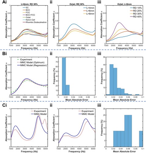
It was found that the approach outlined in Section 2.1.2 was feasible in modeling the sound absorption performances of the homogeneous strut lattices with reasonable accuracy. B(i) shows the SAC plots obtained from both experiments and the MMC Model for a homogeneous lattice sample comprising octet unit cells of length 6 mm and RD of 30%. The plots for the rest of the homogeneous lattice samples in this work were appended in a folder in the Supplementary Information. From the plot, it was found that the SACs of homogeneous lattice structures obtained by both experimental and numerical means were close to one another. Furthermore, the regression and neural network models were trained to obtain the correction factors with relatively good performances, with overall mean absolute errors being slightly larger than when the optimum correction factors were used in the MMC model (B (ii) and (iii)). A reason for the good agreement could be the use of appropriate regression models for the prediction of strut widths and the correction factor . In this work, the strut width of a unit cell was determined as a linear function of cell size and a nonlinear function of RD. Such a modelling approach was reasonable as the cell size mainly determines the magnitude by which a unit cell of length 1 mm is scaled uniformly, while the RD determines the strut widths of the unit cell of length 1 mm. Hence, the strut width for a unit cell of length 1 mm was determined to be a function of RD only, making the mathematical model easy to implement.
C(i) and (ii) show the SACs of a particular validation sample obtained through both experimental measurements and the MMC model. C(i) shows the SACs for the sample when oriented as designed and C(ii) shows the SACs for the same sample when oriented in the opposite direction. The SAC plots for all the validation lattice samples were appended in Table S2 in the Supplementary Information. It was shown that the SAC distributions from both experiments and the MMC model were close to each other. Moreover, because the lattice layers were distinct with different cell sizes and RDs, some variations in SAC were observed when the orientation of the sample was changed. It was noted that the first layer contains a part with an RD of 15% and the third layer contains a part with an RD of 10%. Note from C(i) and (ii) that the SACs at lower frequencies were generally higher for the first sample with the layer of higher RD facing the sound source. This observation could be exploited similarly to functionally graded foams [Citation50], such that the SAC at lower frequencies could be slightly boosted by introducing layers of higher RDs and smaller pore sizes. Based on the histogram of absolute errors in C(iii), the mean absolute error was about 0.053 with none of the errors exceeding 0.1. It is important to note that for some validation cases such as the one in C(i), there exist additional absorption peaks that the MMC model did not capture. These typically occur at high frequencies and may be attributed to the presence of non-planar acoustic modes of wave propagation within the impedance tubes [Citation51,Citation52]. In a circular duct of diameter such as an impedance tube, the cut-on frequency, which is a frequency above which higher-order modes of wave propagation occur, is given by
, where
is the speed of sound in air [Citation53]. For the BSWA SW477 impedance tube of diameter 30 mm,
is about 6700 Hz. This explains the choice of the upper limit of the frequency range that can be plotted in the LattSAC software, which is 6300 Hz. The dispersive nature of hiher-order modes of propagation may result in an increased sound attenuation at high frequencies, such as the additional peak observed in C(i). Overall, the performance of the MMC model in predicting the SAC of heterogeneous lattice sound absorbers was exceptionally good and comparable to that of homogeneous lattice sound absorber samples at frequencies below the cut-on frequency. At frequencies higher than the cut-on frequency, estimations of the acoustic properties of the lattices will be considered as extrapolation and are not validated by experimental results. In such cases, one may choose to supplement the estimations from this application with numerical simulations such as those done using COMSOL Multiphysics Thermoviscous Acoustics module.
3.2. The LattSAC application
A shows the graphical user interface of the LattSAC application. The application was built using the MATLAB App Designer, which is an application within MATLAB that allows one to create professional-looking applications with minimal programming or software engineering experience. The graphical user interface (GUI) was created by using various visual components within the component library and then programming the user behaviour using the built-in code editor. This application deploys a top-down approach in the building of lattice structures by first specifying the lattice structure's geometrical parameters, followed by editing the parameters of the individual lattice layers and parts. On loading the application, a lattice structure is automatically generated with default parameters, comprising of a single lattice layer also with default lattice part properties. This design approach was adopted as opposed to that in A so that every lattice structure produced by the software will contain some lattice layer or part such that the SAC can be calculated, hence preventing cases where a lattice structure was created without any lattice layers. Here, one can change the cross-section, sample length or diameter, and number of distinct layers of the overall lattice. The frequency range of interest may also be specified. The default frequency range in the application was set at 1000–6300 Hz, similar to the range obtained from experimental testing. Alternatively, one can load pre-made lattice designs from a library as shown in B, and amend its geometrical parameters. Additionally, a ‘Reverse’ button reverses the order of the lattice layers in the event a user wants to experiment with the effects of layer permutations on SAC.
Figure 4. (A) Screenshot of the graphical user interface (GUI) of the LattSAC application showing one instance of a heterogeneous lattice sound absorber design. (B) The GUI for loading a pre-designed lattice structure for editing and further analysis. (C) The GUI for editing the geometrical parameters of a lattice layer part.
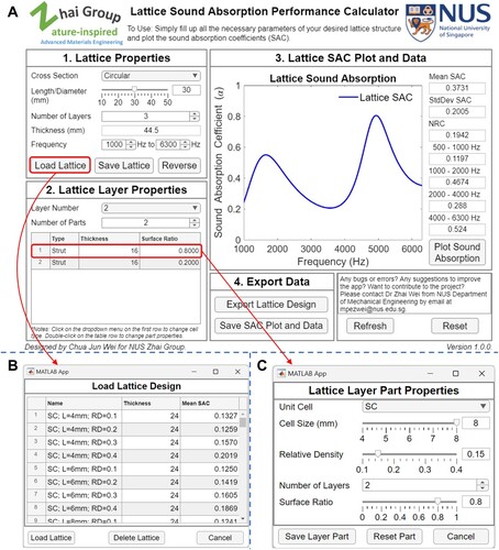
Next, one proceeds to change the properties of each lattice layer. He can choose the lattice layer to change using the drop-down menu. For each layer, the number of lattice parts to be arranged in parallel is specified and the table will populate with the data of the individual parts. Initially, the lattice parts were initialised with some default geometrical settings. One may double-click one of the rows of the table to change the part properties, in which the GUI for editing the part properties as shown in C will show up. Here, one can change the unit cell, cell size, RD, number of repetitions, and surface ratio. The thickness of the lattice sound absorber will be calculated automatically every time changes to the lattice design are made. There are also provisions for a user to save a lattice design into the library so that he may load it in another session. It is noted that there will be instances where the thicknesses of the lattice parts of a particular lattice layer are not equal, or the surface ratios of the parts do not equate to one. In such cases, the user may click the ‘Refresh’ or ‘Plot Sound Absorption’ buttons in the GUI to re-calculate the thicknesses and number of layers for each lattice layer part to align with the part with the largest thickness value. The surface ratios will also be scaled automatically such that the sum will now be equal to one.
Once the lattice design has been confirmed, one can calculate the SAC. The app plots out the SAC and provides statistics on the sound absorption performance of the designed lattice, such as the mean, standard deviation, and noise reduction coefficient (NRC). The NRC is defined as the average of the SACs at 250, 500, 1000, and 2000 Hz. Mean SACs for various frequency bands were shown which aids in lattice sound absorber design for targeted frequency ranges. One can export the SAC plot and statistics into a figure file and text file respectively. Lastly, one can export the lattice design into an external file for reference. The text file contains information on the lattice sound absorber as finetuned in the application itself, as well as information on the individual layers and parts. The file contains all the necessary information for one to draw the whole lattice in another computer-aided design (CAD) software. This facilitates the fabrication of lattice using 3D printing or additional analysis of the lattice such as mechanical properties.
This computer application leverages heavily on object-oriented programming (OOP) to define usage behaviour. This is a computer programming model that organises the software design solution around the use of objects and data. An object can be defined as a data field that has unique attributes and behaviour. This programming model was adopted due to its ease in handling modularity inherent in lattice design. Also, this model allows for ease of application enhancements such as the inclusion of more lattice unit cell architectures and mathematical models, as well as additional functionalities. The unit cell library may contain more kinds of lattice designs in the future.
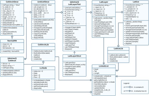
The Unified Modeling Language (UML) class diagram showing the classes of the LattSAC application is shown in . Here, it was notable that the key principles of OOP such as encapsulation, abstraction, inheritance, and polymorphism were utilised heavily. Encapsulation ensures that all important information about the lattice, its layers, and unit cells, are contained inside the respective objects while exposing only the necessary information through the application GUI. In particular, information on the mathematical models was not made public so that the users do not need to be concerned about how the acoustic parameters and SAC were calculated in the application, which greatly simplifies the use of the application. Abstraction and inheritance worked hand-in-hand such that any future additions and enhancements to the applications may be made more intuitive and orderly. For example, to add information about the plate unit cell architectures, one can simply inherit from the CellArch superclass and define the necessary properties and methods. Lastly, polymorphism allows some commonly-used methods such as ‘calcTMM' to exhibit different behaviour based on the properties of the lattice layer, hence ensuring that each type of lattice layer design has the correct mathematical models embedded within.
Figure 5. The Unified Modeling Language (UML) class diagram showing the classes of the LattSAC application, including their attributes, methods, and the relationships between classes.
As the first implementation of this software, the LattSAC software contains a limited number of unit cells and the available functionalities were limited. Therefore, the software was programmed in a manner that facilitates continuous improvements in the contents of the databases and the functionalities. It is desired to add many different types of lattice unit cells into the cell architecture library, such as plate lattices, lattices with micro-perforated plates, hollow strut lattices, TPMS lattices, and hybrids of the above lattice types. This allows further enhancements in the design space for the lattice sound absorbers that can be produced from the software. Also, additional useful functionalities may be programmed and pushed into the application alongside the addition of data from the above unit cells. These functionalities include the ability to calculate the sound transmission coefficients of the heterogeneous lattices, and the ability to recommend a heterogenous lattice given a target acoustic property and geometrical constraints.
4. Further discussions
Firstly, due to the large design freedom concerning the design of unit cells, the application of mathematical models such as the MMC model may seem tedious as the values of ,
and
have to be assigned based on individual unit cell geometries. This difficulty is one possible reason why many researchers chose to use finite element methods to relate the lattice geometries to the non-acoustic parameters in the DB and JCA models, or to simulate the acoustic properties directly. While the conventional approaches were viable and accurate, it can be problematic when people interested in the acoustic properties of complex lattice sound absorbers do not have access to such finite element software, which is often locked behind a paywall. The computational demands for the finite element modelling of SAC of lattices are substantial due to geometric complexities, and they increase with the growing intricacy of the structures. This work overcomes the two problems above by relating all possible designs of strut lattice unit cells to a single simple cubic strut unit cell and introducing experimentally determined correction factors to the strut length and width, as well as the use of semi-analytical mathematical models in the form of the MMC model and associated regression models. For instance, the SAC calculations for each of the heterogeneous samples took less than 5 minutes using the application, as compared to approximately 3 hours for a single homogeneous lattice when simulated using the COMSOL Multiphysics Thermoviscous Acoustics module. Hence, this work gives people interested in lattice sound absorbers an incentive to vary their lattice designs radically by introducing as many distinct layers and parts as desired without worrying about significant time and memory costs.
Secondly, the determination of the correction factors and
through experiments and statistical regression was less reported in the literature. The variable
represents an end correction for the air resistance of the system and is mainly dependent on the pore shape, thickness, and surface finish quality. Various values of
have been proposed by researchers, such as 0.5 by Maa [Citation32], or either 2 and 4, for a rounded and sharp-edged pore finish, respectively [Citation54]. The variable
represents an end correction for the mass reactance of the system that is also dependent on the geometry of the pores and cavities of the system. Ingard [Citation55] suggested a universal correction term for any geometry, given by
where
refers to the area of the pore. For a circular pore,
which is the value adopted by many other researchers using the model. It was noted in previous works that such a value of
was too crude a correction factor to be used for the accurate calculation of lattice acoustic properties [Citation56]. Afterward, Ingard proposed that
should decrease in value with increasing surface porosity. Other researchers argue that
should be dependent on the perforation ratio [Citation57] or the proximity of the pore from the cell wall [Citation56]. Essentially,
was heavily dependent on the geometry of the lattice unit cells and pores and hence should be determined individually for every case. Preliminary work on the SACs of SC-Truss lattices documented a process of determining appropriate expressions for
and
for the accurate modelling of SAC using the MMC model [Citation56]. Then,
was determined to be a function of
and the number of layers
, while
was a piecewise function of the perforation ratio
. This work generalises the modelling process by setting both correction factors as functions of cell size and RD, due to the complexities in determining the geometrical parameters of MPPs directly from the various lattice geometry. Overall, this research work was a valuable contribution to the acoustics and materials research community in the design of strut-based lattice sound absorbers for practical applications due to the potential in modelling the acoustic properties with great accuracies.
Thirdly, as mentioned earlier, there exists lattice design software such as those from Maskery et al. that aims to generate lattice geometries based on user input. However, it was found that most of the software takes into account the mechanical properties of the designed lattice structures due to an abundance of data from the scientific literature, with little regard for their acoustic properties. The use of current methods for acoustics modelling presents significant barriers to entry for the industries, mainly associated with the hiring of people skilled in acoustics modelling and the purchase of high-performance computing hardware and software. With this research work, we aim to develop one of the first lattice design software that assists in the design of lattice structures for acoustic-based applications so that the design process for such absorbers may be hastened. This may potentially result in much time and cost savings for the design of lattice-based acoustic materials for practical applications.
5. Conclusions
In this work, a lattice sound absorption software named LattSAC was developed to assist engineers and designers working on lattice sound absorbers by inputting the lattice geometrical parameters and outputting feedback on the sound absorption performance such as the SAC and statistics. This software leverages heavily OOP principles and the categorisation of the individual components of the lattice structure as objects to model and calculate the SAC. Hidden within the methods of the lattice objects was the semi-empirical MMC model which makes use of correction factors and the TMM to model the acoustic properties of homogeneous or heterogeneous lattice sound absorbers with high accuracies. The semi-empirical mathematical models used to calculate the strut width and the correction factors were trained using experimental data to output highly accurate predictions. This work boasts high prediction accuracies and potential time and cost savings in the development of lattice-based acoustic materials. It is expected that the application will receive further additions to the unit cell library to reflect the ever-expanding research landscape of lattice-based acoustic materials. Also, further enhancements to the application will be added to enhance its usability. The overall aim of the design software is to significantly narrow the gaps between lattice sound absorber development from the laboratory to the industry for practical applications.
Author contribution statement
Jun Wei Chua: Conceptualisation, Methodology, Software, Validation, Formal Analysis, Investigation, Data Curation, Writing – Original Draft, Visualisation, Supervision.
Zhejie Lai: Software, Investigation.
Xinwei Li: Conceptualisation, Methodology, Software, Writing – Review and Editing, Supervision.
Wei Zhai: Resources, Visualisation, Supervision, Project Administration, Finding Acquisition.
Supplemental Material
Download MS Word (1.1 MB)Disclosure statement
No potential conflict of interest was reported by the author(s).
Data availability statement
The data that support the findings of this study are available from the corresponding author, Dr. Wei Zhai, upon reasonable request.
Additional information
Funding
References
- Muzet A. Environmental noise, sleep and health. Sleep Med Rev. 2007;11(2):135–142. doi:10.1016/j.smrv.2006.09.001
- Kumar S, Lee H. The present and future role of acoustic metamaterials for architectural and urban noise mitigations. Acoustics. 2019;1(3):590–607. doi:10.3390/acoustics1030035
- Jariwala HJ, Syed HS, Pandya MJ, et al. (2017). Noise pollution & human health: a review. In Noise and air pollution: challenges and opportunities.
- Nelson DI, Nelson RY, Concha-Barrientos M, et al. The global burden of occupational noise-induced hearing loss. Am J Ind Med. 2005;48(6):446–458. doi:10.1002/ajim.20223
- Cao L, Fu Q, Si Y, et al. Porous materials for sound absorption. Compos Commun. 2018;10:25–35. doi:10.1016/j.coco.2018.05.001
- Berardi U, Iannace G. Predicting the sound absorption of natural materials: best-fit inverse laws for the acoustic impedance and the propagation constant. Appl Acoust. 2017;115:131–138. doi:10.1016/j.apacoust.2016.08.012
- Taban E, Tajpoor A, Faridan M, et al. Acoustic absorption characterization and prediction of natural coir fibers. Acoust Australia. 2019;47(1):67–77. doi:10.1007/s40857-019-00151-8
- Hou Y, Quan J, Thai BQ, et al. Ultralight biomass-derived carbon fibre aerogels for electromagnetic and acoustic noise mitigation. J Mater Chem A. 2022;10(42):22771–22780. doi:10.1039/D2TA06402B
- Rapisarda M, Malfense Fierro GP, Meo M. Ultralight graphene oxide/polyvinyl alcohol aerogel for broadband and tuneable acoustic properties. Sci Rep. 2021;11(1):10572. doi:10.1038/s41598-021-90101-0
- Li X, Yu X, Chua JW, et al. Microlattice metamaterials with simultaneous superior acoustic and mechanical energy absorption. Small. 2021;17(24):e2100336. doi:10.1002/smll.202100336
- Rice HJ, Kennedy J, Göransson P, et al. Design of a Kelvin cell acoustic metamaterial. J Sound Vib. 2020;472:115167. doi:10.1016/j.jsv.2019.115167
- Yang W, An J, Chua CK, et al. Acoustic absorptions of multifunctional polymeric cellular structures based on triply periodic minimal surfaces fabricated by stereolithography. Virtual Phys Prototyp. 2020;15(2):242–249. doi:10.1080/17452759.2020.1740747
- Li X, Yu X, Zhai W. Additively manufactured deformation-recoverable and broadband sound-absorbing microlattice inspired by the concept of traditional perforated panels. Adv Mater. 2021;33(44):e2104552. doi:10.1002/adma.202104552
- Liu J, Chen T, Zhang Y, et al. On sound insulation of pyramidal lattice sandwich structure. Compos Struct. 2019;208:385–394. doi:10.1016/j.compstruct.2018.10.013
- Zhang Y, Zhu Z, Sheng Z, et al. Sound absorption properties of the metamaterial curved microperforated panel. Int J Mech Sci. 2024;268; doi:10.1016/j.ijmecsci.2024.109003
- Gao N, Zhang Z, Deng J, et al. Acoustic metamaterials for noise reduction: a review. Adv Mater Technol. 2022;7(6). doi:10.1002/admt.202100698
- Pelat A, Gautier F, Conlon SC, et al. The acoustic black hole: A review of theory and applications. J Sound Vib. 2020;476; doi:10.1016/j.jsv.2020.115316
- Yang X, Wen G, Jian L, et al. Archimedean spiral channel-based acoustic metasurfaces suppressing wide-band low-frequency noise at a deep subwavelength. Mater Des. 2024;238; doi:10.1016/j.matdes.2024.112703
- Zangeneh-Nejad F, Fleury R. Active times for acoustic metamaterials. Rev Phys. 2019;4. doi:10.1016/j.revip.2019.100031
- Schaedler TA, Carter WB. Architected cellular materials. Annu Rev Mater Res. 2016;46(1):187–210. doi:10.1146/annurev-matsci-070115-031624
- Rashed MG, Ashraf M, Mines RAW, et al. Metallic microlattice materials: A current state of the art on manufacturing, mechanical properties and applications. Mater Des. 2016;95:518–533. doi:10.1016/j.matdes.2016.01.146
- Ashby MF. The properties of foams and lattices. Philos Trans Royal Soc Lond A. 2006;364(1838):15–30. doi:10.1098/rsta.2005.1678
- Zieliński TG, Opiela KC, Pawłowski P, et al. Reproducibility of sound-absorbing periodic porous materials using additive manufacturing technologies: round robin study. Addit Manuf. 2020;36:101564. doi:10.1016/j.addma.2020.101564
- Boulvert J, Costa-Baptista J, Cavalieri T, et al. Acoustic modeling of micro-lattices obtained by additive manufacturing. Appl Acoust. 2020;164; doi:10.1016/j.apacoust.2020.107244
- Li X, Yu X, Zhai W. Less is more: Hollow-Truss microlattice metamaterials with dual sound dissipation mechanisms and enhanced broadband sound absorption. Small. 2022;18(44):e2204145. doi:10.1002/smll.202204145
- Delany ME, Bazley EN. Acoustical properties of fibrous absorbent materials. Appl Acoust. 1970;3(2):105–116. doi:10.1016/0003-682X(70)90031-9
- Champoux Y, Allard J-F. Dynamic tortuosity and bulk modulus in air-saturated porous media. J Appl Phys. 1991;70(4):1975–1979. doi:10.1063/1.349482
- Johnson DL, Koplik J, Dashen R. Theory of dynamic permeability and tortuosity in fluid-saturated porous media. J Fluid Mech. 2006;176(1). doi:10.1017/s0022112087000727
- Biot MA. Theory of propagation of elastic waves in a fluid-saturated porous solid. II. higher frequency range. J Acoust Soc Am. 1956;28(2):179–191. doi:10.1121/1.1908241
- Boulvert J, Cavalieri T, Costa-Baptista J, et al. Optimally graded porous material for broadband perfect absorption of sound. J Appl Phys. 2019;126(17). doi:10.1063/1.5119715
- Komkin AI, Mironov MA, Bykov AI. Sound absorption by a Helmholtz resonator. Acoust Phys. 2017;63(4):385–392. doi:10.1134/S1063771017030071
- Maa D-Y. Potential of microperforated panel absorber. J Acoust Soc Am. 1998;104(5):6.
- Doutres O, Ouisse M, Atalla N, et al. Impact of the irregular microgeometry of polyurethane foam on the macroscopic acoustic behavior predicted by a unit-cell model. J Acoust Soc Am. 2014;136(4):1666–1681. doi:10.1121/1.4895695
- Doutres O, Atalla N, Dong K. A semi-phenomenological model to predict the acoustic behavior of fully and partially reticulated polyurethane foams. J Appl Phys. 2013;113(5). doi:10.1063/1.4789595
- Yang L, Wei Chua J, Li X, et al. Superior broadband sound absorption in hierarchical ultralight graphene oxide aerogels achieved through emulsion freeze-casting. Chem Eng J. 2023;469; doi:10.1016/j.cej.2023.143896
- Yu X, Lu Z, Zhai W. Enhancing the flow resistance and sound absorption of open-cell metallic foams by creating partially-open windows. Acta Mater. 2021;206:116666. doi:10.1016/j.actamat.2021.116666
- Zhai W, Yu X, Song X, et al. Microstructure-based experimental and numerical investigations on the sound absorption property of open-cell metallic foams manufactured by a template replication technique. Mater Des. 2018;137:108–116. doi:10.1016/j.matdes.2017.10.016
- Maskery I, Parry LA, Padrão D, et al. FLatt pack: a research-focussed lattice design program. Addit Manuf. 2022;49; doi:10.1016/j.addma.2021.102510
- Raju SKK, Onkar PS. Lattice_Karak: Lattice structure generator for tissue engineering, lightweighting and heat exchanger applications. Softw Impacts. 2022;14; doi:10.1016/j.simpa.2022.100425
- Al-Ketan O, Abu Al-Rub RK. MSLattice: a free software for generating uniform and graded lattices based on triply periodic minimal surfaces. Mater Des Process Commun. 2020;3(6). doi:10.1002/mdp2.205
- Bonatti C, Mohr D. Large deformation response of additively-manufactured FCC metamaterials: from octet truss lattices towards continuous shell mesostructures. Int J Plasticity. 2017;92:122–147. doi:10.1016/j.ijplas.2017.02.003
- Dong L, Deshpande V, Wadley H. Mechanical response of Ti–6Al–4 V octet-truss lattice structures. Int J Solids Struct. 2015;60-61:107–124. doi:10.1016/j.ijsolstr.2015.02.020
- Hanks B, Berthel J, Frecker M, et al. Mechanical properties of additively manufactured metal lattice structures: data review and design interface. Addit Manuf. 2020;35:101301. doi:10.1016/j.addma.2020.101301
- Lai Z, Zhao M, Lim CH, et al. Experimental and numerical studies on the acoustic performance of simple cubic structure lattices fabricated by digital light processing. Mater Sci Addit Manuf. 2022;1(4):1–12.
- Jiménez N, Umnova O, Groby J-P. (2021). Acoustic waves in periodic structures, metamaterials, and porous media. Topics in Applied Physics.
- Morse PM, Uno Ingard K. Theoretical acoustics, international series in pure and applied physics. New York: McGraw-Hill; 1968.
- Verdiere K, Panneton R, Elkoun S, et al. Transfer matrix method applied to the parallel assembly of sound absorbing materials. J Acoust Soc Am. 2013;134(6):4648. doi:10.1121/1.4824839
- Ridella S, Rovetta S, Zunino R. Circular backpropagation networks for classification. IEEE Trans Neural Netw. 1997;8(1):84–97. doi:10.1109/72.554194
- Ding SQ, Xiang C. (2004). From multilayer perceptrons to radial basis function networks: a comparative study. Paper presented at the IEEE Conference on Cybernetics and Intelligent Systems, 2004.
- Chua JW, Li X, Li T, et al. Customisable sound absorption properties of functionally graded metallic foams. J Mater Sci Technol. 2022;108:196–207. doi:10.1016/j.jmst.2021.07.056
- ASTM. ASTM E1050-19, standard test method for impedance and absorption of acoustical materials using a tube, two microphones and a digital frequency analysis system. West Conshohocken (PA): ASTM International; 2019.
- Jaouen L, Gourdon E, Gle P. Estimation of all six parameters of Johnson-Champoux-Allard-Lafarge model for acoustical porous materials from impedance tube measurements. J Acoust Soc Am. 2020;148(4):1998. doi:10.1121/10.0002162
- Bies DA, Hansen CH, Howard CQ. Engineering noise control. 6th ed. Boca Raton: CRC Press; 2024.
- Guo Y, Allam S, Åbom M. (2008). Micro-perforated plates for vehicle applications. Paper presented at the 37th International Congress and Exhibition on Noise Control Engineering, Shanghai, People’s Republic of China October, 2008.
- Ingard U. On the theory and design of acoustic resonators. J Acoust Soc Am 1953;25(6):1037–1061. doi:10.1121/1.1907235
- Li X, Yu X, Zhao M, et al. Multi-level bioinspired microlattice with broadband sound-absorption capabilities and deformation-tolerant compressive response. Adv Funct Mater. 2022;33(2):2210160. doi:10.1002/adfm.202210160
- Okuzono T, Nitta T, Sakagami K. Note on microperforated panel model using equivalent-fluid-based absorption elements. Acoust Sci Technol. 2019;40(3):221–224. doi:10.1250/ast.40.221