
 ?Mathematical formulae have been encoded as MathML and are displayed in this HTML version using MathJax in order to improve their display. Uncheck the box to turn MathJax off. This feature requires Javascript. Click on a formula to zoom.
ABSTRACT
In bone tissue engineering, the search for improved repair methods is crucial, given the drawbacks of traditional strategies like donor site issues and immune rejection. Addressing these challenges, this paper introduces an innovative GelMA/Bentonite composite bioink for 3D bioprinting, designed to create scaffolds that closely emulate native bone tissue. GelMA is selected for its biocompatibility and modifiable mechanics, while Bentonite's mineral richness and ion exchange capacity are harnessed to enhance scaffold structure and promote an osteogenic microenvironment. This research marks the inaugural incorporation of Bentonite into a bioink, a significant stride forward given its established safety in pharmaceuticals and versatility across industries. This bioink formulation signifies a breakthrough in bone tissue engineering, aiming to improve the osteointegration and regeneration of bone tissue. Combining Bentonite with GelMA marks a key step in creating bioinks that enhance bone healing, potentially transforming scaffold-based bone regeneration and pioneering the use of natural nanomaterials in medicine.
1. Introduction
Bone tissue engineering is a dynamic and innovative field at the forefront of regenerative medicine, tackling the complex challenge of repairing and regenerating bone tissue damaged by trauma, disease, or congenital defects [Citation1,Citation2]. While traditional bone repair techniques like autografting and allografting have been the cornerstone of treatments, their limitations, including donor site morbidity, limited graft supply, and potential for immune rejection, have spurred the development of alternative approaches [Citation3–5]. Three-dimensional (3D) bioprinting emerges as a revolutionary technology in this landscape, offering precise control over cell and biomaterial deposition to create constructs that faithfully replicate the complex architecture of native bone tissue [Citation6]. This cutting-edge method transcends the constraints of traditional techniques, enabling the generation of patient-specific grafts with customised shapes and functionalities that promise better integration and reduced rejection rates [Citation7,Citation8]. The convergence of multiple cell types and bioactive compounds within bioinks in 3D bioprinting not only simulates the native cellular milieu but also heralds enhanced osteointegration and regeneration, presenting a beacon of hope for complex orthopedic conditions [Citation9]. As bone tissue engineering evolves, 3D bioprinting is poised to redefine the paradigms of bone repair, potentially diminishing the current dependence on traditional grafting methods and revolutionising orthopedic treatment modalities [Citation10,Citation11].
Bioinks stand as the cornerstone of the 3D bioprinting paradigm, a palette of biomaterials meticulously curated for their printability and biological compatibility [Citation12]. Among these, Gelatin methacryloyl (GelMA) has emerged as a frontrunner, prized for its malleable properties and affinity for human tissue integration [Citation13]. As a derivative of natural gelatin, GelMA retains the cell-responsive features of its progenitor but with enhanced photocrosslinkable capabilities, allowing for rapid solidification under light exposure [Citation14]. This quality is indispensable for constructing scaffolds that not only support but actively participate in the healing process. The real breakthrough, however, occurs when GelMA converges with inorganic elements, particularly those that reflect the complex mineral gradient of the bone's extracellular matrix (ECM) [Citation15,Citation16]. These inorganic counterparts are not mere fillers; they recreate the bone's natural habitat, fostering an environment where cells can thrive mechanically and biologically [Citation17]. While hydroxyapatite has traditionally been the inorganic material of choice, mirroring the primary constitution of bone mineral, its application has limitations in terms of scaffold versatility and functional tunability [Citation18]. Although hydroxyapatite is outstanding in mimicking the mineral content of bones, its versatility in scaffold production is restricted. Its rigid structure and processing characteristics restrict the design of scaffolds with complex geometrical shapes and customised porous structures, which are crucial for cell migration, nutrient diffusion, and new tissue formation. The bioactivity and mechanical properties of hydroxyapatite scaffolds remain relatively fixed after manufacture, limiting their adaptability to different biological environments and therapeutic requirements. The search for alternative materials has become a pressing agenda in the quest to push the boundaries of scaffold performance [Citation19].
Bentonite, a material with vast reserves and a broad spectrum of applications, emerges as a novel and promising nanomaterial in the realm of bone tissue engineering [Citation20]. Beyond its established applications in industries such as brewing and wastewater treatment, bentonite is renowned for its rich mineral composition and ion exchange capacity [Citation21]. The primary component, montmorillonite, imparts bentonite with a unique platelet structure that endows it with viscoelastic properties, seldom found in natural materials [Citation22]. This layered silicate's ability to swell upon water absorption imparts scaffolds with a flexibility and toughness akin to living tissues [Citation23]. Compared to hydroxyapatite, scaffolds made from more adaptable materials like bentonite can have their mechanical and biological properties adjusted more readily to meet specific requirements. Bentonite, with its notable swelling behaviour and ion exchange capacity, can be utilised to create scaffolds with a highly porous structure that enhances cell infiltration and inward tissue growth [Citation24]. Moreover, the ion exchange characteristics of bentonite can be utilised to incorporate therapeutic ions that promote bone healing and regeneration. The rheological properties of bentonite allow for the production of scaffolds with customised mechanical properties and degradation rates, thus better controlling the physical environment of the scaffold. This adaptability makes bentonite an attractive option for creating patient-specific scaffolds that can adapt to various defect sizes and shapes. The safety and biocompatibility of bentonite are well-documented, underscored by its use in pharmaceuticals such as the antidiarrheal medication Montmorillonite powder, which is ingested safely by humans [Citation25]. This established track record for human safety is a testament to its non-toxicity and further endorses its potential in medical applications [Citation26]. Bentonite is typically more cost-effective and more readily available than hydroxyapatite, making it a practical choice for widespread application and commercialisation in bone tissue engineering. When integrated with GelMA, bentonite imparts a composite bioink with enhanced structural integrity and a microenvironment optimised for osteoinduction. This symbiotic environment is essential for promoting cellular adhesion, proliferation, and differentiation, guiding the intricate cascade of cellular events that result in bone formation [Citation27]. The integration of bentonite into GelMA bioinks is not merely an advancement but represents a synthesis of organic matrix and inorganic nanoarchitecture, poised to set a new standard for scaffold-based bone regeneration [Citation28].
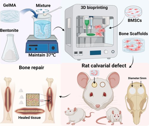
This paper introduces a ground-breaking bioink, a GelMA/Bentonite composite, ingeniously combining Gelatin methacryloyl's biocompatibility with the nanostructured mineral content of Bentonite, a newcomer in the realm of 3D bioprinting for bone repair. This novel composite material is designed to leverage the inherent properties of GelMA and Bentonite, aiming not only to prepare bioinks for bone tissue engineering but also to produce supportive scaffolds for bone regeneration and repair (). The innovation of this research lies in its first-time use of Bentonite—an element with a rich legacy in various industrial applications and recognised for its substantial mineral makeup and ion exchange capacity—as an integral bioink component [Citation29,Citation30]. This selection is underpinned by Bentonite’s proven track record in pharmaceutical safety, offering reassurance of its non-toxicity and suitability for medical applications [Citation31]. The ensuing discourse will thoroughly explore the selection process for these materials, detailing how Bentonite's physicochemical properties complement GelMA's gel-like nature to improve scaffold printability and structural integrity. Furthermore, the anticipated synergistic outcomes—where Bentonite's osteoconductive capabilities enhance GelMA’s conducive cellular environment—are projected to have profound implications on bone tissue engineering, potentially setting new standards for bioink formulation and pioneering the use of natural nanomaterials in scaffold construction.
Figure 1. Schematic diagram of enhanced bone regeneration GelMA/Bentonite.
2. Materials and methods
2.1. Material preparation
Obtained from the Suzhou Institute of Smart Manufacturing in Suzhou, Jiangsu, China, were the EFL-GM-60 GelMA with 60±5% methacrylation and 100–200 kDa molecular weight, clear to less than 20 NTU in solution; the photoinitiator Lithium Phenyl (2,4,6-trimethylbenzoyl) phosphinate (LAP), CAS 85073-19-4, 99.8% pure, with a molecular weight of 296.23; and a 405 nm, 5W blue light source, model EFL-LS-1600-405. Sourced from Macklin, Shanghai, China, Bentonite (CAS 1302-78-9) is composed of Al2O3·4(SiO2)·H2O, with a molecular weight of 360.31 g/mol and a density ranging from 2 to 3 g/cm³.
2.2. Preparation of composite bioinks.
GelMA with a grafting degree of 60 was utilised. A 5 wt% concentration solution of GelMA was prepared using deionised water. Subsequently, bentonite was incorporated at concentrations of 1.25 , 2.5 , and 5 wt%, and the mixture was thoroughly stirred at 37 °C. Before 3D printing, 0.25 wt% of the photoinitiator LAP was added.
2.3. Chemical structure of the bioinks
2.3.1. FTIR-ATR
Chemical composition of the scaffolds was analyzed using FTIR-ATR on a Nicolet-6700 spectrometer (Thermo, USA), featuring a diamond crystal and ZnSe lens, set at 45 degrees incident angle. Spectral data were collected between 500 and 4000 cm−1, encompassing 32 scans at a resolution of 4 cm−1.
2.3.2. X-ray diffraction
Crystal structure analysis was conducted using X-ray diffraction (XRD) on a Rigaku D/max 2550 V powder diffractometer (Japan). Parameters included a 40 kV voltage, 250 mA current, a 10° to 80° scanning range, 0.1° step size, and a scanning speed of 1°/min.
2.3.3. Thermogravimetric analysis (TGA)
Thermogravimetric analysis (TGA) was conducted to assess the thermal properties of the samples. The analyses were carried out using a TGA Q500 (TA Instruments, USA) instrument, with a temperature range extending from ambient to 650 °C at a heating rate of 10 °C/min, in a nitrogen environment.
2.3.4. Contact angle
Contact angle measurements were performed using a contact angle goniometer (OCA15EC, EASTERN-DATAPHY, China) to assess the surface wettability of the samples. A sessile drop method was employed using a contact angle goniometer. A 5 µL droplet of distilled water was gently placed on the sample surface, and the angle formed at the liquid–solid interface was immediately captured with a high-resolution camera. The contact angle was then calculated using image analysis software. Measurements were conducted at room temperature, and each sample was tested in six replicates to ensure reproducibility of results.
2.3.5. X-ray photoelectron spectroscopy (XPS)
XPS analysis of samples was performed using a Thermo Scientific ESCALAB Xi+ system equipped with a monochromatized Al Kα source (E = 1486.68 eV). Prior to analysis, the samples were ground into a fine powder and evenly spread on the XPS sample holder. Survey scans were conducted with a pass energy of 100 eV to determine the elemental composition of the sample surfaces. High-resolution scans were subsequently performed for selected elements with a pass energy of 20 eV to obtain detailed information on their chemical states. The work function of the system was set at 4.54 eV. Data analysis was carried out using XPS software to process and fit the spectra.
2.3.6. Inductively coupled plasma optical emission spectroscopy (ICP-OES)
To verify the ion exchange capability of the scaffolds, the printed scaffolds were immersed in simulated body fluid (SBF) for 10 days, and the ion concentrations in the solution before and after immersion were measured using ICP-OES. ICP-OES analysis was conducted using an Agilent 5800 instrument (Agilent, USA). The operational parameters were set as follows: RF Power at 1200W, Plasma flow at 12 L/min, Auxiliary flow at 1 L/min, Nebulizer flow at 0.7 L/min, Sample uptake delay at 15 s, Instrument stabilisation delay at 15 s. Three replicates were performed for each group of samples.
2.4. Physicochemical characteristics of the bioinks
2.4.1. Rheological property
Rheological properties of the hydrogels were characterised using a rotational rheometer (TA instruments, USA). Initially, temperature-dependent storage (G’) and loss (G'’) moduli were determined through an oscillatory temperature sweep from 0 °C to 40 °C at 10 rad s−1 and 5% shear stress. To evaluate the viscoelastic behaviour of the hydrogel, samples were subjected to a frequency sweep from 0.1 to 10 Hz at 25 °C, maintaining a constant strain within the linear viscoelastic region. G’ and G'’ were recorded. All measurements were repeated thrice to ensure consistency.
2.4.2. Mechanical property
Mechanical properties of the hydrogels were assessed using an electronic universal testing machine (WDW-1, Shanghai Songdun Instrument Manufacturing & Co. G, China). Samples were prepared using molds to form cylindrical specimens with a diameter of 7 mm and a height of 8 mm and subjected to uniaxial compression tests. The samples were exposed to a blue light source for 3 min to ensure thorough curing. Prior to testing, each hydrogel sample was equilibrated at room temperature for 30 min. The compression rate was set at 1 mm/min, and the tests were conducted until 70% strain was achieved. The stress–strain data were recorded, from which the Young's modulus, tensile strength, and elongation at break were calculated. To ensure reliability, each measurement was performed in six replicates.
2.4.3. Swelling property
To evaluate the swelling degree of different bioink materials, cylindrical scaffolds (7 mm × 7 mm × 2 mm) were fabricated using standard molds and then exposed to ultraviolet light (5W, 405 nm) for 3 min. These were freeze-dried, and the dry weight (Wdry) of each of the 6 replicates was recorded. The samples were then immersed in PBS at 37 °C for various durations. Post-immersion, excess water was removed using filter paper, and the swollen weight (Wwet) of each sample was measured. The swelling ratio was calculated using the EquationEquation (1)(1)
(1) [Citation32].
(1)
(1)
2.4.4. Degradation property
Samples for degradation assessment, prepared similarly to the swelling analysis, were incubated in PBS at 37 °C, with PBS refreshed weekly. Post-immersion at designated time intervals, they were lyophilised and weighed (Wt), with initial dry weight recorded as Wdry. The degradation ratio was calculated using the EquationEquation (2)(2)
(2) [Citation33].
(2)
(2)
2.5. Bone Marrow Stromal Cells (BMSCs) isolation and culture
To extract rat BMSCs, the femurs and tibias are aseptically removed from euthanized rats. The bone marrow is flushed out using a syringe filled with culture medium. The cell suspension is then centrifuged, and the supernatant is discarded. The pellet is resuspended and cultured in appropriate growth medium (α-MEM with 1% penicillin–streptomycin, and 10% FBS) under standard conditions. After reaching confluence, cells are trypsinized and subcultured. Media was refreshed every three days, and cells from passages 4–5 were utilised for experiments. Three replicates were performed for each group of samples.
2.6. 3d bioprinting process and structural observation
2.6.1. 3d printing of bioinks
Each group's bioink was sterilised using UV irradiation and then mixed with sterile LAP solution. 5×10⁶ ml−1 BMSCs were incorporated into the sterilised bioink to prepare a homogeneous bioink. This bioink was subsequently loaded into a 3D bioprinter (Bio Architect®WS, Regenovo, China) equipped with a 22 G (410 µm) nozzle. The printing bed and cartridge were maintained at 15 °C to ensure hydrogel stability. The speed of the nozzle movement was set to 4–8 mm/s to balance resolution and time efficiency. The air pressure was adjusted to 0.05–0.2 MPa to achieve uniform layer deposition. Manufactured using a layer-by-layer approach during the printing process, each sample was integrated with a total of four layers. The layer thickness was maintained at 200 µm to construct the desired 3D structure. Post-deposition, the bioprinted scaffolds were crosslinked using UV light (3 W, 405 nm) for 10 s to enhance structural integrity. After printing, the constructs were incubated in a culture medium at 37 °C for 24 h to ensure complete crosslinking and to assess their stability in physiological conditions. The final structures were then evaluated using microscopy for dimensional accuracy and structural integrity.
2.6.2. Printability test
Printability was assessed using a stereomicroscope (Stemi 508, Carl Zeiss, Germany), with printability factor (Pr) and diffusion rate (Dfr) calculated using pore characteristics measured via Photoshop. EquationEquation (3)(3)
(3) [Citation34] was used to compute the Pr, taking into account the pore circularity (C), perimeter (L), and area (A). Pore circularity is defined as 4π(area/perimeter²). This parameter is used to assess the roundness of pores within the scaffold, with values closer to 1 indicating more circular pores.
(3)
(3) The Dfr was calculated using EquationEquation (4)
(4)
(4) [Citation35], considering Atf as the theoretical pore area and Aaf as the actual pore area.
(4)
(4)
2.6.3. Morphology of printed scaffolds
The scaffolds were first prepared for SEM by undergoing a freeze-drying process to remove moisture. Following this, to enhance conductivity, the dried scaffolds were sputter-coated with a thin layer of platinum. The coated samples were then mounted on SEM stubs using conductive adhesive. Images were captured using a GeminiSEM 300 (Carl Zeiss, Germany) in SE2 mode at various magnifications, applying a 5 kV voltage. The instrument was equipped with an Energy Dispersive Spectroscopy (EDS) analyzer (AztecLive Ultim Max 100) for elemental analysis.
2.7. Cell viability assay
2.7.1. Live/dead staining
BMSCs viability on scaffolds was evaluated at 1, 4, and 7 days post-seeding using a live/dead staining kit (Calcein AM/PI Double Stain Kit, MKBio, China). The scaffolds were seeded with BMSCs at a density of 1×10⁶ mL−1. The cells were allowed to adhere to the scaffold for 4 h prior to the addition of the culture medium. The procedure entailed incubating the scaffolds in 2 μM calcein-AM and 4 μM propidium iodide (PI) for 15 min at 37 °C. Living BMSCs exhibited green fluorescence from calcein-AM, while dead cells showed red fluorescence due to PI. Fluorescence microscopy (FV3000, Olympus, Japan) was utilised to document and assess cell viability over these intervals.
2.7.2. CCK-8 assays
To evaluate the proliferation of BMSCs on the scaffolds, the proliferation was assessed using the Cell Counting Kit-8 (CCK-8, MKBio, China) at intervals of 1, 4, and 7 days after seeding the cells. Fresh medium replaced the old one, and the cells were incubated at 37 °C for 1 h with a 10% solution of CCK-8. Post-incubation, a multifunction microplate reader (BioTek, USA) was used to measure the optical density (OD) at a wavelength of 450 nm.
2.8. In vitro osteogenesis capacity
The osteogenic capability of cells in each group of scaffolds was assessed by detecting the expression of osteogenic genes through Real-time PCR analysis. Initially, the scaffolds underwent lysis using GelMA lysis buffer, after which total mRNA was extracted using RNAiso Plus (Trizol, Beyotime, China). The extracted RNA was then converted into cDNA with the RevertAid kit (Takara, Japan). This cDNA underwent duplicate amplification using the RT–PCR kit (Beyotime, China) in conjunction with the LightCycler96 system (Roche, Switzerland). The purpose of this procedure was to analyze the expression of inflammatory cytokines and genes linked to osteogenesis, such as Runt-related Transcription Factor 2 (Runx2), Osteopontin (OPN), and Collagen I (COL1A1), with primer sequences listed in Table S1. β-actin, an internal control gene, was used for normalisation purposes.
2.9. Animal studies
The Institute of Translational Medicine, Shanghai University's Animal Ethics Committee approved all animal-involved surgical procedures under the reference ECSHU 2020-001. These procedures aligned with the National Institutes of Health's standards for laboratory animal care and use (NIH Publications No. 8023, revised 1978). These rats were randomly divided into four groups: the GelMA group, the GelMA/1.25 wt% bentonite group, the GelMA/2.5 wt% bentonite group, and the GelMA/5 wt% bentonite group. Subsequent nude mice experiments were also randomly divided into the aforementioned four groups.
2.9.1. In vivo degradability study
For the in vivo degradation study, bioink labelled with Cy5.5 was first synthesised. The amino groups in biomolecules react with Sulfo-Cy5.5 NHS ester, forming stable amide bonds and thus incorporating Cy5.5 into the biomacromolecules. Each hydrogel variant was combined with an equal molar amount of Sulfo-Cy5.5 NHS ester (1:1 mol ratio) in 5 mL deionised water. This mixture was then stirred in the dark at 4 °C for 24 h. Scaffolds printed with Cy5.5-tagged bioinks were subcutaneously inserted into four groups of rats (six per group), remaining in situ for 35 days. The fluorescence emitted by the implanted biomaterials was measured at various time points (0, 7, 14, 21, 28, and 35 days after implantation) using a small animal imaging system (BLT, AniView100, China).
2.9.2. In vivo mineralisation study
To investigate the mineralisation of scaffolds in vivo, various biologically material-infused hydrogel scaffolds were subcutaneously implanted into 8-week-old nude mice (six per group). These scaffolds were extracted after 2 and 4 weeks for Micro-computed tomography (micro-CT) analysis, aimed at assessing mineral deposition within the scaffold structure in a non-bone microenvironment. The calculation of mineral density and total mineral volume involves micro-CT image analysis to assess the mineral content within the organoids. This process includes processing the micro-CT images, followed by the application of specific thresholding techniques to quantitatively analyze the mineralised sections [Citation36].
2.9.3. Alkaline phosphatase (ALP) and Alizarin Red S (ARS) staining
For ALP and ARS staining of tissue sections from scaffolds implanted subcutaneously in nude mice for 4 weeks, the procedure begins with fixing the sections in 4% paraformaldehyde, followed by dehydration and paraffin embedding. Sections (5 μm thick) are prepared, deparaffinized in xylene, and rehydrated through a graded ethanol series. For ALP staining, an Alkaline Phosphatase Color Development Kit (Beyotime, China) was utilised, with the solution prepared according to the manufacturer's instructions to indicate ALP activity. For ARS staining, sections are immersed in Alizarin Red S solution (Beyotime, China), which binds to calcium deposits, signifying mineralisation. After staining, sections are washed, dehydrated, cleared, mounted, and examined under a microscope to assess both ALP activity and mineralisation, indicative of osteogenic differentiation and activity.
2.9.4. Calvarial defect models
Female SD rats, 8 weeks old, were employed for creating cranial defect models, encompassing a total of 24 rats. The study involved preparing and sterilising the cranial region of rats with povidone iodine. A circular bit created bilateral cranial defects of 5 mm diameter, ensuring no harm to the brain tissue. The bioprinted bone scaffolds were cut into cylinders with a diameter of 5 mm using a hollow ring drill of the same diameter, and filled the right-side defects in each rat, while the left-side defects served as controls. Post-operative care included skin disinfection and suturing for healing. Six rats from each group were sacrificed at 4 and 8 weeks post-implantation for analysis. The heart, liver, spleen, lung, and kidney of these rats were carefully extracted and conserved for further study. Blood samples, collected at the 4-week mark, underwent hematological and biochemical tests. The study also included assessing the in vivo toxicity of the hydrogel scaffolds through HE-stained histological examination. Additionally, micro-CT scans were performed on the cranial samples to analyze the integration of the hydrogel scaffolds at 4 and 8 weeks.
2.9.5. Micro-CT
Bone regeneration was assessed using a Skyscan 1172 micro-CT (50 kV, 60 µA, aluminum filter, 13.8 μm pixel size). Images were reconstructed with NRecon software and analyzed with CTAn for parameters like bone volume fraction (BV/TV) and bone mineral density (BMD). For 3D visualisation, CTVol software was used. Enhanced imaging for implanted scaffolds involved adjusting parameters to 65 kV and 80 µA. Data processing and image reconstructions were conducted using Skyscan's NRecon, CTAn, and CTVol software suites [Citation37].
2.9.6. Hematoxylin & eosin (HE) and Masson staining
Subcutaneously implanted scaffolds and calvarial samples were fixed in 4% paraformaldehyde (Servicebio, China), decalcified with 10% EDTA (Servicebio, China), and then paraffin-embedded. Sections of 5 µm thickness were prepared and stained using standard HE and Masson protocols. Representative images were captured with a panoramic DESK scanner (3DHISTECH, Budapest, Hungary).
2.9.7. Immunofluorescence tissue staining
Following preparation, calvarial specimens were processed for immunohistochemical staining. The sections underwent fixation, decalcification, paraffin embedding, and staining as per standard protocols. For new bone formation, OCN and OPN immunohistochemical fluorescence staining were used, while CD31/α-SMA immunofluorescence staining assessed vascular formation. Images of the stained sections were captured with a panoramic DESK scanner. Fluorescence intensity in different groups was quantitatively assessed using Image J software (Rawak Software Inc., Germany).
2.10. Statistical analysis
Data analysis utilised SPSS version 19.0 (IBM Corporation, USA), with results shown as mean ± SD. One-way ANOVA with Tukey's post hoc test and Kruskal–Wallis H-test with pairwise comparisons assessed statistical significance. Significance was indicated as follows: (*) p < 0.05, (**) p < 0.01, (***) p < 0.005, and (****) p < 0.001.
3. Results and discussions
3.1. Synthesis and characterisation of GelMA/bentonite bioinks
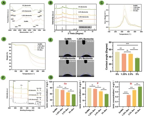
The GelMA/Bentonite composite bioinks have been examined using FTIR, XRD, and contact angle measurements to assess their chemical, crystalline, and surface hydrophilicity properties respectively (). The FTIR spectra indicate distinct absorption bands characteristic of GelMA and Bentonite (A). GelMA in FTIR spectroscopy is characterised by its distinctive peaks at 1630 cm−1 for C = O stretching of amide I, around 1540 cm−1 for N-H bending of amide II, and near 1720cm−1 for C = O stretching of methacryloyl groups. Bentonite is characterised by distinct peaks around 3695–3620 cm−1 for OH stretching, a significant Al-OH bending vibration at 912 cm−1, and notable Si-O stretching and bending vibrations in the 1000–1100 cm−1 and around 470 cm−1 regions, respectively. The presence of Bentonite in the composite is confirmed by the appearance of new peaks and the shift in wavenumber of certain absorption bands, which suggests interactions between the GelMA matrix and Bentonite particles. As the Bentonite content increases, these changes become more pronounced, indicating a stronger interaction within the composite. The XRD analysis reveals the crystalline structure of the bioinks (B). Pure GelMA shows a mostly amorphous pattern, while the introduction of Bentonite introduces peaks indicative of its crystalline nature. In X-ray diffraction (XRD) analysis, bentonite is characterised by a distinctive pattern, with its most prominent peak at 12.4° corresponding to the (001) plane, indicative of the basal spacing of the layers. Additionally, there are significant peaks at 24.9° associated with the (002) plane, 19.8° corresponding to the (110) plane, 35.0° related to the (130) plane, and 62.0° representing the (060) plane. These peaks collectively define the unique crystalline structure of bentonite, essential for understanding its mineral composition and applications in various scientific and industrial fields. The peak intensities (12.4°) increase with Bentonite content, confirming the successful integration of Bentonite and suggesting a possible reinforcement mechanism that could enhance the composite's mechanical properties. The thermal properties of composite materials with varying concentrations of bentonite and GelMA were evaluated using TGA (C-D). The results indicated that the pure GelMA sample (without bentonite) began to show significant weight loss at approximately 250 °C, suggesting lower thermal stability. With the incorporation of 2.5% GelMA/Bentonite, the significant weight loss point increased to around 275 °C, demonstrating a notable enhancement in thermal stability due to the addition of bentonite. As the bentonite concentration was further raised to 5% GelMA/Bentonite, this temperature point climbed to about 295 °C, underscoring the role of bentonite in improving thermal stability. However, when the bentonite concentration was reduced to 1.25% GelMA/Bentonite the significant weight loss temperature slightly decreased to around 266 °C, still higher than that of the pure GelMA sample. These findings suggest that the addition of bentonite, even at lower concentrations, effectively enhances the thermal stability of GelMA, and there appears to be a positive correlation between the concentration of bentonite and thermal stability. With the addition of Bentonite, the contact angle decreases, implying increased hydrophilicity (E). Bentonite's high surface area and swelling ability create a dense, network-like structure in composites, decreasing porosity and scaffold wettability. Its hydrophilic nature attracts water, but the tight network limits water penetration, resulting in lower water contact angles. This could be advantageous for cell attachment and proliferation, as a more hydrophilic surface generally promotes better cell-scaffold interactions [Citation38]. With the highest Bentonite concentration showing the lowest angle, which reinforces the notion of increased surface hydrophilicity with Bentonite content. The XPS spectrum illustrated the presence of photoelectron peaks for elements such as oxygen (O1s), nitrogen (N1s), carbon (C1s), silicon (Si2p), and aluminum (Al2p) in bentonite samples with varying concentrations. The O1s peak, located around 530 eV, signified the presence of oxygen, which likely originated from silicates and oxides. The N1s peak, observed at approximately 400 eV, indicated the incorporation of nitrogen, possibly from GelMA. The C1s peak at 285 eV was characteristic of carbon, potentially due to organic compounds from GelMA on the surface. The Si2p and Al2p peaks, integral to the composition of bentonite, increased in intensity with the sample's bentonite content, reflecting a rise in silicon and aluminum content. This spectral data was crucial for understanding the surface chemistry and elemental composition of the samples, providing insight into the chemical states of the surface atoms through the positions and shapes of the peaks. To verify the ion exchange capacity of the bioinks, the printed scaffold was immersed in SBF and placed in a 37°C incubator for 10 days. The concentrations of calcium, phosphorus, and silicon elements were then measured using ICP. The results showed that as the concentration of bentonite increased, calcium and phosphorus elements precipitated from the SBF solution and transferred to the scaffold more noticeably. SBF itself does not contain silicon; the addition of bentonite caused the exchange of silicon elements from the scaffold into the solution. This indicated that bentonite, as a component of the bioinks used for 3D printing, could exchange calcium and phosphate ions from the external environment, promoting osteogenic differentiation and mineralisation of BMSCs.
Figure 2. Synthesis and composition of GelMA/bentonite bioinks. (A) FTIR spectra of bioinks. (B) XRD spectra of bioinks. (C) and (D) TGA comparison across diverse concentrations of GelMA/Bentonite composites. (E) Contact angle of bioinks. (F) XPS of bioinks. (G) Ca, P, and Mg ions Concentrations of SBF immersed with GelMA, 1.25% GelMA/Bentonite, 2.5% GelMA/Bentonite, and 5% GelMA/Bentonite scaffolds for 10 days.
3.2. Rheological and mechanical properties of the bioinks
The rheological profiles and mechanical characteristics of GelMA/Bentonite composite scaffolds have been thoroughly evaluated (). The storage (G’) and loss (G'’) moduli indicate the viscoelastic nature of the scaffolds across angular frequencies [Citation39]. Pure GelMA displays lower G’ values, denoting reduced elasticity, whereas the incorporation of Bentonite enhances the G’, implying increased elasticity which is beneficial for bone tissue scaffolding (A). The transition from a liquid-like to a solid-like state, as evidenced by the crossover points of G’ and G'’, is critical for the printing process, ensuring the scaffold maintains its shape upon deposition [Citation40,Citation41]. As temperature rises, all scaffold formulations exhibit a decrease in modulus (B), characteristic of thermoresponsive materials, which is essential for minimally invasive injection and subsequent solidification in situ [Citation42,Citation43]. Notably, the 5% Bentonite scaffold demonstrates a higher initial modulus, with a marked sol–gel transition that suggests a potential for improved shape fidelity during room temperature printing. These properties highlight the potential of GelMA/Bentonite scaffolds in bone tissue engineering, with particular attention to the 5% Bentonite scaffold that combines enhanced mechanical strength with desirable rheological properties for 3D bioprinting.
Figure 3. Rheological and mechanical properties of GelMA/bentonite bioinks. (A) Storage modulus (G’) and loss modulus (G”). (B) Temperature effects on storage modulus (G’) and loss modulus (G”). (C) Compressive stress-strain curve. (D) Young's modulus.
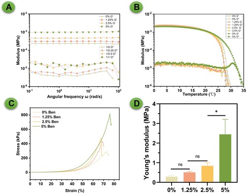
Bentonite's layered structure enhances GelMA's matrix interactions, increasing viscoelasticity, which improves bioink printability and the scaffold's structural integrity. Furthermore, Bentonite's cation exchange capacity strengthens mechanical stability by promoting cross-linking in GelMA. As a type of inorganic microparticle, Bentonite also raises the hydrogel network's stiffness and strength through physical cross-linking, leading to better stress distribution and improved mechanical properties, crucial for durable, functional tissue engineering scaffolds. The strain sweep tests for GelMA/Bentonite scaffolds indicate an increase in strain threshold before mechanical failure as Bentonite content rises (C). Notably, the 5% Bentonite scaffold demonstrates enhanced deformability, suggesting improved ductility and toughness. This is reflected in the significant rise in Young's Modulus to 2.4 MPa for the 5% Bentonite composition, signalling a stiffer scaffold (D). Moreover, the maximum load the scaffolds can bear also increases with higher Bentonite concentrations (Figure S1). Although the mechanical support provided by the 5% Bentonite scaffold is not sufficient for load-bearing areas, it is sufficient for applications in non-load-bearing areas. As the scaffold gradually mineralises and bone repair progresses, the bone defect area will eventually achieve the mechanical strength of natural bone tissue. The study reveals that Bentonite incorporation substantively benefits the mechanical and rheological properties of GelMA scaffolds, with the 5% concentration offering a promising balance of elasticity and stiffness for bone tissue engineering applications. It is well known that due to high water content, the mechanical properties of hydrogel-based materials generally do not match those of natural bone. Although the 2.4 MPa Young's modulus of the 5% Bentonite composition is significantly higher than that of the pure GelMA group, it is still far below the typical stiffness of natural bone tissue, which is usually in the GPa range. However, it is important to emphasise that the application of hydrogel scaffolds in bone tissue engineering, especially in our study, is primarily aimed at non-load-bearing bone defects, such as cranial defects. In these cases, the mechanical requirements are much less stringent than those for load-bearing areas. For defects in load-bearing areas, the use of additional supportive materials (such as metal plates) to provide the necessary mechanical stability is indeed a common practice. Moreover, while initial mechanical limitations exist, the significant advantages of hydrogels, including excellent biocompatibility and high cell activity, should not be overlooked. These characteristics are crucial for promoting cell proliferation and differentiation, which are vital to the bone regeneration process. Additionally, we hypothesise that the in vivo mineralisation process will lead to an enhancement of the mechanical properties of hydrogel scaffolds over time. This process, to some extent, mimics the natural bone healing process, where regenerating bone gradually recovers its mechanical strength. Therefore, while acknowledging the current limitations in mechanical strength, we believe our hydrogel scaffolds hold good potential for application in the non-load-bearing domain of bone tissue engineering. Further studies on their in vivo performance and the evolution of mechanical properties post-implantation are necessary to fully validate their applicability and efficacy in bone regeneration.
3.3. 3d printing properties of the bioinks
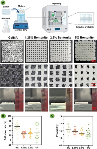
The properties of the 3D printed scaffolds reflect the behaviour of the composite bioinks, which vary with the concentration of bentonite incorporated (). The GelMA/Bentonite hydrogel was thoroughly and uniformly mixed, and then printed into standard shapes using an extrusion-based 3D bioprinter for computation (A). The pristine GelMA scaffold exhibited a relatively transparent appearance and a less defined structure, indicating potential issues with structural integrity [Citation44]. However, the introduction of bentonite at 1.25% and 2.5% concentrations resulted in scaffolds with a whiter hue and a more robust, clearer structure. We have included cross-sectional images to visually demonstrate the thickness of our constructs. Despite identical printing parameters, the addition of Bentonite helps maintain the height of the printed body compared to the pure GelMA group. Furthermore, we have included a video of our 3D printing process. This video not only shows the layer-by-layer construction of these structures but also provides a dynamic view of their development, offering more concrete insights into their three-dimensional nature (Video S1). The enhanced structural definition at these concentrations suggests that bentonite contributes positively to the printability and shape fidelity of the scaffolds. At a higher bentonite concentration of 5%, there was a noticeable alteration in the extrusion characteristics. The increased nozzle width, a consequence of the higher bentonite content, led to scaffolds with narrower pores. This could imply that while bentonite improves the scaffold's visibility and structural rigidity, there is a threshold beyond which further addition of bentonite adversely affects the scaffold's architecture, potentially impacting the material's suitability for cell infiltration and tissue integration. Despite these morphological differences, quantitative assessments of the scaffold properties did not show significant differences across the groups, suggesting that the mechanical properties may not be as sensitive to bentonite concentration as the physical appearance is. Nevertheless, the diffusion rate and overall printability were optimised at lower bentonite concentrations (1.25% and 2.5%), which could be ideal for applications requiring precise pore size and geometry (B-C). These findings indicate a nuanced relationship between bentonite concentration and the resulting properties of the scaffolds, highlighting the importance of optimising bioink composition to achieve the desired outcomes for specific tissue engineering applications [Citation45].
Figure 4. Evaluation of extrusion-based 3D printing performance for composite bioinks. (A) Presents digital images of 3D printed scaffolds from different bioink formulations: pure GelMA, and GelMA enhanced with 1.25%, 2.5%, and 5% Bentonite. (B) Diffusion rate for each bioink composition. (C) Printability assessment.
3.4. Morphology of the printed scaffolds
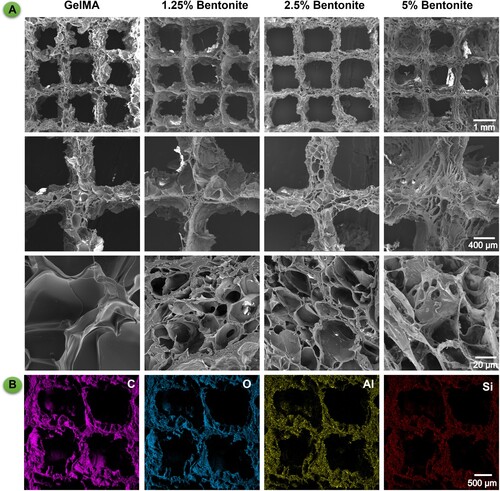
The microarchitecture of the scaffolds, as depicted by SEM, demonstrates a tiered porosity essential for bone tissue engineering (). SEM analysis presents a porous matrix vital for promoting vascularisation and ensuring mechanical interlocking with host tissue [Citation46]. Enhanced magnification reveals a detailed micro-nanoscale landscape, conducive to cellular adherence and growth, thus aligning with the structural complexity of natural bone [Citation47]. The SEM imagery aligns with digital photographs, highlighting that a 2.5% bentonite concentration yields the most defined structural clarity (A). EDS complements these findings by detecting silicon, signifying a scaffold designed for osteoinductivity and bone tissue formation (B). This deliberate silicon integration, as evidenced by the EDS results, suggests the scaffold's capability for sustained ion release, which is instrumental in creating a dynamic biological milieu for bone regeneration. The amalgamation of bioactive components with precise pore architecture significantly bolsters the scaffold's utility, suggesting a viable route for advancing bone tissue engineering endeavours [Citation48].
Figure 5. Microstructure and composition of 3D printed bioink scaffolds. (A) SEM images of 3D printed scaffolds from different bioink formulations: pure GelMA, and GelMA enhanced with 1.25%, 2.5%, and 5% Bentonite. (B) EDS spectra of GelMA/Bentonite scaffolds.
3.5. Biocompatibility properties of the 3D bioprinted scaffolds
The fluorescence microscopy images reveal distinct differences in cell morphology and distribution among the scaffolds (). GelMA/bentonite was combined with BMSCs to create a bio-ink, which was then used in 3D bioprinting to fabricate hydrogel scaffolds. These scaffolds were cultured in vitro, and tests were conducted to assess biocompatibility and cell viability (A). The 2.5% and 5% Bentonite scaffolds exhibit superior cell spreading, with a pronounced network of live cells, as indicated by the extensive green staining (B). This contrast is less evident in the 1.25% Bentonite group, where cell spreading is moderate, and markedly poorer in the pure GelMA group, which shows the least cell distribution and spreading. The CCK-8 assay results correlate with the cell spreading observations. We can infer that the enhanced cell spreading in the 2.5% and 5% Bentonite groups is likely accompanied by higher metabolic activity, a sign of healthy and functioning cells. The pure GelMA group, with its limited cell spreading, may correspond to the lower metabolic activities (C).
Figure 6. Biocompatibility properties of printed scaffolds. (A) Schematic diagram of GelMA/Bentonite 3D bioprinting. (B) The live/dead staining of MSCs cultured on scaffolds demonstrates the biocompatibility of GelMA with varying Bentonite concentrations. (C) OD value from the CCK-8 assay over 7 days indicate cell proliferation rates. (D) Gene expression of ColA1, Runx2, and OPN after 7 days.
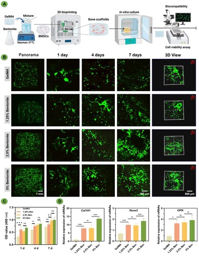
PCR analysis for osteogenic gene expression, including COL1A1, Runx2, and OPN, were measured (D). The 5% Bentonite scaffold exhibited the highest levels of gene expression, correlating with the most favourable cell morphology observed. This outcome suggests that Bentonite content is a key factor in promoting osteogenic differentiation. The 1.25% Bentonite group also displayed notably higher gene expression than the pure GelMA group, reinforcing the concept that even lower concentrations of Bentonite enhance the osteogenic capacity of the scaffolds. These results collectively imply that Bentonite's presence positively influences osteogenic activity, with higher concentrations yielding more pronounced effects.
3.6. Mineralisation of 3D bioprinted scaffolds
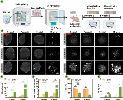
The micro-CT scans captured at the two-week post-implantation mark revealed minimal mineralisation across all scaffold groups (). After three days of in vitro culture, the hydrogel scaffolds created through 3D bioprinting were implanted subcutaneously in nude mice (A). Mineralisation tests were conducted at different time points. At four weeks, however, there was a noticeable increase in mineralisation, particularly in the scaffolds with a 5% bentonite concentration, suggesting a significant enhancement in material mineralisation. This mineralisation trend is underscored by both the elapsed time and the increased bentonite concentration, indicating a relationship where both factors are influential. The degradation pattern observed in the higher concentration samples implies that an abundance of inorganic components, including silicon and magnesium, may expedite the mineral process (B). Analyzing the statistical data, there is a clear trend where both the concentration of bentonite and the passage of time correlate with an increase in mineral density (C) and total mineral volume (D). Additionally, statistical analysis showed that with the increase in bentonite concentration, particularly when the concentration reached 5%, there was a significant decrease in trabecular separation (Tb.Sp) value (E) and a significant increase in trabecular number (Tb.N) value (F). This confirmed the superior self-mineralisation and osteogenic capabilities of the 5% bentonite printed scaffolds. These findings suggest that adjusting the concentration of bentonite within the bioink formulations could serve as an effective means to modulate not only the mineralisation kinetics but also the mechanical attributes of the scaffolds, offering a customisable approach to scaffold fabrication for bone tissue engineering applications.
Figure 7. In vivo mineralisation of bioprinted scaffolds subcutaneous culture in nude mice over time. (A) Schematic diagram of GelMA/Bentonite mineralisation research. (B) μCT reconstructions demonstrating the progressive mineralisation of bioprinted scaffolds after 2 and 4 weeks of in vivo cultivation. (C) Mineral density. (D) Total mineral volume. (E) Trabecular separation. (F) Trabecular number.
3.7. Enhancement of BMSCs osteogenic differentiation of 3D bioprinted scaffolds
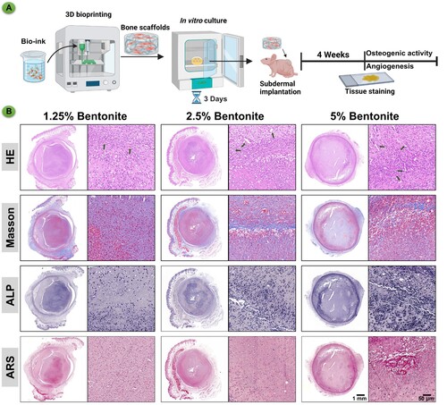
The histological assessment presented in the images showcases the influence of varying concentrations of bentonite within GelMA scaffolds on osteogenic differentiation in vivo (). After culturing the hydrogel scaffolds created by 3D bioprinting in vitro for three days, they were implanted subcutaneously in nude mice. Approximately four weeks later, tests were conducted for angiogenesis and osteogenic activity (A). In the Masson's Trichrome staining, which highlights the collagen fibres in blue, there is a noticeable increase in collagen deposition in the 5% bentonite group, indicative of a more substantial extracellular matrix formation critical for bone strength and structure. The ALP staining, which marks areas of osteogenic activity, reveals a pronounced ALP expression in the 5% bentonite scaffolds, suggesting heightened osteoblast function and a more dynamic bone formation process. This is aligned with the belief that ALP activity is a precursor to mineral deposition in the bone matrix. Alizarin Red S (ARS) staining, specific for calcium deposits, further corroborates the findings of enhanced mineralisation in the 5% bentonite scaffolds. The intense and widespread red staining indicates not only an increase in calcium-rich deposits but also an advanced stage of bone tissue maturation and mineralisation. Collectively, these results elucidate the positive impact of 5% bentonite concentration on the osteogenic differentiation process, promoting increased collagen deposition, osteogenic activity, and mineralisation (B). The 5% bentonite group stands out as the most favourable for bone tissue engineering applications, emphasising the potential of this composite material in enhancing the quality and rate of bone repair. These findings advocate for the utilisation of GelMA/bentonite bioinks, particularly with higher bentonite content, to optimise bone healing outcomes in clinical settings.
Figure 8. Immunohistochemistry of bioprinted scaffolds after subcutaneous culture in nude mice for 4 weeks. (A) Schematic diagram of GelMA/Bentonite for angiogenesis and osteogenesis promotion. (B) HE, Masson's trichrome, ALP, and ARS staining of GelMA/Bentonite scaffolds implanted subcutaneously in nude mice at 4 weeks.
3.8. In vivo bone regeneration assessment
The micro-CT scans present a visual narrative of bone repair in rat cranial defects, with assessments made at 4 and 8 weeks after scaffold implantation (). After culturing the hydrogel scaffolds produced by 3D bioprinting in vitro for three days, they were implanted into the cranial defect areas of rats. The healing of the bone defects was observed at different time points (A). After 4 weeks, the scans reveal early signs of bone tissue development, with certain scaffold formulations fostering greater ingrowth. At the 8-week mark, a pronounced advancement in bone repair is especially evident in the 5% Bentonite group, where there's a significant filling of the defect area with new bone tissue (B). At the 8-week mark, HE and Masson's trichrome staining revealed significant coverage of bony collagen at the defect site in the 5% Bentonite group (C). The quantitative analysis, including bone mineral density (BMD) value (D), bone volume to total volume (BV/TV) value (E), and trabecular number (Tb.N) value (F), corroborates the visual data, showing a consistent increase in these parameters as Bentonite concentration rises. This correlation highlights the 5% Bentonite/GelMA scaffolds’ efficacy, suggesting their enhanced potential for bone regeneration applications. Overall, the scaffolds, particularly those with higher Bentonite content, demonstrate potential for promoting robust bone healing, indicating their suitability for advancing bone tissue engineering and the healing of complex skeletal defects.
Figure 9. Bone regeneration evaluation at 4 and 8 weeks of 3D printed scaffolds by a rat calvarial defect mode in vivo. (A) Schematic diagram of GelMA/Bentonite scaffolds treatment for rat cranial defects. (B) Reconstructed micro-CT scans of the defects in SD rats. (C) Histological staining including HE and Masson's Trichrome staining of calvaria sections. (D) BMD (bone mineral density). (E) BV/TV (bone tissue volume/total tissue volume). (F) Tb. N (Trabecular number). (*P < 0.05, **P < 0.01 and ***P < 0.001).
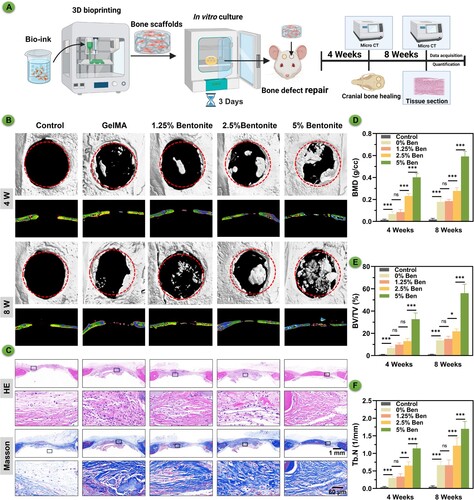
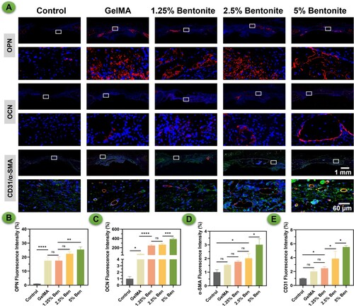
In the provided histological images, various staining techniques reveal the progressive development of bone tissue in response to different concentrations of bentonite within GelMA scaffolds. H&E staining displays the general morphology and cellularity within the scaffold regions, serving as a baseline for comparison with other staining outcomes. Masson's Trichrome, a stain specific for collagen, shows a marked increase in mineralised collagen deposition in scaffolds containing 5% bentonite (B). This increased deposition suggests a more robust matrix formation, which is essential for the structural integrity of new bone. The intensity and distribution of OPN and OCN are noticeably greater in the 5% bentonite group, indicating a concentration-dependent enhancement of osteogenic differentiation. This correlation implies that the inclusion of bentonite not only supports but actively promotes the bone regeneration process. Furthermore, dual immunofluorescence staining for CD31/ α-SMA highlights the vascular structures within the scaffold. The 5% bentonite scaffolds exhibit a denser network of CD31/α-SMA-positive structures, indicating a more favourable environment for angiogenesis. This is crucial for bone healing, as vascularisation is required to supply nutrients and oxygen, crucial for sustaining newly formed tissue (). Overall, these results demonstrate that a higher concentration of bentonite within GelMA scaffolds significantly promotes the deposition of mineralised collagen, expression of osteogenic proteins, and vascular ingrowth. These findings suggest that optimising the concentration of bentonite in the composite can enhance the scaffold's bioactivity and efficacy in bone tissue engineering applications. The 5% bentonite scaffolds, in particular, show promise in creating a conducive environment for bone repair and regeneration, warranting further investigation for clinical use.
Figure 10. Immunofluorescence staining of scaffolds at 8 weeks after scaffolds by a rat calvarial defect mode in vivo. (A) OPN, OCN and CD31/α-SMA staining. (B-E) Quantification of immunofluorescence staining.
3.9. In vivo degradation and cytotoxicity assessment
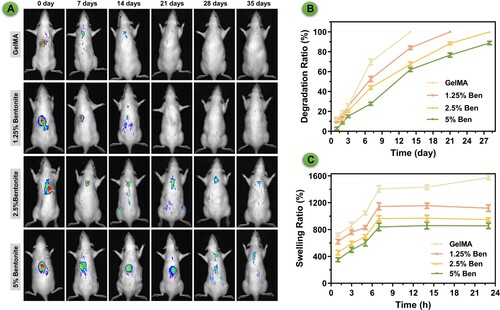
The bioluminescent imaging showcases the differential in vivo degradation behaviours of GelMA and GelMA/Bentonite scaffolds, subcutaneously implanted in rats (). Pure GelMA scaffolds and scaffolds containing 1.25% Bentonite demonstrate a pronounced reduction in luminescence, indicative of rapid degradation. Remarkably, scaffolds with a and 2.5% and 5% Bentonite concentration exhibit a stable bioluminescent signal over time, implying the least degradation among the variants. The apparent inverse relationship between Bentonite content and degradation rate suggests that Bentonite may confer structural reinforcement to the scaffolds, possibly through increased cross-linking or altered interactions with the tissue milieu. The persistent luminescence from the 5% Bentonite scaffolds could indicate a harmonised balance between scaffold breakdown and concurrent tissue regeneration, ideal for maintaining scaffold function during tissue healing. The in vitro degradation of scaffolds showing an accelerated degradation process (B). Despite this difference, the trend remains consistent—scaffolds incorporating Bentonite exhibit slower degradation than those composed of pure GelMA. This slower in vitro degradation is indicative of the stabilising effect Bentonite imparts to the scaffold structure. Swelling measurements underscore the scaffolds’ fluid absorption capability, crucial for internal nutrient distribution and facilitating cellular movement [Citation49]. Scaffolds with higher Bentonite concentrations display a lower degree of swelling (C). These properties are essential for creating a biologically active scaffold conducive to tissue regeneration.
Figure 11. The degradation of scaffolds. (A) Images of in vivo imaging displaying the degradation of bioprinted scaffolds labelled by Sulfo-Cy5.5 NHS ester. (B) Degradation rate in vitro. (C) Swelling ratio in vitro.
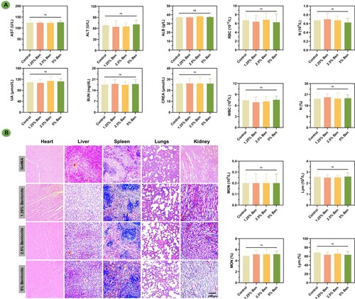
The biocompatibility and biosafety of GelMA and GelMA/Bentonite composite scaffolds have been rigorously evaluated following their subcutaneous implantation into rat cranial defects (). Biochemical assays, including comprehensive blood and platelet counts, have been conducted with meticulous attention to detect any systemic irregularities. The data confidently indicate normalcy across all parameters, suggesting that these scaffold variants maintain physiological homeostasis without eliciting toxic responses. Notably, even as the proportion of bentonite escalates, there is no onset of systemic toxicity, which is a testament to the biocompatible nature of the scaffolds. Histopathological investigations of essential organs reinforce the systemic findings, revealing an absence of detrimental effects on organ tissues. Such histological normality spans the heart, liver, spleen, lungs, and kidneys, with tissues remaining unaffected by the presence of scaffold materials in the body. This suggests a high level of biocompatibility, which is particularly promising for the higher bentonite concentrations that might be expected to have a more pronounced biological impact. The research suggests that GelMA/bentonite scaffolds can be considered non-toxic and safe for in vivo applications, paving the way for their use in clinical settings for bone regeneration.
Figure 12. Assessment of cytotoxicity of bioprinted scaffolds. (A) Blood biochemical indicators. (B) HE staining results of various organs in rats after implantation of scaffolds for 4 weeks.
4. Conclusion
In conclusion, this study has made a pivotal advancement in bone tissue engineering by developing an innovative GelMA/Bentonite composite bioink tailored for 3D bioprinting. The inclusion of Bentonite, with its significant mineral content and ion-exchange properties, has been shown to bolster both the mechanical and biological performance of bioprinted scaffolds, thereby enhancing osteoinduction and promoting tissue regeneration. The ability to integrate Bentonite into GelMA bioinks not only underscores the practicality of this approach but also underlines its transformative potential in advancing scaffold-based bone regeneration techniques. The success of this bioink in fostering cellular adhesion, proliferation, and differentiation signifies a leap forward in bone tissue engineering, potentially diminishing the reliance on traditional grafting methods and opening new avenues for future research and clinical applications.
Supplemental Material
Download PDF (230.9 KB)Disclosure statement
The authors declare that there are no relevant financial or non-financial competing interests in relation to the manuscript submitted for publication. This includes, but is not limited to, employment, consultancies, stock ownership, honoraria, patents or patent applications, and grants or other funding.
Data availability statement
The data that support the findings of this study are available from the corresponding author, J. Su, upon reasonable request.
Additional information
Funding
References
- Feng P, Jia J, Peng S, et al. Graphene oxide-driven interfacial coupling in laser 3D printed PEEK/PVA scaffolds for bone regeneration. Virtual Phys Prototyp. 2020;15(2):211–226. doi:10.1080/17452759.2020.1719457
- Yang Y, Ling C, Li Y, et al. Microstructure development and biodegradation behavior of additively manufactured Mg-Zn-Gd alloy with LPSO structure. J Mater Sci Technol. 2023;144:1–14. doi:10.1016/j.jmst.2022.09.059
- Wang J, Li X, Wang S, et al. Bone-targeted exosomes: strategies and applications. Adv Healthcare Mater. 2023;12(18):e2203361. doi:10.1002/adhm.202203361
- Zhang H, Wu S, Chen W, et al. Bone/cartilage targeted hydrogel: strategies and applications. Bioact Mater. 2023;23:156–169.
- Ling C, Li Q, Zhang Z, et al. Influence of heat treatment on microstructure, mechanical and corrosion behavior of WE43 alloy fabricated by laser-beam powder bed fusion. Int J Extreme Manuf. 2024;6(1):015001. doi:10.1088/2631-7990/acfad5
- Huang Y, Zhou Z, Hu Y, et al. Modified mannan for 3D bioprinting: a potential novel bioink for tissue engineering. Biomed Mater. 2021;16(5):055015. doi:10.1088/1748-605X/ac1ab4
- Engel N, Fechner C, Voges A, et al. An optimized 3D-printed perfusion bioreactor for homogeneous cell seeding in bone substitute scaffolds for future chairside applications. Sci Rep. 2021;11(1):22228. doi:10.1038/s41598-021-01516-8
- Liu H, Zhou H, Lan H, et al. Organ regeneration: integration application of cell encapsulation and 3D bioprinting. Virtual Phys Prototyp. 2017;12(4):279–289. doi:10.1080/17452759.2017.1338065
- Wu Y, Li M, Su H, et al. Up-to-date progress in bioprinting of bone tissue. Int J Bioprint. 2022;9(1):628. doi:10.18063/ijb.v9i1.628
- Maresca JA, DeMel DC, Wagner GA, et al. Three-Dimensional bioprinting applications for bone tissue engineering. Cells. 2023;12(9)1230. doi:10.3390/cells12091230
- Zhang Y, Li G, Wang J, et al. Small joint organoids 3D bioprinting: construction strategy and application. Small (Weinheim an der Bergstrasse, Germany). 2024;20(8):e2302506. doi:10.1002/smll.202302506
- Ji S, Guvendiren M. Recent advances in bioink design for 3d bioprinting of tissues and organs. Front Bioeng Biotechnol. 2017;5:23. doi:10.3389/fbioe.2017.00023
- Sakr MA, Sakthivel K, Hossain T, et al. Recent trends in gelatin methacryloyl nanocomposite hydrogels for tissue engineering. J Biomed Mater Res A. 2022;110(3):708–724. doi:10.1002/jbm.a.37310
- Wang X, Jiang J, Yuan C, et al. 3D bioprinting of GelMA with enhanced extrusion printability through coupling sacrificial carrageenan. Biomater Sci. 2024;12(3):738–747. doi:10.1039/d3bm01489d
- Ren X, Wang J, Wu Y, et al. One-pot synthesis of hydroxyapatite hybrid bioinks for digital light processing 3D printing in bone regeneration. J Mater Sci Technol. 2024;188:84–97. doi:10.1016/j.jmst.2024.01.001
- Shuai C, Zan J, Deng F, et al. Core–shell-structured ZIF-8@PDA-HA with controllable zinc ion release and superior bioactivity for improving a poly-l-lactic acid scaffold. ACS Sustain Chem Eng. 2021;9(4):1814–1825. doi:10.1021/acssuschemeng.0c08009
- Zhu W, Li C, Yao M, et al. Advances in osseointegration of biomimetic mineralized collagen and inorganic metal elements of natural bone for bone repair. Regen Biomater. 2023;10:rbad030. doi:10.1093/rb/rbad030
- Abdul Halim NA, Hussein MZ, Kandar MK. Nanomaterials-upconverted hydroxyapatite for bone tissue engineering and a platform for drug delivery. Int J Nanomed. 2021;16:6477–6496. doi:10.2147/IJN.S298936
- Fu J-N, Wang X, Yang M, et al. Scaffold-Based tissue engineering strategies for osteochondral repair. Front Bioeng Biotechnol. 2022;9:812383. doi:10.3389/fbioe.2021.812383
- Cui ZK, Kim S, Baljon JJ, et al. Microporous methacrylated glycol chitosan-montmorillonite nanocomposite hydrogel for bone tissue engineering. Nat Commun. 2019;10(1):3523. doi:10.1038/s41467-019-11511-3
- Kali A, Loulidi I, Amar A, et al. (2021). Exploitation of bentonite for wastewater treatment.
- Lv A, Lv X, Xu X, et al. Tailored ultra-tough, antimicrobial and recyclable hydrogels based on chitosan and ionic liquid modified montmorillonite with different chain lengths for efficient adsorption of organic dyes in wastewater. Int J Biol Macromol. 2024;257(Pt 2):128752. doi:10.1016/j.ijbiomac.2023.128752
- Yoshikawa E, Yokoyama S, Watanabe Y. Separation and purification of montmorillonite from raw bentonite using a simple hydrothermal treatment. Chem Lett. 2023;52(3):132–135. doi:10.1246/cl.220499
- Li D, Li P, Xu Y, et al. Progress in montmorillonite functionalized artificial bone scaffolds: intercalation and interlocking, nanoenhancement, and controlled drug release. J Nanomater. 2022;2022(4):1-20. doi:10.1155/2022/7900382
- Srasra E, Bekri-Abbes I. Bentonite clays for therapeutic purposes and biomaterial design. Curr Pharm Des. 2020;26(6):642–649. doi:10.2174/1381612826666200203144034
- Maisanaba S, Pichardo S, Puerto M, et al. Toxicological evaluation of clay minerals and derived nanocomposites: a review. Environ Res. 2015;138:233–254. doi:10.1016/j.envres.2014.12.024
- Tavares MT, Gaspar VM, Monteiro MV, et al. GelMA/bioactive silica nanocomposite bioinks for stem cell osteogenic differentiation. Biofabrication. 2021;13(3):10. doi:10.1088/1758-5090/abdc86
- Yi H, Ur Rehman F, Zhao C, et al. Recent advances in nano scaffolds for bone repair. Bone Res. 2016;4:16050. doi:10.1038/boneres.2016.50
- Novelli G. Bentonite: an industrial mineral at man kind service. Ann Chim. 2003;93(1–2):129–136.
- Pedroza-González SC, Rodriguez-Salvador M, Pérez-Benítez BE, et al. Bioinks for 3D bioprinting: a scientometric analysis of two decades of progress. Int J Bioprinting. 2021;7(2):333.
- Maxim LD, Niebo R, McConnell EE. Bentonite toxicology and epidemiology - a review. Inhalation Toxicol. 2016;28(13):591–617. doi:10.1080/08958378.2016.1240727
- Caliari SR, Burdick JA. A practical guide to hydrogels for cell culture. Nat Methods. 2016;13(5):405–414. doi:10.1038/nmeth.3839
- Shen C, Wang J, Li G, et al. Boosting cartilage repair with silk fibroin-DNA hydrogel-based cartilage organoid precursor. Bioact Mater. 2024;35:429–444.
- Dutta SD, Bin J, Ganguly K, et al. Electromagnetic field-assisted cell-laden 3D printed poloxamer-407 hydrogel for enhanced osteogenesis. RSC Adv. 2021;11(33):20342–20354. doi:10.1039/D1RA01143J
- Choi YH, Yeo YH, Lee D, et al. 3D bioprinting of cell-laden thermosensitive methylcellulose/nanosilicate composite hydrogels. Cellulose. 2023;30(8):5093-5112. doi:10.1007/s10570-023-05209-5
- Zhang J, Griesbach J, Ganeyev M, et al. Long-term mechanical loading is required for the formation of 3D bioprinted functional osteocyte bone organoids. Biofabrication. 2022;14(3):035018. doi:10.1088/1758-5090/ac73b9
- Meng F, Wang G, Zhou F, et al. Exosomes from young plasma alleviate osteoporosis through miR-217-5p-regulated osteogenesis of bone marrow mesenchymal stem cell. Compos Part B-Eng. 2024;276:111358. doi:10.1016/j.compositesb.2024.111358
- Raptopoulos M, Fischer NG, Aparicio C. Implant surface physicochemistry affects keratinocyte hemidesmosome formation. J Biomed Mater Res A. 2023;111(7):1021–1030. doi:10.1002/jbm.a.37486
- Zhou Y, Damasceno PF, Somashekar BS, et al. Unusual multiscale mechanics of biomimetic nanoparticle hydrogels. Nat Commun. 2018;9(1):181. doi:10.1038/s41467-017-02579-w
- Cao H, Duan L, Zhang Y, et al. Current hydrogel advances in physicochemical and biological response-driven biomedical application diversity. Sig Transd Target Ther. 2021;6(1):426. doi:10.1038/s41392-021-00830-x
- Williams AH, Roh S, Jacob AR, et al. Printable homocomposite hydrogels with synergistically reinforced molecular-colloidal networks. Nat Commun. 2021;12(1):2834. doi:10.1038/s41467-021-23098-9
- Wang J, Guo M. Thermo-responsive, mechanically robust and 3D printable supramolecular hydrogels. Polym Chem. 2022;13(12):1695–1704. doi:10.1039/D2PY00127F
- Vejjasilpa K, Maqsood I, Schulz-Siegmund M, et al. Adjustable thermo-responsive, cell-adhesive tissue engineering scaffolds for cell stimulation through periodic changes in culture temperature. Int J Mol Sci. 2022;24(1):572. doi:10.3390/ijms24010572
- Gan X, Li C, Sun J, et al. GelMA/κ-carrageenan double-network hydrogels with superior mechanics and biocompatibility. RSC Adv. 2023;13(3):1558–1566. doi:10.1039/D2RA06101E
- Freeman S, Calabro S, Williams R, et al. Bioink formulation and machine learning-empowered bioprinting optimization. Front Bioeng Biotechnol. 2022;10:913579. doi:10.3389/fbioe.2022.913579
- Xia P, Luo Y. Vascularization in tissue engineering: the architecture cues of pores in scaffolds. J Biomed Mater Res B. 2022;110(5):1206–1214. doi:10.1002/jbm.b.34979
- Han Y, Cao L, Li G, et al. Harnessing nucleic acids nanotechnology for bone/cartilage regeneration, Small (Weinheim an der Bergstrasse, Germany). 2023;19(37):e2301996. doi:10.1002/smll.202301996
- Wu R, Li Y, Shen M, et al. Bone tissue regeneration: the role of finely tuned pore architecture of bioactive scaffolds before clinical translation. Bioact Mater. 2021;6(5):1242–1254.
- Hao S, Wang M, Yin Z, et al. Microenvironment-targeted strategy steers advanced bone regeneration, materials today. Bio. 2023;22:100741.