
ABSTRACT
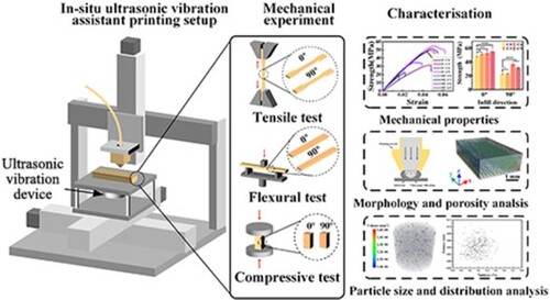
3D-printed HA-PLA composites have attracted much attention because of their excellent biodegradability and osteointegration properties. However, HA particles negatively affect the mechanical properties of the composite parts. In this study, ultrasonic vibration-assisted 3D printing was used to improve the mechanical properties of HA-PLA composite specimens, and the effects of different infill angles and ultrasonic vibration power on the mechanical properties were investigated. The results demonstrated that the degradation and anisotropy of the mechanical properties of HA-PLA composites were alleviated by the use of ultrasonic vibration. By applying the ultrasonic vibration, the tensile and flexural strengths of the 20 wt% HA-PLA specimens fabricated with a 90° infill angle demonstrated the largest improvement of 104.3% and 112.7%, respectively. The high-frequency ultrasonic vibration waves promoted the spreading and fusion of the extruded materials, thereby reducing overlapping voids within the specimens and improving the interface bonding strength, also facilitated the refinement and dispersibility of the HA particles, which inhibited the formation of stress concentrations within the specimens and ultimately improved the mechanical properties. The printing process developed in this study can also be adapted to other particle (or other reinforcement types) reinforced composite to improve their mechanical performance.
GRAPHICAL ABSTRACT
1. Introduction
Three-dimensional (3D) printing has become an effective method for fabricating biodegradable tissue-engineered scaffolds because of its customisation, precise pore controllability, and functionality integration capabilities [Citation1]. A variety of specific materials, including metals, ceramics, and polymers, as well as different types of 3D printing processes, can be used to fabricate biodegradable bone implants [Citation2–4]. Biopolymer – bioceramic composites have attracted significant attention from scholars, who are eager to use them to construct scaffolds because of the combined good processability and bioactivity characteristics, which stem from the biopolymers and bioceramics, respectively [Citation5]. Polylactic acid (PLA) is a promising biopolymer because it has excellent biocompatibility and biodegradability characteristics [Citation6]. Hydroxyapatite (HA) is a widely used bioactive and osteoconductive material that has a chemical composition similar to the inorganic component of natural bone [Citation7]. It is often blended with biopolymers (such as PLA [Citation8–10], polycaprolactone (PCL) [Citation11–13], and polyetheretherketone (PEEK) [Citation14,Citation15]) to enhance the biological activity and osteointegration of the material.
Laser powder bed fusion (LPBF) and fused filament fabrication (FFF) are two of the primary 3D printing processes used to fabricate biopolymer – bioceramic composites [Citation16,Citation17]. FFF has been widely applied because it is inexpensive, effective, and convenient. However, the static mechanical properties of the FFF-fabricated particle-reinforced polymer composite decreased with the increase of reinforced particle content [Citation18,Citation19]. For example, Zhang et al. [Citation20] prepared PLLA/HA scaffolds with HA contents of 0%, 30%, and 50%, their compressive strengths were 45, 30, and 15 MPa, respectively. Wang et al. [Citation21] found that with the n-HA content increase from 0% to 50%, the compressive strengths of the fabricated PLA/n-HA scaffolds decreased gradually. Zheng et al. [Citation22] investigated the tensile strengths of the 0 wt%−30 wt% HA-PEEK specimens. when the HA content increased to 30 wt%, the tensile strength decreased by 48.2% compared with pure PEEK specimens. Several potential causes exist for the printing of composites reinforced by high-content reinforcement phases that have poor mechanical performance. In the FFF process, the reinforcement phase added within the polymer matrix increases the viscosity of the polymer-based composite, which further decreases the extruded line width and increases the size of overlapping voids between adjacent lines. The reduced densification of the printed parts leads to inferior mechanical properties [Citation23]. Additionally, the agglomeration and inhomogeneous distribution of the reinforced particles within the printed parts result in stress concentrations, which further cause pre-failure of the printed parts [Citation13]. Furthermore, the bonding interface between the polymer matrix and reinforcement particles is poor because the two have different material characteristics; thus, printed parts with inferior mechanical properties are produced [Citation24].
There are strategies that can be used to enhance the mechanical properties of 3D-printed particle-reinforced polymer composite parts [Citation25]. These strategies primarily focus on improving the mechanical performance of the parts by reducing the porosity and enhancing the interface bonding strength. By optimising the printing parameters, such as the printing temperature, the printing speed, the printing space, and the layer thickness, the internal overlapping pores within the printed parts can be reduced and the tensile and flexural strengths can be improved [Citation23]. Chemical and physical modifications of the reinforcing filler surfaces are commonly used to improve the bonding strength between the matrix and the particles [Citation26,Citation27]. However, this process is complex and inefficient. The use of post-processing methods, such as annealing [Citation28–30] and laser polishing [Citation31–33], is another way to improve the mechanical properties of printed composite parts [Citation34]. The mechanisms by which these post-treatment strategies improve the mechanical properties of FFF printed parts are related to a reduction of the internal porosity and improvement of the interlayer – inter-raster bonding interface. Part deformation and losses in the dimensional accuracy may occur during post-processing. Energy field-assisted printing strategies to improve the mechanical properties of printed parts are also applied; these sources include external pressures, heat sources, and ultrasonic vibration. The mechanical pressing method integrates the roller and nozzle functions in that the roller exerts pressure on the deposition line extruded from the nozzle during the printing process [Citation35]. Both the temperature of the material extruded from the nozzle and the ambient temperature impact the bonding quality of the deposition lines and layers. Therefore, external heating sources, such as laser [Citation36], infrared [Citation37,Citation38], hot air [Citation39], nozzle-integrated heating [Citation40,Citation41], and microwave heating sources [Citation42], can also be used to increase the temperature of the printing process, thereby improving the quality of the deposition line and interlayer bonding. Ultrasonic strengthen post-treatment and in-situ ultrasonic vibration assistant printing have also been utilised for the FFF process to improve printed parts’ mechanical properties. Ultrasonic strengthen post-treatment which applies pressure and ultrasonic power on the fabricated specimens, has been used to improve the tensile, flexural, and dynamic mechanical properties of the printed PLA and acrylonitrile butadiene styrene (ABS) parts [Citation43–45]. A few studies have also explored the in-situ ultrasonic vibration assistant FFF process. Wu et al. [Citation46] developed an ultrasonic-vibration-assisted FFF device and found the tensile and flexural properties of the PLA specimens were enhanced by using ultrasonic vibration. Maidin et al. [Citation47] clamped the ultrasonic piezoelectric transducer horizontally on the surface of the 3D printer platform and investigated the effect of vibration frequency and build orientation on the compressive properties of the ABS and PLA specimens. Tofangchi et al. [Citation48] connected the ultrasonic transducer to the heater block and studied the effect of ultrasonic vibration on the interlayer adhesion of the ABS specimens. Zhang et al. [Citation49] investigated the effect of ultrasonic-assisted FFF printing on the interface bonding strength between continuous fibre and polymers. These studies focus on reducing the porosity within the printed pure polymer specimens to enhance their mechanical properties and improve the interfacial adhesion strength. However, the effect of ultrasonic power on the anisotropic mechanical properties of the particle-reinforced polymer composite fabricated by different infill angles has not been investigated. Moreover, the effect of ultrasonic vibration on the size and dispersibility of the reinforced particles has not been investigated.
In this study, an in-situ ultrasound-assisted 3D printing method was proposed to improve the mechanical performance of the particle-reinforced-polymer composite. Three HA-PLA filament types with different HA proportions were used to prepare specimens with different infill angles for further static mechanical experiments. The effect of the ultrasonic power on the anisotropic mechanical properties of the HA-PLA composite parts was investigated. The mechanical performance improvement mechanism behind the ultrasonic vibration assistance printing process has also been studied.
2. Materials and methods
2.1. Materials and experimental setup
2.1.1. Materials
Pure PLA, 10 wt% HA-PLA, and 20 wt% HA-PLA filaments with diameters of 1.75 mm (Shaanxi Jugao-AM Medical Technology Co., Ltd.) were used in the experiments. Before the experiments, all the filaments were stored in a dry box for further use.
2.1.2. Experimental setup
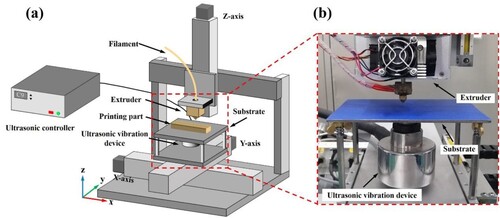
shows the 3D printer developed during this study. The motion parts of the printer consisted of three fully closed-loop linear motion modules with a resolution of 0.01 mm. A extruder was mounted on the Z-axis of the printer to deposit materials. The upper surface of the substrate was the starting surface for the printing process. An ultrasonic vibration device was installed on the bottom surface of the substrate. The ultrasonic frequency of the device was 37 kHz. The ultrasonic power could be adjusted and controlled by an ultrasonic controller.
Figure 1. 3D printer with an ultrasonic vibration device that was developed during this study: (a) schematic diagram of the 3D printer and (b) installation position of the ultrasonic vibration device.
2.2. Specimen fabrication
Tensile specimens (type 1BA), flexural specimens, and compression specimens were designed according to the ISO 527-2:2012 standard, the ISO 178:2019 standard, and the ISO 604:2002 standard, respectively, for the mechanical properties’ tests. The schematics and dimensions of the specimens are shown in (a). All the specimens were placed horizontally, and the deposition direction was along the Z-direction.
Figure 2. Schematic diagrams of the specimens: (a) tensile, flexural, and compression specimen dimensions, (b) tensile experiment, (c) flexural experiment, and (d) compression experiment.
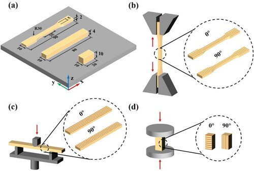
Three filament types with different HA contents were used to fabricate the specimens. To investigate the effect of the ultrasonic power on the mechanical properties of the specimens, four different ultrasonic powers (0, 30, 60, and 90 W) were used to fabricate specimens. Meanwhile, to compare the effect of ultrasonic vibration-assisted printing on the mechanical properties of the specimens produced by the different infill directions, 0° and 90° infill angles were used. The infill direction along the X-direction was defined as the 0° infill angles, and the infill direction along the Y-direction was defined as the 90° infill angles.
A nozzle diameter of 0.4 mm, a printing temperature of 210°C, a printing speed of 40 mm/s, a layer thickness of 0.2 mm, an infill pattern of linear, and an infill density of 100% were set as the basic printing parameters for all the specimens. The printing paths of the specimens (Gcode files) were obtained by slicing the models by Cura 3.6.0. For each configuration, three specimens (n = 3) were fabricated for the mechanical properties tests to ensure the repeatability and reliability of the experiments. The specimens printed with different ultrasonic powers show good dimensional accuracy retention.
2.3. Mechanical experiments
Mechanical tests were conducted by using an electronic universal mechanical testing machine (MTS E44.304) from MTS Test Instruments Corporation (USA). The tensile and flexural tests were conducted with a load cell of 5 kN, while the compression tests were performed with a load cell of 30 kN. The tensile, flexural, and compression speeds were all set to 2 mm/min, according to the standard. Schematic diagrams of the tension, flexural, and compression tests are shown in (b)–(d).
2.4. Fabrication process monitoring
A high-speed camera (FASTCAM NOVA S16, Photron, Japan) with micro-lens (12X Ultra Zoom) was used to observe the molten filament extrusion from the nozzle during the specimen printing process. The frame rate of the camera was set to 4,000 fps.
2.5. Detection of the internal morphologies and micro-structures of the specimens
The middle portions of the tensile specimens were chosen for cross-sectional morphology observations of the as-fabricated specimens. The specimens were immersed in liquid nitrogen for 3 min, after which they were removed and quickly broken. The broken specimens were then sprayed with gold, and their fracture surfaces were observed using a field emission scanning electron microscope (FESEM, JSM-7610Plus, Japan).
A micro-X-ray 3D imaging system (YXLON Cheetah, Germany) was also used to detect internal defects within the specimens. The middle portions of the tensile specimens were used during this non-destructive testing. The XYZ scanning resolution was set to 3 μm, and the peak tube potential was set to 80 kV.
High-resolution, non-destructive X-ray testing equipment (Xradia 515 Versa, ZEISS, Germany) was also used to analyze the HA particle distributions within the HA-PLA composite specimens. A voltage of 100 kV, a power of 9 W, a current of 90 μA, and an XYZ pixel resolution of 0.7813 μm were set as the basic measurement parameters.
3. Results and discussion
3.1. Mechanical properties
3.1.1. Tensile properties
presents the results of the tensile experiments. The ultrasonic vibration power significantly impacted the tensile properties of the specimens. (a) shows the strain – stress curves and tensile strength results for the pure PLA materials fabricated with 0° and 90° infill angles. The tensile strength of the PLA material fabricated with the 0° infill angle increased with increases in the ultrasonic vibration power. The tensile strength increased from 48.30 ± 1.66 MPa to 55.40 ± 0.78 MPa (which represents a 14.7% improvement) when the ultrasonic vibration power increased from 0 W to 90 W. However, the tensile strength of the PLA material fabricated with the 90° infill angle first increased and then decreased slightly as the ultrasonic vibration power increased. The highest tensile strength for this infill direction, 37.11 ± 1.81 MPa, was achieved when the ultrasonic vibration power was 60 W. This result represents a tensile strength enhancement of 60.7% from that obtained with no ultrasonic vibration assistance (0 W). The specimens fabricated with a 90° infill angle had greater tensile strength improvements than those fabricated with a 0° infill angle.
Figure 3. Tensile strength results for specimens fabricated with 0° and 90° infill angles: (a) pure PLA, (b) 10 wt% HA-PLA, and (c) 20 wt% HA-PLA. (‘ns’ indicates no significance; *p < 0.05; ***p < 0.001; ****p < 0.0001).
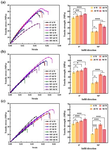
The 10 and 20 wt% HA-PLA specimens fabricated with 0° and 90° infill angles and various ultrasonic vibration powers exhibited similar trends as the pure PLA specimens. The tensile strength of the specimens fabricated with a 0° infill angle increased with increases in the ultrasonic power. For the specimens fabricated with a 90° infill angle, the tensile strength first increased and then decreased when the ultrasonic power increased from 0 W to 90 W. (b) shows that, when the ultrasonic vibration power increased from 0 W to 90 W, the tensile strength of the 10 wt% HA-PLA specimens fabricated with a 0° infill angle increased from 38.32 ± 1.81 MPa to 46.24 ± 0.60, which is a 20.7% enhancement. These tensile properties are comparable to those of pure PLA-printed specimens with no ultrasonic vibration assistance. When an ultrasonic vibration power of 60 W was applied to the 10 wt% HA-PLA specimens fabricated with a 90° infill angle, the highest tensile strength, 34.56 ± 1.32 MPa, was obtained. This result represents an 84.2% tensile strength enhancement from that obtained with no ultrasonic vibration assistance (0 W). (c) shows the tensile curves and tensile strengths for the 20 wt% HA-PLA specimens. The tensile strengths of the specimens fabricated with 0° and 90° infill angles increased by 24.7% and 104.3%, respectively, when ultrasonic powers of 90 W and 60 W were applied during the printing process.
HA, which is a biologically active material, was added to the PLA matrixes to improve the osteogenic properties of the PLA materials and to neutralise acids produced during the PLA degradation process. However, after the addition of HA particles, the mechanical properties of the resulting HA-PLA composite parts were found to be inferior to those of pure PLA materials. As shown in , when the HA content increased from 0 wt% to 20 wt%, the tensile strengths of the 10 and 20 wt% HA-PLA specimens fabricated with a 0° infill angle decreased by 20.7% and 28.6%, respectively. When an ultrasonic vibration power of 90 W was utilised to print specimens with a 0° infill angle, the tensile strengths of the 10 and 20 wt% HA-PLA specimens reached 46.24 ± 0.60 MPa and 43.03 ± 1.73 MPa, respectively; these values were very close to those of the pure PLA specimens (48.30 ± 1.66 MPa). Similarly, the tensile strengths of the 10 wt% HA-PLA specimens (34.56 ± 1.32 MPa) and the 20 wt% HA-PLA specimens (33.09 ± 1.87 MPa) fabricated with a 90° infill angle even exceeded those of the pure PLA specimens (23.09 ± 1.17 MPa) when the ultrasonic power of 60 W was used.
Table 1. Tensile strength results for different materials.
The printed parts exhibited obvious mechanical anisotropy, which is another problem inherent to the FFF process. 3D-printed specimens have different mechanical properties when they are fabricated with different infill or placement orientations; this phenomenon is called mechanical anisotropy. It occurs because there are different bonding strengths between adjacent printing lines and adjacent layers and because the specimens have different loading characteristics in different directions. The specimens fabricated with a 0° infill angle, which coincides with the sample loading direction, usually had better mechanical properties than the specimens fabricated with a 90° infill angle. The infill direction is one of the factors that affect the mechanical properties of FFF printed parts. When ultrasonic vibration-assisted printing was used, the tensile strength enhancements in the specimens fabricated with a 90° infill angle were greater than those fabricated with a 0° infill angle. The use of the ultrasonic vibration-assisted printing process reduced the mechanical anisotropy of the 3D-printed specimens. The mechanical anisotropy of the specimens decreased from 52.2% to 23.2% for the PLA materials, from 51.0% to 9.8% for the 10 wt% HA-PLA materials, and from 53.1% to 4.1% for the 20 wt% HA-PLA materials when the ultrasonic power of 60 W was used. This result may have occurred because, when ultrasonic vibration was applied, the in-plane vibration waves facilitated the dispersion of the extruded material and increased the bonding strength between neighbouring printed lines under high-frequency friction.
3.1.2. Flexural properties
The flexural curves and flexural strength results for all the specimens are presented in . The flexural strengths of the PLA specimens fabricated with a 0° infill angle increased with an increase in the ultrasonic vibration power. When the ultrasonic vibration power reached 90 W, the flexural strengths of these PLA specimens were enhanced by 9.5%. The flexural strengths of the PLA specimens fabricated with a 90° infill angle also increased with increases in the ultrasonic power. When an ultrasonic vibration power of 90 W was applied, the flexural strengths were 4% greater than those of the specimens fabricated without ultrasonic vibration. However, this strength improvement is not statistically significant.
Figure 4. Flexural strength results for specimens fabricated with 0° and 90° infill angles: (a) pure PLA, (b) 10 wt% HA-PLA, and (c) 20 wt% HA-PLA. (‘ns’ indicates no significance; ***p < 0.001; ****p < 0.0001).
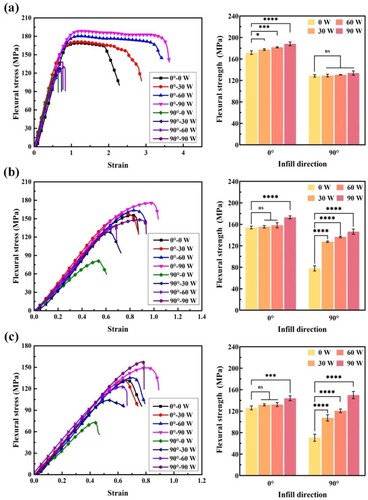
Similar to the pure PLA specimens, the flexural strengths of the 10 wt% HA-PLA specimens fabricated with a 0° infill angle gradually increased as the ultrasonic vibration power increased. Maximum flexural strength of 173.03 ± 2.70 MPa was achieved when an ultrasonic vibration power of 90 W was applied, which represents a 12.3% increase from the value obtained without ultrasonic vibration. Unlike the PLA specimen results, the flexural strengths of the 10 wt% HA-PLA specimens fabricated with a 90° infill angle exhibited significant improvements when ultrasonic vibration was used. The flexural strengths increased from 77.93 ± 4.69 MPa to 127.67 ± 1.46 MPa, 136.57 ± 1.48 MPa, and 146.30 ± 5.03 MPa, respectively, when ultrasonic vibration power of 30 W, 60 W, and 90 W were applied. A maximum enhancement of 87.7% was obtained when the largest ultrasonic power, 90 W, was used.
The flexural strengths of the 20 wt% HA-PLA specimens followed the same trends as those of the 10 wt% HA-PLA specimens. When the ultrasonic power increased to 90 W, the flexural strengths of the 20 wt% HA-PLA specimens fabricated with a 0° infill angle increased from 126.17 ± 3.63 MPa to 143.98 ± 4.48 MPa, which represents a 14.1% improvement. The flexural strength of the 20 wt% HA-PLA material fabricated with a 90° infill angle increased by 112.7% when an ultrasonic vibration power of 90 W was applied.
The flexural strength results for all the specimens are presented in . The application of ultrasonic vibration enhanced the mechanical properties of the HA-PLA composites. When an ultrasonic vibration power of 90 W was applied, the flexural strengths of the 20 wt% HA-PLA specimens fabricated with a 0° infill angle were merely 16.2% lower than those of the pure PLA specimens, while the flexural strengths of the 10 wt% HA-PLA specimens were even greater than those of the pure PLA specimens. Similarly, the flexural strengths of the 10 and 20 wt% HA-PLA specimens fabricated with a 90° infill angle were greater than those of the pure PLA specimens by 13.8% and 16.7%, respectively, when ultrasonic vibration power of 90 W was applied. Another issue regarding the anisotropic mechanical properties of the 3D printed specimens was also mitigated by the application of ultrasonic vibration. The flexural strength results indicate that the flexural strength anisotropy of the pure PLA, 10 wt% HA-PLA, and 20 wt% HA-PLA specimens decreased from 29.3% to 26.4%, from 49.4% to 5.1%, and from 44.1% to −18.9%, respectively, when an ultrasonic vibration power of 90 W was applied to specimens fabricated with a 90° infill angle. The flexural strengths of the 20 wt% HA-PLA specimens fabricated with a 90° infill angle even exceeded those of specimens fabricated with a 0° infill angle when ultrasonic vibration was used.
Table 2. Flexural strength results for the different materials.
3.1.3. Compression properties
The compression strength results for specimens fabricated with 0° and 90° infill angles and various ultrasonic powers are presented in . The results show that the use of ultrasonic vibration positively affected the compression strengths of the specimens. Regardless of whether the specimens were fabricated with a 0° or 90° infill angle, the compression strengths improved when ultrasonic vibration energy was added to the printing process.
Figure 5. Compression strength results for specimens fabricated with 0° and 90° infill angles: (a) PLA, (b) 10 wt% HA-PLA, and (c) 20 wt% HA-PLA. (‘ns’ indicates no significance; *p < 0.05; **p < 0.01; ***p < 0.001; ****p < 0.0001).
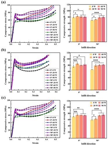
The compression strengths of the PLA specimens fabricated with a 0° infill angle first increased and then decreased as the ultrasonic vibration power increased. However, the compression strengths of the specimens subjected to ultrasonic vibration were all greater than those of the specimens fabricated without ultrasonic vibration assistance. Maximum compression strength of 82.16 ± 0.56 MPa was obtained when an ultrasonic vibration power of 30 W was used, which represents an increase of 4.7% from the strengths of specimens fabricated without ultrasonic vibration (78.44 ± 1.28 MPa). However, different results were obtained for specimens fabricated with a 90° infill angle. The compression strengths of these specimens gradually increased with increases in the ultrasonic power. The specimens exhibited a maximum compression strength of 79.71 ± 2.25 MPa when an ultrasonic vibration power of 90 W was used, which represents a 14.3% increase from that when 0 W was used.
The compression strengths of the 10 wt% HA-PLA specimens had the same tendencies as those of the pure PLA specimens. The specimens fabricated with a 0° infill angle exhibited a maximum compression strength of 84.53 ± 1.90 MPa when an ultrasonic vibration power of 30 W was applied. The specimens fabricated with a 90° infill angle exhibited a maximum compression strength of 81.42 ± 1.00 MPa when 90 W ultrasonic power was used. Thus, the compression strengths of the specimens fabricated with 0° and 90° infill angles improved by 11.5% and 23.6%, respectively, when compared to those of the specimens fabricated without ultrasonic vibration assistance.
Compression strength improvement also occurred for the 20 wt% HA-PLA specimens when ultrasonic vibration was included in the printing process. The specimens fabricated with a 0° infill angle had maximum enhancements of 7.8% when ultrasonic power 30 W was used, and the specimens fabricated with a 90° infill angle had maximum enhancements of 27.3% when ultrasonic power 90 W was used.
summarises the compression strength results for all the specimens. The compression strengths of the specimens decreased as the HA content increased. These results are consistent with those of other studies [Citation18,Citation20]. The compression strength variations between specimens with different amounts of HA and different infill angles were reduced by ultrasonic vibration assistance. Adding the ultrasonic vibration assistance strategy to the printing process significantly enhanced the compression strengths of the specimens with greater amounts of HA, as well as those fabricated with an infill angle of 90°. These improvements reduced the differences between the compression strengths of the pure PLA specimens and the HA-PLA composite specimens. The differences between the compression strengths obtained with different infill orientations simultaneously decreased.
Table 3. Compression strength results for different materials.
compares the tensile, flexural, and compressive strengths of the specimens fabricated before and after using ultrasonic vibration, as well as the results from other literature. The results show that after using the ultrasonic vibration assistant printing process, the tensile, flexural, and compressive strengths of the HA-PLA specimens fabricated with 0° and 90° infill angles all improved. The tensile strength of the pure PLA and HA-PLA specimens obtain by FFF most below 50 MPa and 40 MPa, respectively. However, by applying the ultrasonic vibration, the highest tensile strength of the pure PLA, 10 wt% HA-PLA, and 20 wt% HA-PLA specimens were 55.4 MPa, 46.2 MPa, and 43.03 MPa, respectively. These tensile strength values are within the range of values obtained by injection molding (IM). The flexural strength of the specimens fabricated with ultrasonic vibration in this study exceeds other research results and flexural strength values obtained by IM. Compression strength values obtained in this study are comparable to other research results. The anisotropy mechanical properties of the HA-PLA specimens fabricated with different infill angles were narrowed. Moreover, the mechanical properties degradation of the HA-PLA specimens with the increase of HA content were alleviated.
Figure 6. Comparison of mechanical properties before and after ultrasonic vibration and comparison with other manufacturing processes including FFF and injection molding (IM): (a) tensile strength [Citation50–55], (b) flexural strength [Citation10,Citation23,Citation51,Citation53–55], and (c) compressive strength [Citation9,Citation10,Citation21,Citation56,Citation57]
![Figure 6. Comparison of mechanical properties before and after ultrasonic vibration and comparison with other manufacturing processes including FFF and injection molding (IM): (a) tensile strength [Citation50–55], (b) flexural strength [Citation10,Citation23,Citation51,Citation53–55], and (c) compressive strength [Citation9,Citation10,Citation21,Citation56,Citation57]](/cms/asset/d6ddb14f-5ed9-42a7-98a8-a938c7ba28b9/nvpp_a_2346271_f0006_oc.jpg)
3.2. Morphology and porosity analyses
FFF printing is the process of connecting deposited lines that are extruded from a nozzle to form a deposited layer and then stacking the layers to form a 3D part. Pores, which are formed at the junctions of adjacent deposited lines, are a common issue in the FFF process. The mechanical properties of the 3D-printed parts are highly related to the internal pore characteristics and microstructures of the parts. Generally, 3D-printed parts with high densities and low porosities exhibit better mechanical properties than parts with low densities and high porosities.
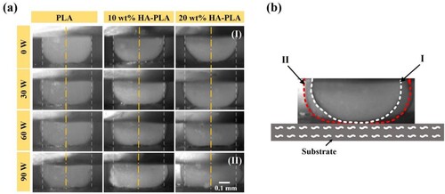
The cross-sectional morphologies of the deposited lines significantly affect the bonding quality between adjacent deposited lines. To investigate the relationship between the morphology of a single deposited line and the ultrasonic vibration power, a high-speed camera with micro-lens was used to monitor the material extrusion process. The extrusion morphologies of single lines fabricated with different ultrasonic powers are shown in (a), which demonstrates that the ultrasonic vibration power significantly affects the morphologies of deposited lines. As the ultrasonic vibration power increased from 0 W to 90 W, the transverse ultrasonic vibration waves caused the material to spread out to both sides. For the 10 wt% HA-PLA and 20 wt% HA-PLA materials in particular, more material adhered to previously printed layers as the ultrasonic vibration power increased. Therefore, the contact area between adjacent printed layers increased, which is beneficial for the bonding quality between the printed layers and the mechanical properties of the printed parts. As shown in (b), comparison between the cross-sectional profile of a single deposition line with ultrasonic vibration-assisted printing (red colour) and the cross-sectional profile of a single deposition line without ultrasonic vibration-assisted printing (white colour). It can be seen that the lower part of the cross-sectional profile of the single deposition lines printed with ultrasonic vibration-assisted printing spreads out more flatly. Flat and rectangular cross-sectional shapes can reduce the porosity of overlapping areas between adjacent deposition lines, as shown in .
Figure 7. Morphologies of single printed lines extruded under various ultrasonic vibration powers: (a) morphologies of single extruded lines captured by a high-speed camera and (b) schematic diagram of the morphologies of single lines extruded with and without ultrasonic vibration assistance.
A micro-X-ray 3D imaging system was used during this study to investigate the internal defects within specimens fabricated with different ultrasonic vibration powers, and the results are presented in . Material extracted from the middle portions of the tensile specimens was used to analyze the porosities of the specimens. The different colours in the figure represent the volume of internal voids within the specimens. As shown in the figure, overlapping voids existed between adjacent deposition lines along the printing direction throughout all the specimens. As the ultrasonic vibration power increased, the volume of internal voids decreased. The calculated porosity results for the specimens are summarised in . The porosities of the pure PLA specimens decreased from 6.60% to 4.93%, which represents a reduction of 25.3%, as the ultrasonic vibration power increased from 0 W to 90 W. Similarly, as the ultrasonic vibration power increased, the porosities of the 10 wt% HA-PLA material decreased from 6.70% to 2.47%, which is a 63.1% reduction, and the porosities of the 20 wt% HA-PLA specimens decreased from 6.90% to 2.94%, which is a reduction of 57.4%.
Figure 8. Internal porosity analysis of specimens fabricated with various ultrasonic powers.
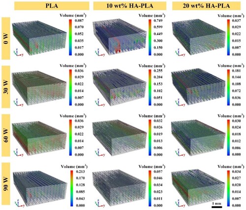
Table 4. Porosity values of specimens fabricated with various ultrasonic vibration powers.
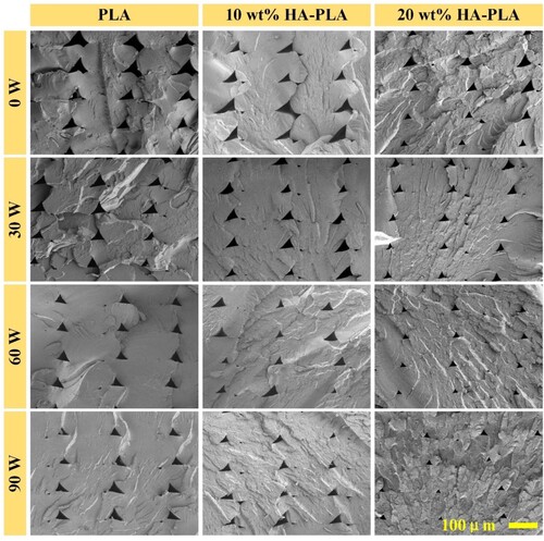
To observe the morphologies of the as-fabricated specimens fabricated with different ultrasonic vibration powers, as well as the interline and interlayer bonding qualities, an FESEM was used to capture the cross-sectional morphologies of the specimens. The results are presented in . The overlapping pores within the specimens were triangular in shape, and they were formed by the line-by-line and layer-by-layer stacking process. The size of overlapping voids within the specimens (especially within the 10 wt% HA-PLA and 20 wt% HA-PLA specimens) decreased as the ultrasonic vibration power increased from 0 W to 90 W. The decreased porosities of the specimens indicated improvements in their densities, which was an important factor in the overall improvement of the specimens’ mechanical properties. Additionally, the contact areas between neighbouring lines and layers also increased with ultrasonic vibration assistance. The bonding strengths of the interlayer interfaces were also enhanced as the ultrasonic vibration power increased. This was especially true for the interlines and interlayer interfaces of the 20 wt% HA-PLA specimens fabricated with an ultrasonic vibration power of 90 W; the interfaces could hardly be identified in these specimens, which indicates that excellent bonding was achieved.
Figure 9. Cross-sectional morphologies of the as-fabricated specimens constructed with various ultrasonic powers.
With the help of ultrasonic vibration, the extruded materials spread out evenly. The overlapping voids between adjacent deposition lines decreased in size and the contact areas between adjacent layers became larger because of the good material dispersion. The reduced porosity positively affected the mechanical properties of the specimens. This is part of the reason for the improvements in the mechanical properties of the specimens when ultrasonic vibration was employed. Meanwhile, it was observed that the porosity reduction was greater for the HA-PLA composite specimens than for the pure PLA specimens. Thus, the tensile, flexural, and compression properties of the HA-PLA composite specimens exhibited greater improvements than the pure PLA specimens when ultrasonic vibration assistance was utilised.
3.3. Dispersion of the reinforced particles
To investigate the sizes and distributions of the HA particles within the specimens, high-resolution, non-destructive X-ray detection was conducted. The distributions and sizes of the HA particles within the 10 wt% HA-PLA and 20 wt% HA-PLA raw filaments, as well as within the 10 wt% HA-PLA and 20 wt% HA-PLA specimens fabricated with and without ultrasonic vibration (at powers of 0 W and 90 W, respectively), were analyzed.
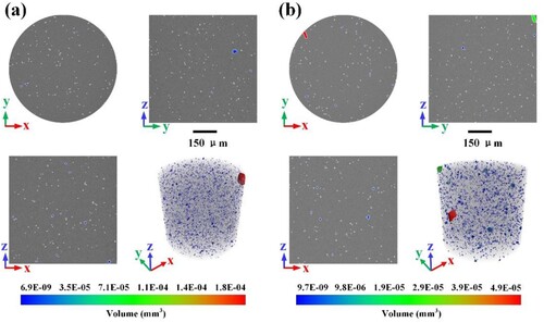
The HA particle sizes and distributions within the 10 wt% HA-PLA and 20 wt% HA-PLA filaments are shown in . The high-density HA particles, which have bright colours in the figure, were extracted from the composite filaments by adjusting the thresholds. The HA particle volume ranges are indicated by different colours, and the position distributions are presented in the 3D rendering models. The figure shows that there were many large particles within the raw filaments. The 20 wt% HA-PLA raw filaments contained more large particles than the 10 wt% HA-PLA raw filaments. These large particles were formed during the filament-preparation and extrusion processes. As the HA particle content increased, the HA-PLA mixture became less homogeneous, and more large HA particles remained within the filaments.
Figure 10. Distributions and sizes of HA particles within the raw filaments: (a) 10 wt% HA-PLA raw filaments and (b) 20 wt% HA-PLA raw filaments.
Large particles within the filaments and inhomogeneous distributions caused the HA-PLA filaments to become brittle and possess poor mechanical properties. The HA-PLA composite 3D-printed parts fabricated from these raw filaments had the same problems. The internal microstructures of the 10 wt% HA-PLA specimens fabricated without ultrasonic vibration assistance are shown in (a). Large HA particles still existed within these specimens; however, the HA particles were smaller than the filaments, and all the exceptionally large particles disappeared. These results may have occurred because of the secondary squeezing between the nozzle and the printing substrate during the printing process. When ultrasonic vibration was used to aid the printing process, the printed parts had few large HA particles, as shown in (b). The ultrasonic vibration helped break the large HA particles into small particles during the printing process.
Figure 11. Distributions and sizes of the HA particles within the HA-PLA specimens: (a) 10 wt% HA-PLA specimen fabricated without ultrasonic vibration (0 W), (b) 10 wt% HA-PLA specimen fabricated with ultrasonic vibration (90 W), (c) 20 wt% HA-PLA specimen fabricated without ultrasonic vibration (0 W), and (d) 20 wt% HA-PLA specimen fabricated with ultrasonic vibration (90 W).
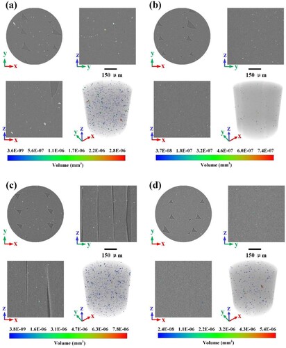
The microstructures of the 20 wt% HA-PLA composite specimens are shown in (c,d). There were more HA particles within the 20 wt% HA-PLA specimens than within the 10 wt% HA-PLA specimens. The specimens fabricated with ultrasonic vibration assistance had fewer large HA particles than the specimens fabricated without ultrasonic vibration.
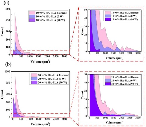
The volume ranges and counts of HA particles are shown in (a) for the 10 wt% HA-PLA filaments and specimens. The HA particles within the 10 wt% HA-PLA filaments had a large range of volumes, and there were some especially large particles, the same as the rendered 3D model shown (). When an ultrasonic vibration power of 90 W was used during the specimen printing, the HA particle volume distribution was narrowed. The ultrasonic vibration promoted the fragmentation of large HA particles into smaller particles. The total number of HA particles within the specimens fabricated with ultrasonic vibration assistant was also reduced. This result may have occurred because the resolution of the detection equipment was not high enough to detect the smaller HA particles, which were thus difficult to capture and extract. The number and volume distribution of the HA particles within the 20 wt% HA-PLA raw filaments and specimens followed the same trends as those of the 10 wt% HA-PLA samples, as shown in (b). The 20 wt% HA-PLA specimens had more HA particles than the 10 wt% HA-PLA specimens regardless of whether or not ultrasonic vibration was used because of the high HA content of the 20 wt% HA-PLA filaments.
Figure 12. Comparison of the number and volume of particles in filaments, without ultrasonic vibration-assisted printing specimens, and ultrasonic-assisted vibration-printed specimens: (a) 10 wt% HA-PLA filaments and specimens and (b) 20 wt% HA-PLA filaments and specimens.
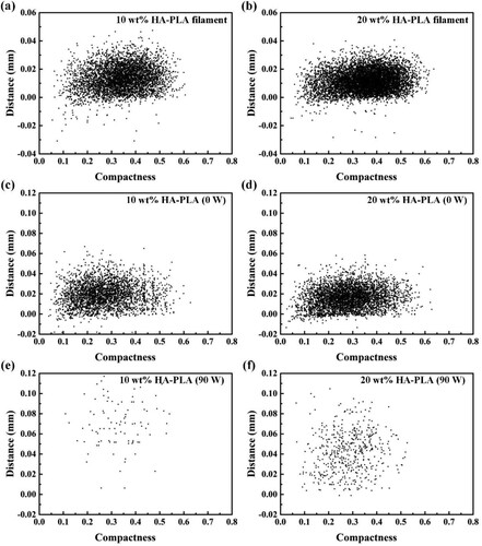
The distributions of HA particles within the 10 wt% HA-PLA and 20 wt% HA-PLA raw filaments and specimens fabricated with ultrasonic vibration powers of 0 W and 90 W are compared in . To calculate the distances between all the HA particles within the specimens, the irregular HA particles were simplified as their circumscribed spheres. The x-coordinates of the plots in indicate compactness, which is the ratio between the volume of a particle and the volume of the corresponding sphere. The y-coordinates indicate distance, which is defined as the minimum gap between the outer surfaces of two spheres. The plots in the figure indicate that the reinforced HA particles within the PLA matrixes were better dispersed when ultrasonic vibration was used during the printing process. For both the 10 and 20 wt% HA-PLA specimens, the distances between the HA particles within the specimens increased when an ultrasonic vibration power of 90 W was applied during the printing process. The ultrasonic vibration also helped the HA particles avoid agglomeration and achieve good dispersibility within the specimens.
Figure 13. Dispersibility of the HA particles within the filaments and specimens fabricated with ultrasonic vibration powers of 0 and 90 W.
The cross-sectional morphologies of the 10 and 20 wt% HA-PLA specimens were captured with high magnification by an FESEM, and the results are presented in . Agglomerated particles and large particles can be seen in the 10 and 20 wt% HA-PLA specimens fabricated without ultrasonic vibration. As the ultrasonic vibration power increased, the HA particles became well dispersed within the PLA matrixes.
Figure 14. Particle distribution analysis for specimens fabricated with various ultrasonic powers.
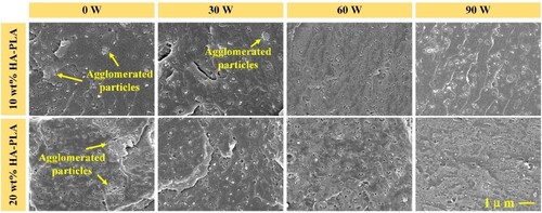
The HA particle dispersibility within the PLA matrixes is another key factor that affects the mechanical performance of HA-PLA composites. Large, agglomerated HA particles within the HA-PLA composites can easily cause stress concentrations when the composite parts are subjected to external loading. This is an important reason for the mechanical property degradation associated with HA-PLA composites. The 10 and 20 wt% HA-PLA raw filament preparation processes generate many large HA particles within the filaments. The sizes of the HA particles within the extruded materials can be reduced slightly by the secondary squeezing that occurs between the printing nozzle and the substrate during the printing process. However, many large HA particles still exist within the HA-PLA specimens, and these particles have poor dispersibility characteristics. High-frequency ultrasonic vibration promotes the squeezing effect; thus, the HA particles within the extruded materials can be broken into smaller particles. In-plane ultrasonic vibration also facilitates the dispersibility of the HA particles. When ultrasonic vibration is applied during the specimen printing process, the HA particles within the PLA matrixes are refined and dispersed. These refined and well-dispersed HA particles inhibit the occurrence of stress concentrations and premature failure during load-bearing processes. Therefore, specimens fabricated with ultrasonic vibration assistance possess enhanced mechanical properties.
4. Conclusions
An in-situ ultrasonic vibration-assisted FFF process was proposed to enhance the mechanical performance of the particle-reinforced polymer composites. HA-PLA composites with three HA contents were fabricated and tested. Static mechanical experiments were conducted to investigate the effects of various ultrasonic vibration powers on the mechanical properties of specimens fabricated with different infill orientations. Furthermore, the mechanism of the mechanical properties improvement of the printed composite specimens using ultrasonic vibration was revealed from the porosity and particle dispersibility perspective. The main conclusions were as follows:
| (1) | The ultrasonic vibration applied during the printing process has a positive effect on the static mechanical properties of all specimens. In particular, the tensile and flexural strengths of specimens fabricated with an infill angle of 90° exhibited significant improvements. The tensile strengths of PLA, 10 wt% HA-PLA, and 20 wt% HA-PLA specimens fabricated with a 90° infill angle demonstrated maximum improvements of 60.7%, 84.2%, and 104.3%, respectively, when an ultrasonic vibration power of 60 W was used. When a power of 90 W was used, the flexural strengths of PLA, 10 wt% HA-PLA, and 20 wt% HA-PLA specimens fabricated with a 90° infill angle increased by 4.0%, 87.7%, and 112.7%, respectively. | ||||
| (2) | Since the mechanical properties of the specimens fabricated with an infill angle of 90° were more greatly improved than those of the specimens fabricated with an infill angle of 0°, the anisotropy of the mechanical properties of the specimens fabricated with 0° and 90° infill angles was lessened. | ||||
| (3) | The ultrasonic vibration promoted the spreading and fusion of the extruded materials, and decreased the material porosity, which all positively affected the mechanical properties of the HA-PLA composite specimens. | ||||
| (4) | The highest tensile strength of the 10 and 20 wt% HA-PLA specimens (46.24 MPa and 43.03 MPa, respectively) obtained after ultrasonic vibration was closed to the pure PLA spcimens (48.30 MPa) fabricated without using ultrasonic vibration. The ultrasonic vibration alleviated the mechanical degradation of the HA-PLA composite specimens with high HA loadings, making their mechanical properties close to the pure PLA specimens. | ||||
Acknowledgments
We would like to acknowledge the financial support of Natural Science Foundation of Xinjiang, China.
Disclosure statement
No potential conflict of interest was reported by the author(s).
Data availability statement
The data that support the findings of this study are available from the corresponding author [W. Aiyiti], upon reasonable request.
Additional information
Funding
References
- Wang C, Huang W, Zhou Y, et al. 3D printing of bone tissue engineering scaffolds. Bioact Mater. 2020;5(1):82–91. doi:10.1016/j.bioactmat.2020.01.004.
- Collins MN, Ren G, Young K, et al. Scaffold fabrication technologies and structure/function properties in bone tissue engineering. Adv Funct Mater. 2021;31(21). doi:10.1002/adfm.202010609.
- Wei S, Ma J-X, Xu L, et al. Biodegradable materials for bone defect repair. Mil Med Res. 2020;7(1). doi:10.1186/s40779-020-00280-6.
- Wubneh A, Tsekoura EK, Ayranci C, et al. Current state of fabrication technologies and materials for bone tissue engineering. Acta Biomater. 2018;80:1–30. doi:10.1016/j.actbio.2018.09.031.
- Feng P, Jia J, Liu M, et al. Degradation mechanisms and acceleration strategies of poly (lactic acid) scaffold for bone regeneration. Mater Des. 2021;210:110066. doi:10.1016/j.matdes.2021.110066.
- Alonso-Fernández I, Haugen HJ, López-Peña M, et al. Use of 3D-printed polylactic acid/bioceramic composite scaffolds for bone tissue engineering in preclinical in vivo studies: a systematic review. Acta Biomater. 2023;168:1–21. doi:10.1016/j.actbio.2023.07.013.
- Soleymani S, Naghib S M. 3D and 4D printing hydroxyapatite-based scaffolds for bone tissue engineering and regeneration. Heliyon. 2023;9(9):e19363. doi:10.1016/j.heliyon.2023.e19363.
- Chen X, Gao C, Jiang J, et al. 3D printed porous PLA/nHA composite scaffolds with enhanced osteogenesis and osteoconductivity in vivo for bone regeneration. Biomed Mater. 2019;14(6). doi:10.1088/1748-605X/ab388d.
- Wu D, Spanou A, Diez-Escudero A, et al. 3D-printed PLA/HA composite structures as synthetic trabecular bone: A feasibility study using fused deposition modeling. J Mech Behav Biomed Mater. 2020;103:103608. doi:10.1016/j.jmbbm.2019.103608.
- Xia Y, Xu W, Zhang H, et al. 3D-printing polylactic acid/hydroxyapatite fracture internal fixation plates for bone repair. J Appl Polym Sci. 2022;139(46). doi:10.1002/app.53147.
- Cestari F, Petretta M, Yang Y, et al. 3D printing of PCL/nano-hydroxyapatite scaffolds derived from biogenic sources for bone tissue engineering. Sustain MaterTechnol. 2021;29:e00318. doi:10.1016/j.susmat.2021.e00318.
- Cho YS, Quan M, Lee S-H, et al. Assessment of osteogenesis for 3D-printed polycaprolactone/hydroxyapatite composite scaffold with enhanced exposure of hydroxyapatite using rat calvarial defect model. Compos Sci Technol. 2019;184:107844. doi:10.1016/j.compscitech.2019.107844.
- Jiao Z, Luo B, Xiang S, et al. 3D printing of HA / PCL composite tissue engineering scaffolds. Adv Ind Eng Polym Res. 2019;2(4):196–202. doi:10.1016/j.aiepr.2019.09.003.
- Zheng J, Zhao H, Ouyang Z, et al. Additively-manufactured PEEK/HA porous scaffolds with excellent osteogenesis for bone tissue repairing. Compos Part B. 2022;232:109508. doi:10.1016/j.compositesb.2021.109508
- Manzoor F, Golbang A, Jindal S, et al. 3D printed PEEK/HA composites for bone tissue engineering applications: Effect of material formulation on mechanical performance and bioactive potential. J Mech Behav Biomed Mater. 2021;121:104601. doi:10.1016/j.jmbbm.2021.104601.
- Yan D, Zeng B, Han Y, et al. Preparation and laser powder bed fusion of composite microspheres consisting of poly(lactic acid) and nano-hydroxyapatite. Addit Manuf. 2020;34:101305. doi:10.1016/j.addma.2020.101305.
- Nouri A, Rohani Shirvan A, Li Y, et al. Additive manufacturing of metallic and polymeric load-bearing biomaterials using laser powder bed fusion: A review. J Mater Sci Technol. 2021;94:196–215. doi:10.1016/j.jmst.2021.03.058.
- Zeynivandnejad M, Moradi Mand Sadeghi A. Mechanical, physical, and degradation properties of 3D printed PLA + Mg composites. J Manuf Processes. 2023;101:234–244. doi:10.1016/j.jmapro.2023.05.099.
- Wang W, Zhang B, Zhao L, et al. Fabrication and properties of PLA/nano-HA composite scaffolds with balanced mechanical properties and biological functions for bone tissue engineering application. Nanotechnol Rev. 2021;10(1):1359–1373. doi:10.1515/ntrev-2021-0083.
- Zhang B, Wang L, Song P, et al. 3D printed bone tissue regenerative PLA/HA scaffolds with comprehensive performance optimizations. Mater Des. 2021;201:109490. doi:10.1016/j.matdes.2021.109490.
- Wang W, Zhang B, Li M, et al. 3D printing of PLA/n-HA composite scaffolds with customized mechanical properties and biological functions for bone tissue engineering. Compos Part B. 2021;224(1):109192. doi:10.1016/j.compositesb.2021.109192.
- Zheng J, Zhao H, Dong E, et al. Additively-manufactured PEEK/HA porous scaffolds with highly-controllable mechanical properties and excellent biocompatibility. Mater Sci Eng C Mater Biol Appl. 2021;128:112333. doi:10.1016/j.msec.2021.112333.
- Aihemaiti P, Jiang H, Aiyiti W, et al. Optimization of 3D printing parameters of biodegradable polylactic acid/hydroxyapatite composite bone plates. Int J Bioprint. 2022;8(1):153–166. doi:10.18063/ijb.v8i1.490.
- Zheng J, Kang J, Sun C, et al. Effects of printing path and material components on mechanical properties of 3D-printed polyether-ether-ketone/hydroxyapatite composites. J Mech Behav Biomed Mater. 2021;118:104475. doi:10.1016/j.jmbbm.2021.104475.
- Tran TQ, Ng FL, Kai JTY, et al. Tensile strength enhancement of fused filament fabrication printed parts: a review of process improvement approaches and respective impact. Addit Manuf. 2022;54:102724. doi:10.1016/j.addma.2022.102724.
- Li J, Luand XL, Zheng YF. Effect of surface modified hydroxyapatite on the tensile property improvement of HA/PLA composite. Appl Surf Sci. 2008;255(2):494–497. doi:10.1016/j.apsusc.2008.06.067.
- Sharifabad SS, Derazkola HA, Esfandyar M, et al. Mechanical properties of HA@Ag/PLA nanocomposite structures prepared by extrusion-based additive manufacturing. J Mech Behav Biomed Mater. 2021;118:104455. doi:10.1016/j.jmbbm.2021.104455.
- Bhandari S, Lopez-Anido RA, Gardner DJ. Enhancing the interlayer tensile strength of 3D printed short carbon fiber reinforced PETG and PLA composites via annealing. Addit Manuf. 2019;30:100922. doi:10.1016/j.addma.2019.100922.
- Li J, Fu Y, Pi W, et al. Improving mechanical performances at room and elevated temperatures of 3D printed polyether-ether-ketone composites by combining optimal short carbon fiber content and annealing treatment. Composites Part B. 2023;267:111067. doi:10.1016/j.compositesb.2023.111067.
- Valvez S, Reis PNB, Ferreira JAM. Effect of annealing treatment on mechanical properties of 3D-Printed composites. J Mater Res Technol. 2023;23:2101–2115. doi:10.1016/j.jmrt.2023.01.097.
- Chen L, , Zhang X. Modification the surface quality and mechanical properties by laser polishing of Al/PLA part manufactured by fused deposition modeling. Appl Surf Sci. 2019;492:765–775. doi:10.1016/j.apsusc.2019.06.252.
- Mushtaq RT, Wang Y, Khan AM, et al. A post-processing laser polishing method to improve process performance of 3D printed new Industrial Nylon-6 polymer. J Manuf Processes. 2023;101:546–560. doi:10.1016/j.jmapro.2023.06.019.
- Zhang X, Chen L. Effects of laser scanning speed on surface roughness and mechanical properties of aluminum/Polylactic Acid (Al/PLA) composites parts fabricated by fused deposition modeling. Polym Test. 2020;91:106785. doi:10.1016/j.polymertesting.2020.106785.
- Khosravani MR, Ayatollahi MR, Reinicke T. Effects of post-processing techniques on the mechanical characterization of additively manufactured parts. J Manuf Processes. 2023;107:98–114. doi:10.1016/j.jmapro.2023.10.018.
- Ravoori D, Salvi S, Prajapati H, et al. Void reduction in fused filament fabrication (FFF) through in situ nozzle-integrated compression rolling of deposited filaments. Virtual Phys Prototyping. 2021;146–159. doi:10.1080/17452759.2021.1890986.
- Ravi AK, Deshpande A, Hsu KH. An in-process laser localized pre-deposition heating approach to inter-layer bond strengthening in extrusion based polymer additive manufacturing. J Manuf Processes. 2016;24:179–185. doi:10.1016/j.jmapro.2016.08.007.
- Lee JE, Park SJ, Son Y, et al. Mechanical reinforcement of additive-manufactured constructs using in situ auxiliary heating process. Addit Manuf. 2021;43:101995. doi:10.1016/j.addma.2021.101995.
- Nycz A, Kishore V, Lindahl J, et al. Controlling substrate temperature with infrared heating to improve mechanical properties of large-scale printed parts. Addit Manuf. 2020;33:101068. doi:10.1016/j.addma.2020.101068.
- Prajapati H, Salvi SS, Ravoori D, et al. Improved print quality in fused filament fabrication through localized dispensing of hot air around the deposited filament. Addit Manuf. 2021;40:101917 doi:10.1016/j.addma.2021.101917.
- Ravoori D, Prajapati H, Talluru V, et al. Nozzle-integrated pre-deposition and post-deposition heating of previously deposited layers in polymer extrusion based additive manufacturing. Addit Manuf. 2019;28:719–726. doi:10.1016/j.addma.2019.06.006.
- Patel P, Rane R, Mrinal M, et al. Characterization of the effect of in-process annealing using a novel print head assembly on the ultimate tensile strength & toughness of Fused Filament Fabrication (FFF) parts. Virtual Phys Prototyping. 2022;17(4):989–1005. doi:10.1080/17452759.2022.2095288.
- Charles B, Sweeney BAL, Pospisil MJ. Welding of 3D-printed carbon nanotube–polymer composites by locally induced microwave heating. Appl Sci Eng. 2017;3. doi:10.1126/sciadv.1700262.
- Li G, Zhao J, Jiang J, et al. Ultrasonic strengthening improves tensile mechanical performance of fused deposition modeling 3D printing. Int J Adv Manuf Technol. 2018;96(5-8):2747–2755. doi:10.1007/s00170-018-1789-0.
- Li G, Zhao J, Wu W, et al. Effect of ultrasonic vibration on mechanical properties of 3D printing Non-crystalline and semi-crystalline polymers. Materials (Basel). 2018;11(5):826. doi:10.3390/ma11050826.
- Wu W, Jiang J, Jiang H, et al. Improving bending and dynamic mechanics performance of 3D printing through ultrasonic strengthening. Mater Lett. 2018;220:317–320. doi:10.1016/j.matlet.2018.03.048.
- Wu W, Li J, Jiang J, et al. Influence mechanism of ultrasonic vibration substrate on strengthening the mechanical properties of fused deposition modeling. Polymers (Basel). 2022;14(5). doi:10.3390/polym14050904.
- Maidin S, Rajendran TK, Hayati NMN, et al. Effect of ultrasonic vibration on the mechanical properties of 3D printed acrylonitrile butadiene styrene and polylactic acid samples. Heliyon. 2023;9(6):e17053. doi:10.1016/j.heliyon.2023.e17053.
- Tofangchi A, Han P, Izquierdo J, et al. Effect of ultrasonic vibration on interlayer adhesion in fused filament fabrication 3D printed ABS. Polymers (Basel). 2019;11(2):315. doi:10.3390/polym11020315.
- Zhang R, Yu L, Chen K, et al. Amelioration of interfacial properties for CGF/PA6 composites fabricated by ultrasound-assisted FDM 3D printing. Compos Commun. 2023;39:101551. doi:10.1016/j.coco.2023.101551.
- Amnael Orozco-Díaz C, Moorehead R, Reilly GC, et al. Characterization of a composite polylactic acid-hydroxyapatite 3D-printing filament for bone-regeneration. Biomed Phys Eng Express. 2020;6(2):025007. doi:10.1088/2057-1976/ab73f8.
- Huang J, Xiong J, Liu J, et al. Evaluation of the novel three-dimensional porous poly (L-lactic acid)/nano-hydroxyapatite composite scaffold. Bio-Med Mater Eng. 2015;26(s1):S197–S205. doi:10.3233/BME-151306.
- Singh J, Goyal Kand K, Kumar R. Effect of filling percentage and raster style on tensile behavior of FDM produced PLA parts at different build orientation. Mater Today Proc. 2022;63:433–439. doi:10.1016/j.matpr.2022.03.444.
- Akindoyo JO, Beg MDH, Ghazali S, et al. Impact modified PLA-hydroxyapatite composites – Thermo-mechanical properties. Compos Part A. 2018;107:326–333. doi:10.1016/j.compositesa.2018.01.017.
- Akindoyo JO, Beg MDH, Ghazali S, et al. Effects of surface modification on dispersion, mechanical, thermal and dynamic mechanical properties of injection molded PLA-hydroxyapatite composites. Compos Part A. 2017;103:96–105. doi:10.1016/j.compositesa.2017.09.013.
- Ferri JM, Jordá J, Montanes N, et al. Manufacturing and characterization of poly(lactic acid) composites with hydroxyapatite. J Thermoplast Compos Mater. 2017;31(7):865–881. doi:10.1177/0892705717729014.
- Esposito Corcione C, Gervaso F, Scalera F, et al. The feasibility of printing polylactic acid–nanohydroxyapatite composites using a low-cost fused deposition modeling 3D printer. J Appl Polym Sci. 2016;134(13). doi:10.1002/app.44656.
- Premphet P, Leksakul K, Boonyawan D, et al. Process parameters optimization and mechanical properties of 3D PLA/HA printing scaffold. Mater Today Proc. 2023. doi:10.1016/j.matpr.2023.04.124.