
 ?Mathematical formulae have been encoded as MathML and are displayed in this HTML version using MathJax in order to improve their display. Uncheck the box to turn MathJax off. This feature requires Javascript. Click on a formula to zoom.
ABSTRACT
Extrusion-based 3D concrete printing (3DCP) is a promising technique for fabricating complex concrete elements without formwork, offering advantages like cost reduction and enhanced design flexibility by decoupling manufacturing costs from part complexity. However, this extended formal freedom is still constrained by the fabrication process and material properties. This paper presents a novel method for applying topology optimisation internally i.e. preserving the external boundaries of the concrete element while reducing material use and weight. This method adapts the extrusion thickness along the part according to the expected stresses, reducing the material use while enhancing structural performance. To validate this method, three different unreinforced 3DCP beams are tested in three-point bending. Results show that beams with optimised material distributions presented a higher strength-to-weight ratio, averaging 47% and 63% compared with the conventional 3D printed beam. This paper demonstrates the potential of internal topology optimisation for improving the efficiency and sustainability of 3DCP.
1. Introduction
The extensive use of concrete stands as one of the most pressing environmental challenges of our era. A combination of unique properties and worldwide availability at a relatively low cost, has made concrete the backbone of societal development [Citation1]. However, this ubiquity comes at a significant environmental cost. Given the massive amounts of concrete being poured globally, the manufacturing of Portland cement, the primary binding agent in concrete, accounts for 5–8% of all human-generated CO [Citation2]. While part of this footprint is related to the use of fossil fuels in the high-temperature processing of clinker, the decarbonation process of limestone is essential for the chemical composition of cement and can only be removed by integrating carbon capture into the process [Citation3]. Additionally, when compared to almost any other industry, the efficiency of construction has stagnated or even declined over the last decades [Citation4]. This trend underscores the urgent need for innovative solutions, particularly in harnessing the potential of digital technologies to advance the efficiency of the construction industry. In light of the pressing need for achieving a carbon-neutral construction industry, material efficiency is gaining renewed interest. Given the predominant significance of concrete in the construction sector, the ability to optimise its usage can have a profound impact on reducing the carbon footprint of the industry.
The rapid emergence of computer-aided design has empowered architects and engineers to envision advanced structures with increasing geometric complexity and a high level of digitalisation [Citation5]. In recent years, the catalyst for digital fabrication in construction has largely arisen from a desire to expand architect's design spaces. Concurrently, advancements in digital manufacturing technologies allow for overcoming existing manufacturing constraints and improve overall efficiency by seamlessly translating digital designs into physical products. This makes it economically feasible to construct increasingly complex structures. Digital fabrication has therefore been advocated as a means to reduce the environmental footprint of the construction sector while enhancing its productivity [Citation4,Citation6,Citation7].
Among the various types of additive fabrication with concrete, extrusion-based 3D Concrete Printing (3DCP) has emerged as the leading technology for digital fabrication of concrete structures [Citation4,Citation8]. The inherent automation of 3DCP allows the placement of fresh material without the need for formwork, leading to a significant reduction in manual labour. By integrating concrete into a digital process, 3DCP provides precise control over its placement, which in turn mitigates human errors and enhances construction quality [Citation1]. Furthermore, the introduction of digital workflows facilitates a seamless transition from digital models into physical structures, streamlining the communication among stakeholders. A key premise for this advancement in complexity is that digitally manufactured structures have the potential to only use material where is structurally required, thereby enabling significant material savings [Citation5,Citation9,Citation10]. The most prominent advantage of 3DCP in terms of reducing the environmental impact of concrete relates to the optimisation of structures and therefore reducing the amount of material used [Citation5]. Despite the concerns about the large amount of cement in mixtures for 3DCP [Citation11], these combined benefits position 3D printing as a potentially sustainable alternative compared to conventional concrete construction methods [Citation12].
Research on optimisation methods for 3D printing has shown important improvements in structural strength by using the extended capabilities of digital fabrication to materialise stress-aware fabrication methods [Citation5]. Topology optimisation (TO) encompasses several methods for creating intricate structures that can deliver optimal use of material for specific use cases. However, the unconstrained complexity produced by TO methods has been a limitation of its applicability in construction. While complex geometries can still lead to increased fabrication costs, recent advancements in digital manufacturing technologies have significantly reduced the associated overhead. Although 3DCP represents a major leap in the feasibility of complex concrete structures, these optimised shapes still need to be designed considering process-related restrictions. However, the application of stress-aware design principles to larger scales, and in particular to 3DCP, remains limited in current research. Moreover, these complex shapes may generate other challenges as they are primarily optimised in terms of structural performance while neglecting other architectural requirements, such as those related to the habitability of spaces. For instance, walls not only serve as load-bearing elements but also provide acoustic insulation, thermal regulation, and spatial division within a building.
This study introduces a new approach for optimising the material use of 3D printed concrete elements internally, that is, preserving the exterior boundary of the element, aiming to keep other non-structural functionality of the element. This strategy enforces a minimum boundary that provides support for successive layers. While the optimised beams are approached as a TO problem, the focus of this study lies in the practical application of the optimised material distribution obtained from the TO. This application involves the modulation of the thickness of the extruded filament while ensuring uninterrupted extrusion. An important restriction of this study is to print the beam in its upright position i.e. on its intended use orientation, thereby making the method applicable to on-site 3DCP. This approach enables the manufacturing of complex TO layouts while providing continuous support during the printing process. Further limitations for this study is the use of unreinforced concrete, and the use of a simple SIMP TO approach. This is to avoid shifting the focus of the paper to reinforcement strategies or topology optimisation of concrete structures. Therefore, these elements should maximise their strength-to-mass ratio while conforming with the outside boundary of the printed element. The effectiveness of this approach is demonstrated through the design, 3D printing, and testing of unreinforced concrete beams.
2. Optimisation in 3DCP structures
2.1. Structurally optimised 3DCP structures
The design freedom enabled by 3D printing provides a significant advantage for the applicability of TO, as the geometric complexity of the TO results often restricts its application with conventional manufacturing [Citation13]. Examples of the integration of TO using 3D printing can be found in the literature, especially considering the manufacturing restrictions as part of the optimisation problem [Citation14]. Given the inherent anisotropic characteristics of 3D printed parts, it is essential to introduce a stress direction variable into the TO process. This is especially important in the case of material extrusion 3D printing, which is based on the deposition of material in the form of filament. Advancements in topology-optimised internal infill patterns have been demonstrated in other forms of 3D printing in studies featuring porous infill optimisation and lattice [Citation15]. Still, methods developed for other high-resolution forms of 3D printing are unlikely to be implemented in 3DCP, since the applicability of these methods is limited by the capabilities of the system. Applying efficient workflows for the development of topologically optimised 3DCP structures requires specialised frameworks for the correct modelling of the behaviour of concrete. While several studies have demonstrated the applicability of TO in 3DCP, most of the problem focuses on the application of the optimisation result to the requirements of the 3DCP process i.e. incorporating manufacturing constraints of the material and the printing process into the optimisation problem [Citation13].
For example, Vantyghem et al. developed a 3D printed post-tensioned girder using TO ((a)) [Citation16]. The design of the girder is based on the results of a simultaneous shape and topology optimisation for the geometry and the reinforcement tendon [Citation21]. Since in this case the TO problem is defined in 2D, the results need to be interpreted and adjusted to a 3D volume considering material and process restrictions. A second iteration of this work is presented by Ooms et al. [Citation17] in the form of a topology-optimised bridge featuring a wider top surface and a longer span ((b)), also based on the same 2D optimisation result [Citation21]. Tay et al. presented a fabrication method based on TO for unreinforced concrete beams ((c)) featuring different volume fractions [Citation18]. The results are nevertheless only supplied in solid and support regions, which are defined by the variation of material properties by controlling the printing parameters. Although based on different methods, Breseghello and Naboni [Citation20] presented an experimental comparison of three 3DCP beams with different levels of optimisation ((e)). While a first reference beam is printed on the base, subsequent beams are printed on its section. The optimised beam implements a toolpath-based design that follows the principal stress lines derived from finite element analysis. Further development of this design method is presented using shape and design optimisation [Citation22]. Also printing on the longitudinal section of the beam, Yang et al. proposed a topology-optimised arch printed in three separated sections ((d)) [Citation19]. Bi et al. proposed a TO framework for 3DCP considering several manufacturing constraints, such as self-support, continuous extrusion, domain segmentation, and the anisotropic behaviour of 3D printed concrete [Citation13] ((f)).
Figure 1. 3DCP projects incorporating structural optimisation: (a) Topology-optimised girder from Ghent University [Citation16]. (b) Topology-optimised bridge from Ghent University [Citation17]. (c) Functionally graded beam with TO from NTU Singapore [Citation18]. (d) Topology-optimised 3DCP arch structure from Hebei University of Technology [Citation19]. (e) Stress-based optimised beam from SDU [Citation20]. (f) Topology optimised 3DCP structures from RMIT [Citation13].
![Figure 1. 3DCP projects incorporating structural optimisation: (a) Topology-optimised girder from Ghent University [Citation16]. (b) Topology-optimised bridge from Ghent University [Citation17]. (c) Functionally graded beam with TO from NTU Singapore [Citation18]. (d) Topology-optimised 3DCP arch structure from Hebei University of Technology [Citation19]. (e) Stress-based optimised beam from SDU [Citation20]. (f) Topology optimised 3DCP structures from RMIT [Citation13].](/cms/asset/d5a71f96-8b65-4174-b1ab-eeac1c079eb1/nvpp_a_2346290_f0001_oc.jpg)
A particular field of interest is the application of Functionally Graded Material (FGM) to concrete [Citation23], especially taking advantage of the computer-controlled process offered by 3DCP [Citation24]. This would imply the spatial gradation of material properties in one or more dimensions through the variation of the composition or microstructure of the material. Since the introduction of 3DCP would in principle imply that material grading can be introduced as part of the printing process at virtually no cost, the idea of creating graded concrete parts has been proposed akin to multi-material 3D printing technologies [Citation25]. Nevertheless, while this idea has been successfully demonstrated in small-scale prototypes, its application into a robust 3DCP process seems elusive [Citation18,Citation26,Citation27]. From a design perspective, this also implies the capability to create designs with embedded spatial gradations, something that falls outside the current capabilities of customary design-to-manufacture workflows.
2.2. Design for 3D printing
The technical possibilities offered by 3DCP are still limited by the design possibilities, as several formal restrictions derive from simplified slicing workflows rather than the technical limitations of printing systems. The development of digital design tools is one of the most underdeveloped areas of the field [Citation28]. Overcoming this requires specific design tools that can integrate manufacturing constraints into the early stages of design.
The extended design space offered by 3D printing has inspired architects and engineers to create intricate structures that were previously unfeasible with conventional manufacturing methods. However, in the specific case of 3DCP, the design complexity is limited by the resolution of the printing process, which is ultimately determined by the nozzle size and the properties of the material. Other manufacturing constraints also need to be taken into account when designing for 3DCP, such as the continuity of the print paths, which may be required depending on the capabilities of the extrusion system. When printing on-site, parts are necessarily printed on their intended orientation. Similarly, maximum overhang angles are limited by the properties of fresh concrete and the stability of the overall part [Citation29].
To overcome these limitations, several academic studies and industrial applications rely on off-site manufacturing and printing segmentations [Citation30,Citation31]. This allows printing parts larger than the printing system. Even if the part can be fitted in the build volume of the printer, dividing the element into smaller parts minimises the risk of collapse during the print, allowing for a more robust production process. Segmentation also allows taking advantage of printing orientation, a topic that is further discussed in Section 3.2.
3. An integrated design-to-manufacture workflow
3D printing typically follows a discrete progression, from a virtual 3D model to a physical object. Within this framework, a design-to-manufacture workflow encompasses all the steps involved in preparation for the printing process, including design for manufacturing constraints and the fabrication setup. The process can be broadly subdivided into logical steps, including (i) part design, (ii) material distribution, (iii) model slicing, and finally, (iv) toolpath planning. These stages may take place in distinct modules, as parts of an integrated pipeline, or within a unified software environment.
| i. | Design: First, the part is conceptualised and designed as a 3D model. This is typically carried out using CAD software, which allows for precise modelling and adjustments. | ||||
| ii. | Material distribution: The second phase focuses on the location and distribution of objects within the build volume, including possible changes in part orientation inherited from the previous step. During this stage, other properties and features are specified for the 3D printing system in use, according to structural and process constraints. This is a crucial step that determines how the material will be allocated throughout the structure to meet specific functional or aesthetic requirements. While these properties are most commonly set up uniformly for the entire part, some studies have incorporated Computer-Aided Engineering (CAE) software to create force-aware material distributions [Citation32]. | ||||
| iii. | Slicing: The manufacturing setup involves the division of the 3D model into discrete layers that can be sequentially printed, most commonly as planar, equally spaced slices, and maintaining a single orientation. These 2D slices are then contoured and filled by printing paths, which in turn define a series of control points (or planes) defining the trajectory of the printing nozzle. | ||||
| iv. | Toolpath planning: Tool path planning is the process of preparation and optimisation of the trajectories followed by the nozzle during the 3D printing process. Here, factors like printing speed, system acceleration capabilities, and extrusion rate should be calibrated to maintain consistent print quality. This phase ensures that the design is accurately translated into a physical object, adhering to the specifications set during the earlier phases, in a process analogous to the preparation step for subtractive manufacturing. While the toolpath describes all trajectories of the printing nozzle, the print path refers only to the segments where material is extruded and is therefore preferred in the context of 3D printing. This critical phase defines the precise path for the nozzle during the printing process, which is sequenced and in most cases optimised. Additionally, this final phase commonly also implies the generation of manufacturing instructions for the 3D printing system, converting the sliced model into a set of machine-readable commands. | ||||
While printing and post-processing steps mostly vary depending on the process category of 3D printing in use, the design-to-manufacture workflow is mostly shared between all types of 3D printing. Several authors emphasise an intermediate step between (i) and (ii) [Citation33–35], where the 3D model is most commonly exported as an STL file from a CAD to a ‘slicer’ software, which performs all the further steps (ii–iv) in the process. This separation also implies that what is referred to as design, is normally restricted to the overall geometry of the printed part. However, despite STL being defined in the Standard for additive manufacturing [Citation36], this step describes the typical workflow rather than a necessary step in the process. A 3D printing workflow most commonly takes place in different software environments and conceivably by different specialists. Nevertheless, some workflows allow the integration of these steps in a software pipeline or a single software environment with CAD-CAM capabilities. Integrated workflows allow the back-and-forth review of the entire design-to-manufacture workflow. Software environments may also offer integrated solutions including diverse modules with CAD, CAE, CAM, and generative design capabilities. In particular, CAD environments offer scripting capabilities that can integrate slicing, toolpath planning, and generation of machine instructions within the same software. One notable example is Grasshopper®, a visual programming tool for parametric modelling in Rhinoceros® [Citation37]. This study uses custom Python scripts for the implementation of an integrated design-to-manufacturing workflow, which enables the generation of print files within the same software environment, as discussed in detail in Section 4.
3.1. Pre-slicing vs. post-slicing
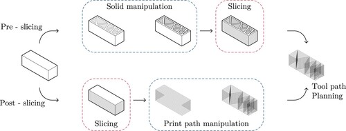
While slicing typically takes place after the material distribution, it is worth noting that the engineering of the material distribution can be either performed before or after this operation. The former case involves the manipulation of the solid geometry to define the material distribution, this will be referred to as pre-slicing optimisation. The latter case involves the direct manipulation of the spatial curves resulting from the slicing process to define the required features of the printing process, which would be a post-slicing optimisation approach. These two alternative workflows are illustrated in . Both processes may yield identical results, however, the approach has a strong influence on the results and the probability of errors. An advantage of pre-slicing is that the toolpath planning step is completely independent, which allows for higher modularity. In smaller-scale 3D printing, solid transformations are often preferable due to the high resolution available. Given the linear deposition used in material extrusion 3D printing, defining the material distribution with volumetric operations and then using a conventional slicer may create uncertainty in the feasibility of the resulting print paths. Moreover, in large-scale processes such as 3DCP, fine control of print paths is critical for quality control. Additionally, post-slicing methods involve direct manipulation of print paths, which removes uncertainty on the further effect of the slicing on the printability of the object.
Figure 2. Alternative workflows for the material distribution and slicing of the geometry for 3D printing.
3.2. Printing orientation
As in other extrusion-based 3D printing processes, 3DCP is based on the layer-by-layer deposition of 2D cross-sections that are stacked together to form a 3D object. In-plane printing provides greater formal freedom, constrained primarily by the continuity of the print paths. By contrast, vertical printing features are limited by support requirements. This requires ensuring proper support for each layer, either by limiting the overhang angles or through the addition of supplementary material dedicated to this purpose. These manufacturing constraints are dependent on the printing orientation, which may be different from the intended use orientation of the part. For example, columns with large overhangs can be printed upside-down to avoid excessive support [Citation9]. However, while the use of support material in 3DCP has been demonstrated [Citation38], it has rarely been applied in practice, probably due to the high cost of the material and the post-processing required to remove the material.
The printing orientation will significantly influence the characteristics and capabilities of the printed element. The first layer will have a flat surface due to the full support from the build platform. Besides impacting support, build orientation determines the direction of the layering, which in turn has an important effect on the subsequent anisotropic properties of the printed part, due to the time differences between the layers [Citation39]. Taking the specific example of a 3DCP beam, the required placement of the main reinforcement along the X-axis at the bottom of the beam will define reinforcement strategies for each printing orientation. Similarly, customised material distributions are more relevant in the longitudinal section, which aligns with the primary plane of flexure of the beam. Each print orientation offers unique benefits and limitations, which are further elaborated in this section and illustrated in . Additionally, a comparative analysis of each printing orientation is summarised in .
Figure 3. Different possible print orientations for a 3DCP beam. The coordinate system refers to the load orientation, that is always applied in the -Z direction.
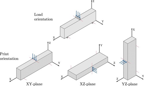
Table 1. Advantages and disadvantages of different 3D printing orientations.
Printing a beam on its base (XY-plane) has the advantage of preserving the planarity of the first layer which allows the correct transfer of loads to the support, without additional processing. Since the part is printed on its target orientation, this is the most common use-case, especially for in-situ printing [Citation31]. Reinforcement most commonly needs to be added manually, for example as straight rebars in the bottom chord of the beam [Citation20]. However, the support requirements limit the possible customisation of material distributions along the longitudinal section of the beam.
A beam printed on its longitudinal section (XZ-plane) takes advantage of the freedom of movement on the main plane of the beam. Support requirements are mostly given as most structures have a constant section on this plane. Despite this freedom of movement, a continuous flow is a requirement for many 3DCP systems [Citation9,Citation40]. Even in systems where the material flow can be controlled on demand, interruptions of the flow need to be minimised to ensure flow consistency and efficient printing times. Therefore, printing on this orientation becomes fundamentally a toolpath planning problem, as can be seen in the work of Yang et al. ((d)) [Citation19]. As it has been studied in other types of material extrusion 3D printing, these process-related limitations can be included as part of the optimisation problem [Citation41]. Following the same principle as in the XY-plane, reinforcement can be placed in-between layers, most commonly as straight rebars in the lower chord of the beam. However, curved reinforcement has been implemented in stress-based optimisation schemas [Citation20,Citation22].
Finally, printing the beam on its cross-section (YZ-plane) requires support along the length of the beam. This allows the customisation of different cross-sections by interpolating them in the longitudinal axis [Citation42]. Whereas this orientation is less advantageous for flexural strength due to the multiple interfaces between layers, this is most commonly supplemented by using vertical reinforcement, which is supplied as a separate process [Citation43]. Examples of this orientation typically use post-tensioned reinforcement to supply the required tensile strength [Citation16,Citation44,Citation45]. Another restriction is the height of the print. When printing on its smaller section, the height is only achieved by the subsequent stacking of layers, which requires substantial strength development to avoid collapse. A common strategy is to print several parts simultaneously to increase the time difference between layers and consequently the development of yield stress during the print. Vertical build rates are limited by the properties of the fresh material and are mostly feasible for bi-component mixes where an accelerator is added at the nozzle [Citation46].
3.3. Variable filament width
Modulating the relationship between the extrusion and travelling speed allows for controlling the width of the filament across the 3DCP process. Either of these two parameters can be calibrated so that the volume of material extruded matches the volume of the filament deposited, this is called ‘nominal speed’. Printing with stiff cementitious materials is most commonly carried out at this nominal speed, as deviating from this balance may lead to problems such as filament tearing or buckling, as highlighted by Wolfs et al. [Citation47]. When printing with soft printable materials, the modulation of the printing speeds allows the gradation of the printing filament [Citation48]. This flexibility in adjusting the filament dimensions not only allows for optimising material use but also provides a powerful tool for extending the design domain of 3DCP.
The relationship between travelling and extrusion speed and the resulting filament has been studied by several researchers. The rheological principles of concrete extrusion have been well-reviewed in multiple studies [Citation10,Citation49]. Comminal et al. provided a detailed insight into the physics of concrete deposition using Computer Fluid Dynamics (CFD) [Citation50]. Similarly, Wolfs et al. studied methods for filament control and their consequences [Citation47]. Furthermore, the modulation of these printing parameters has been used to actively control the filament dimensions. Tay et al. presented a study with several printing parameters and their corresponding resulting filament dimensions and printing qualities [Citation51]. In this work, the authors printed sections at a higher speed to deliberately induce tearing and therefore create weak parts that act as support and can be manually removed after the print. This higher printing speed induces tearing of the filament and is used as support material. In later work, the authors use this method to create a topology-optimised beam by modulating the speed to create areas with full material extrusion and support material, which is presented as a functionally graded material [Citation18]. Yuan et al. presented a method for closed-loop feedback to control the filament width [Citation48]. Unlike the previous examples, the use of soft printing material allows the modulation of the filament width. In their study, a special segmentation script is used to extract the middle line for the printing path and the corresponding extrusion speed to match the expected print width. Conversely, this study uses a pre-slicing approach, that modulates the printing speeds to achieve variable filament widths throughout the print. In order to limit this variation to one side of the print, a compensation algorithm shifts the print paths proportionally to the expected filament width, thus creating a flush surface. By reversing the side to which the control points are shifted, the variations can be constrained to either side, as illustrated in .
Figure 4. Alignment options for variable filament width. By shifting the control points the effect of the variable width can be restricted to either side of the print.
Systems based on industrial robots offer greater acceleration capabilities, making preferable the modulation of the travelling speed [Citation40]. It is common also for robotic controls to have a separate speed control for the pump, making it easier to alter the travelling speed while keeping a constant extrusion speed [Citation9,Citation20]. By contrast, large-scale gantry systems often have a large mass that limits the possibilities for adjusting the travelling speeds due to their high inertia. These systems often have synchronised screw extruders that, conversely, make it easier to modulate the extrusion speed. This distinction underlines the importance of considering the specific capabilities and constraints of the chosen 3DCP system when determining the optimal printing parameters.
4. Methods
The proposed method for internal optimisation of concrete elements is implemented in the design and fabrication of topology-optimised beams. The methodology for altering the material distribution is based on a pre-slicing approach i.e. based on the manipulation of print paths. This approach is characterised by several design considerations: Firstly, the printing orientation is restricted to printing the beam on its base (cf. XY-plane in Section 3.2). Secondly, the print paths must constitute a continuous loop on each layer. Lastly, a minimum quantity of material is predefined to maintain the external boundary of the element and to furnish support for subsequent layers.
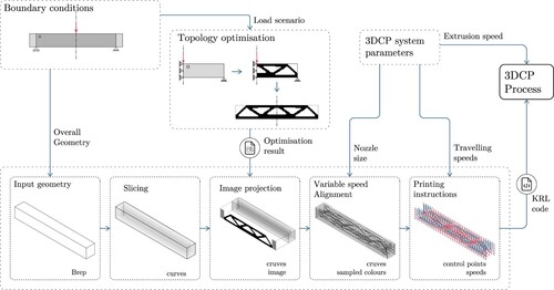
This optimisation problem is typically formulated with an aspect ratio of 6:1, span distance to height respectively [Citation53]. The standard for testing flexural strength in concrete defines the span as three times the height of the specimen [Citation52]. Moreover, given the available resolution when printing with a 20 mm nozzle, the achievable amount of detail would be limited for a shorter beam. Therefore, the optimisation problem was kept consistent, and the test specimens were designed to comply as much with the standard while deviating to accommodate the longer aspect ratio of the optimisation problem, as displayed in . The overall geometry of the beam alongside its boundary conditions, serve as input for a 2D TO problem that yields a representation material distribution as a raster image. The greyscale values of this bitmap are then used to modulate the dimensions of the printed filament by controlling the printing speed for each control point. This procedure is implemented as an integrated design-to-manufacture workflow that incorporates design, optimisation, and manufacturing instructions within a single software environment, as represented in . Manufacturing instructions for robotic fabrication are generated within this integrated workflow.
Figure 5. Left: Diagram showing the overall dimensions of the proposed beam specimens and the design space (Ω) for the topology optimisation problem. Right: Definition of the testing for flexural strength of hardened concrete using a centre-point loading method, in accordance EN 12390-5:2019 [Citation52].
![Figure 5. Left: Diagram showing the overall dimensions of the proposed beam specimens and the design space (Ω) for the topology optimisation problem. Right: Definition of the testing for flexural strength of hardened concrete using a centre-point loading method, in accordance EN 12390-5:2019 [Citation52].](/cms/asset/04b54cdb-08c3-46ef-8f35-f468c1e6a35a/nvpp_a_2346290_f0005_ob.jpg)
Figure 6. Design-to-manufacture workflow for the generation of the optimised beams (OPT-A and OPT-B).
4.1. Topology optimisation problem
The TO in this study is based on the algorithm for minimum compliance based on a modified Solid Isotropic Material with Penalization (SIMP) method. This algorithm's primary aim is to find the material distribution within a given design space that minimises the total compliance, or in other words, maximises the stiffness of the structure under given loads and boundary conditions. The SIMP method interpolates between material and void, using a penalisation factor to discourage intermediate density values. While the SIMP methodology offers a robust framework for optimising material distribution, it inherently presents several limitations in accurately capturing the complex behaviour of unreinforced concrete. This is largely due to the method's foundational assumptions of isotropic material properties and linear elasticity, which fall short of encompassing the inherently anisotropic nature of concrete. Particularly, the differing responses to tensile and compressive forces introduces non-linearities that are critical to structural performance but are not directly addressed by the SIMP framework. The SIMP method is based on the seminal 99-line MATLAB code published by Ole Sigmund in 2001 [Citation54]. The TO method used in this study is based on posterior Python implementations of this method [Citation55].
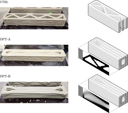
The problem definition exploits the inherent symmetry of the problem by modelling only half of the structure (cf. ), thus reducing computational complexity while preserving the problem's integrity. The FEM problem is modelled as a 2D problem with a design domain that is discretised into a grid, resulting in a total of 1200 elements with a mesh size of 5 mm. The topology-optimised beams are divided into two different optimisation parameters. The volume fraction is defined as 0.5 for both beams, where the first beam (OPT-A) uses a fully converged solution where the solid-void (S-V) fraction tends to 1. Contrarily, the second beam (OPT-B) uses a non-converged state of the same optimisation problem that is stopped at an S-V fraction of 0.25, which yields a result that features smooth gradients instead of contrasting solid and void regions.
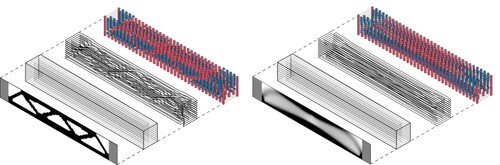
Optimised beams were designed by projecting an optimisation target into the print paths obtained from slicing the overall geometry of the part. Additional manufacturing constraints are considered when generating fabrication instructions for the robotic system. These print paths are then modified to follow this material distribution using 3DCP with variable filament width ().
Figure 7. Diagram showing the projected optimisation result to the print paths from the slicing process. These print paths are then modified according to the projected image producing a variable-speed printing process. Left: OPT-A. Right: OPT-B.
4.2. Design of the prototypes
In order to grade the amount of material in different parts of the printed element, the width of the printed filament is modulated according to the specified density from the TO results. The variable filament width is achieved by modulating the travelling speed of the printing nozzle, which is inversely proportional to the cross-section of the extruded filament. The proposed design is based on a double-wall print path that forms a single continuous path, which is then modified with a variable width according to the TO results, as illustrated in . For filled parts in the optimisation, the width of the filament is adjusted to 25 mm i.e. covering the full width of the printed beam with four lines, as it can be observed in . The proposed printing strategy relies on the possibility of merging the thicker sections to provide stability during the print. While the results from the TO indicate zones with no material, the translation to manufacturing enforces a minimum of material that serves to preserve the functional boundary of the element as well as support material for the upcoming layers. Void sections were dimensioned at 16 mm i.e. reducing the material to 64% when compared to the solid parts of the print. This material is important to comply with the boundary of the printed element and to serve as support for upper layers. In order to keep the external faces flat, the print paths were shifted inwards according to the filament width, as explained in Section 3.3.
Figure 8. Print path design with modulated filament thickness according to TO results. Left: The section of the TO is projected to the double-wall print path. Right: The values sampled from the image determine the printing speed and modify the print path to align the external surface of the printed element.
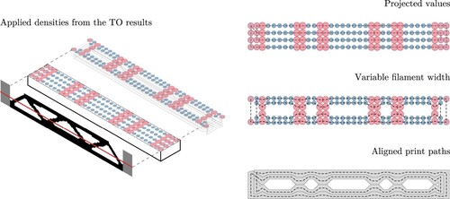
Figure 9. Print paths with printing speed for all the samples. Left: CTRL (constant). Centre: OPT-A (variable). Right: OPT-B (variable).
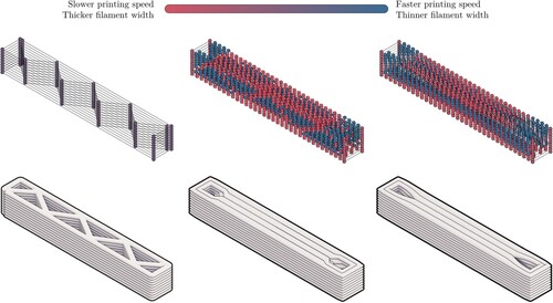
In terms of printing speed, the short sides of the beam are printed at a constant rate, while the long sides are printed at variable speeds following the TO results. These results were sampled at intervals of 20 mm, the same dimensions as the printing nozzle. The resulting internal structure reflects the optimisation pattern while the external surfaces comply with the boundary of the volume of the element, as depicted in .
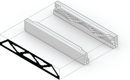
Figure 10. The resulting internal structure reflects the optimisation pattern delineated by the TO, whilst the external surfaces remain congruent with the predefined volumetric boundary of the element.
Previous studies have used cast and solid 3D printed beams for comparison, for which the advantages of 3DCP over cast concrete have already been reported [Citation18,Citation22]. Furthermore, solid beams are seldom used in real-case scenarios. Therefore, this study uses a 3D printed beam with a zigzag infill structure as a control (designated CTRL). This beam represents the typical printing pattern used for 3DCP [Citation56], which has been used from the early days of the technology [Citation49]. The lattice infill pattern allows for a higher moment of inertia and therefore print stability while minimising the amount of material and printer movements [Citation57]. All the beams used in this study share the same dimensions, measuring mm
. They were subjected to the same loading scenario, with a centred point load applied over a 600 mm span. presents a summary of the main parameters of the test specimens.
Table 2. Overall characteristics of the beam test bodies.
4.3. Equipment and setup
The beams were printed at the Digital Fabrication Laboratory at the KTH School of Architecture. The robotic system utilised for the 3DCP process is based on a KUKA KR-16 robot coupled with a specially developed screw-based concrete extruder (). The transparent container allows to have visual feedback from the movement of the material inside the extruder. The build surface is made of film plywood, with dimensions mm. To control the extrusion rate, speeds need to be set up manually, but the extruder controlling system includes a start/stop function that can be sent directly from the robot code. While the extruder system can precisely start/stop the flow, extensive start and stop is avoided as it affects the consistency of the material extrusion. The printing process relies on an open-loop system following a preprogrammed path and with a constant extrusion speed. For each beam type, three identical specimens were manufactured. The resulting printed beams are displayed in .
Figure 11. 3DCP robotic fabrication setup at the KTH School of Architecture.
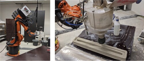
Figure 12. Pictures of the 3D printed concrete beams and illustrations of their respective cross-section at the mid-point.
All beams were printed using Sikacrete-751 3D [Citation58], a mono-component dry-mix that has been specifically formulated for 3DCP applications and is commercially available. This material is mixed with water according to the manufacturer's specifications and fed into the extruder in small batches to ensure a continuous flow. To ensure the material remains in a fluid state, it is mixed continuously during the printing process. The extrusion process starts with freshly mixed concrete being fed into the extruder until it reaches optimal rheological behaviour, which is assessed visually. Once a uniform material flow is achieved, the extrusion speed is adjusted to the standard printing speed (24 RPM) and then moved to print a calibration segment before the print. The extrusion speed is calibrated at the beginning of each printing session to ensure the appropriate filament dimensions, but then kept constant for the rest of the printing operation. Subsequent modulation of the printing speed are controlled by varying the travelling speed of the extruder, which is specified in the instructions executed by the robotic controller. Each beam was printed using a batch of material, and a new batch was prepared at the end of the previous one in a continuous process. After printing the beams were covered with plastic and left to set for 24 hours. Following this period, they were stored in a climate-controlled curing chamber at 20C and 99% relative humidity.
4.4. Testing and validation
Tests took place after 13 days at the Department of Civil and Architectural Engineering at KTH. The printed samples were tested in three-point bending, based on the SS-EN 12390–5 Standard for flexural strength [Citation52]. Loading by a centre-point load was preferred due to the correspondence to the TO problem. To ensure good contact between the beam and the load-applying steel plate, low-density fibre boards were placed between the beam and the load plate. The bottom surface is flat due to the contact with the printing base and therefore was placed directly on top of the support rollers. The tests were controlled by the position of the loading piston, at a rate of 0.55 mm/minute.
5. Results
All samples presented failure in the middle section, under the load point, as it can be observed in . This failure pattern is consistent with what is typically observed in unreinforced concrete structures, where a single vertical crack often appears directly under the load point, which is the area of maximum stress and therefore the most likely location for the concrete to fail. The results show a significant increase in maximum load for the optimised designs, especially when compared in terms of maximum load per weight. Both optimised beam designs performed better than the reference CTRL beam, resulting in a 47% and 63% higher maximum load-to-weight ratio for OPT-A and OPT-B, respectively. Results from the testing are summarised in and plotted in .
Figure 13. Testing of the 3DCP samples.
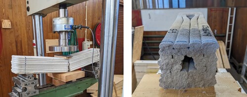
Figure 14. Chart with the results of the tests.
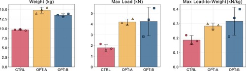
Table 3. Results of the test specimens.
Usually, flexural strength is calculated based on the cross-section of the beam, according to the Standard [Citation36]. However, using rectangular cross-sections for the calculation would not provide meaningful results in this case, given the irregular cross-section of the 3D printed geometry. Additionally, using the bulk mm
will only replicate the ratios given by the maximum load, since all the samples share the same overall dimensions.
6. Discussion
The integrated design-to-manufacture workflow presented in this study offers a significant advantage over conventional fragmented workflows by integrating manufacturing aspects as part of the design phase, enabling a more dynamic and adaptable design process. However, one of the challenges of this method is its customisation aspect; each application may require unique adaptations, making it difficult to establish a one-size-fits-all solution. An advantage of this workflow resides in its modularity, as advanced TO methods can be seamlessly integrated in the same workflow. Therefore, while the integration of this workflow opens up new routes for innovation in design and manufacturing, its scalability and generalisability across different projects remain areas for further investigation.
The use of a compensation parameter allows the effect of the variation in the filament's thickness to be restricted to the inside of the print. While the applied pattern is still subtly discernible from the exterior, the external faces of the printed part maintained the overall boundary of the element, which serves as support for applying arbitrary material distributions and facilitates its integration as architectural elements in 3DCP construction.
As is commonly the case with 3D printed concrete samples [Citation29], the spread in results is higher than for cast concrete. Although the printing parameters were constant, there was some variation in the flow. This inconsistency is evident in the spread of the weights of the printed beams and is most likely attributable to the manual feeding of the material into the extruder. Further improvements in the feeding procedure and a larger number of samples may alleviate this issue.
While both OPT-A and OPT-B presented higher maximum load mean values, OPT-B performed better than OPT-A. Whereas OPT-A represented a fully converged result, the rationale behind the unconverged optimisation was made specifically to avoid large contrasting disparities in the internal structure, favouring instead smooth gradients. These smooth gradients in OPT-B also provide better support for upper layers, as it can be observed in the cross sections of , and therefore yields a more cohesive internal structure than the contrasting values in OPT-A. Nevertheless, the first sample of OPT-B performed significantly worse than the other two samples, and it may be a product of a singular defect and less representative of the performance of the design. The scope of this study was intentionally focused on the design for fabrication aspect, limiting the influence of different TO parameters, which represent a potential pathway for further improving the results of this study.
While the maximum loads were directly obtained from the testing, the calculation of flexural strength is less applicable given the irregular cross-section of the test bodies. Moreover, even if calculating the theoretical or empirical second moment of inertia for the middle cross-section of the beams, analytical solutions assume a constant cross-section along the segmenting the beam into smaller sections where the cross section may be assumed to be constant. Although these calculations may be theoretically feasible, the observed range of variation among different samples render these calculations less relevant.
7. Concluding remarks
3DCP allows an extended range of possibilities for concrete construction that allows extended geometric complexity with almost no additional effort. Yet, despite the enhanced possibilities offered by 3DCP to produce intricate structures, this freedom of shape is still bounded by process constraints. This paper presented a novel method for applying TO patterns to 3D printed concrete components while preserving their external geometry. It leverages the capability of extruding concrete in a flowing state to vary the filament width by modulating the printing speed to embed structurally informed shapes in a continuous printing process. The results show a significant increase in the load-bearing capabilities in terms of maximum load. While the samples tested in this study were restricted to a single unreinforced beam, the method is not constrained to these specific boundary conditions. This approach is mostly relevant for slender elements such as beams or walls, where 2D optimisation patterns can be applied along the shortest dimension of the element. Given that these structural members constitute a substantial portion of the applications of 3DCP within the construction industry, this strategy holds the potential for optimising the material use and structural performance of 3DCP. The potential to optimise the material use and structural performance of these components opens a promising route for future research and development for improving efficiency and reducing the environmental impact of the industry. Consequently, it represents a promising path for reducing the environmental impact of the construction sector. Future research will focus on the application of this method to other structural elements and investigate additional functionalities conferred by the preservation of the external boundary of the element, such as acoustic and thermal properties.
Acknowledgments
The printing sessions were carried out with the fabrication assistance of Adam Varga the Digital Fabrication Laboratory at the School of Architecture at KTH Royal Institute of Technology. Mechanical tests were completed at the Department of Civil and Architectural Engineering, also at KTH, with the support of Viktor Brolund.
Disclosure statement
No potential conflict of interest was reported by the author(s).
Data availability
The data that support the findings of this study are available from the corresponding author, upon reasonable request.
Additional information
Funding
References
- Craveiro F, Duarte JP, Bartolo H, et al. Additive manufacturing as an enabling technology for digital construction: a perspective on construction 4.0. Autom Constr. 2019 Jul;103:251–267 doi: 10.1016/j.autcon.2019.03.011.
- Flatt RJ, Roussel N, Cheeseman CR. Concrete: an eco material that needs to be improved. J Eur Ceram Soc. 2012 Aug;32(11):2787–2798 doi: 10.1016/j.jeurceramsoc.2011.11.012.
- Silfwerbrand J. Concrete and sustainability – some thoughts from a Swedish horizon. Nord Concr Res. 2020 Dec;63(2):79–87 doi: 10.2478/ncr-2020-0019.
- Wangler T, Roussel N, Bos FP, et al. Digital concrete: a review. Cem Concr Res. 2019 Sept;123:105780. doi: 10.1016/j.cemconres.2019.105780.
- Menna C, Mata-Falcón J, Bos FP, et al. Opportunities and challenges for structural engineering of digitally fabricated concrete. Cem Concr Res. 2020 Jul;133:106079. doi: 10.1016/j.cemconres.2020.106079.
- Wangler T, Lloret E, Reiter L, et al. Digital concrete: opportunities and challenges. RILEM Tech Lett. 2016 Oct;1:67–75 doi: 10.21809/rilemtechlett.2016.16.
- Buswell RA, Leal de Silva WR, Jones SZ, et al. 3D printing using concrete extrusion: a roadmap for research. Cem Concr Res. 2018 Oct;112:37–49 doi: 10.1016/j.cemconres.2018.05.006.
- Buswell RA, Da Silva WL, Bos FP, et al. A process classification framework for defining and describing digital fabrication with concrete. Cem Concr Res. 2020 Aug;134:106068. doi: 10.1016/j.cemconres.2020.106068.
- Anton A, Reiter L, Wangler T, et al. A 3D concrete printing prefabrication platform for bespoke columns. Autom Constr. 2021 Feb;122:103467. doi: 10.1016/j.autcon.2020.103467.
- Mechtcherine V, Bos FP, Perrot A, et al. Extrusion-based additive manufacturing with cement-based materials – production steps, processes, and their underlying physics: a review. Cem Concr Res. 2020 Jun;132(132):106037. doi: 10.1016/j.cemconres.2020.106037.
- Flatt RJ, Wangler T. On sustainability and digital fabrication with concrete. Cem Concr Res. 2022 May;158:106837. doi: 10.1016/j.cemconres.2022.106837.
- Robayo-Salazar R, Mejía de Gutiérrez R, Villaquirán-Caicedo MA, et al. 3D printing with cementitious materials: challenges and opportunities for the construction sector. Autom Constr. 2023 Feb;146:104693. doi: 10.1016/j.autcon.2022.104693.
- Bi M, Tran P, Xia L, et al. Topology optimization for 3D concrete printing with various manufacturing constraints. Addit Manuf. 2022 Sept;57:102982. doi: 10.1016/j.addma.2022.102982.
- McConaha M, Venugopal V, Anand S. Design tool for topology optimization of self supporting variable density lattice structures for additive manufacturing. J Manuf Sci Eng. 2021 Feb;143(7):071001. doi: 10.1115/1.4049507.
- Wu J, Aage N, Westermann R, et al. Infill optimization for additive manufacturing – approaching bone-like porous structures. IEEE Trans Vis Comput Graph. 2018 Feb;24(2):1127–1140 doi: 10.1109/TVCG.2017.2655523.
- Vantyghem G, De Corte W, Shakour E, et al. 3D printing of a post-tensioned concrete girder designed by topology optimization. Autom Constr. 2020 Apr;112:103084. doi: 10.1016/j.autcon.2020.103084.
- Ooms T, Vantyghem G, Tao Y, et al. The production of a topology-optimized 3D-printed concrete bridge. In: Buswell R, Blanco A, Cavalaro S, et al. editors. Third RILEM international conference on concrete and digital fabrication. Cham: Springer International Publishing; 2022. p. 37–42.
- Tay YWD, Lim JH, Li M, et al. Creating functionally graded concrete materials with varying 3D printing parameters. Virtual Phys Prototyp. 2022 Mar;17(3):662–681 doi: 10.1080/17452759.2022.2048521.
- Yang W, Wang L, Ma G, et al. An integrated method of topological optimization and path design for 3D concrete printing. Eng Struct. 2023 Sept;291:116435. doi: 10.1016/j.engstruct.2023.116435.
- Breseghello L, Naboni R. Toolpath-based design for 3D concrete printing of carbon-efficient architectural structures. Addit Manuf. 2022 Aug;56:102872. doi: 10.1016/j.addma.2022.102872.
- Amir O, Shakour E. Simultaneous shape and topology optimization of prestressed concrete beams. Struct Multidiscipl Optim. 2018 May;57(5):1831–1843 doi: 10.1007/s00158-017-1855-5.
- Breseghello L, Hajikarimian H, Jørgensen HB, et al. 3DLightBeam+. Design, simulation, and testing of carbon-efficient reinforced 3D concrete printed beams. Eng Struct. 2023 Oct;292:116511. doi: 10.1016/j.engstruct.2023.116511.
- Torelli G, Fernández MG, Lees JM. Functionally graded concrete: design objectives, production techniques and analysis methods for layered and continuously graded elements. Constr Build Mater. 2020 May;242:118040. doi: 10.1016/j.conbuildmat.2020.118040.
- Hernández Vargas J, Westerlind H, Silfwerbrand J. Grading material properties in 3D printed concrete structures. Nord Concr Res. 2022 Jul;66(1):73–89 doi: 10.2478/ncr-2022-0004.
- Bos F, Wolfs R, Ahmed Z, et al. Additive manufacturing of concrete in construction: potentials and challenges of 3D concrete printing. Virtual Phys Prototyp. 2016;11(3):209–225 doi: 10.1080/17452759.2016.1209867.
- Duballet R, Gosselin C, Roux P. Additive manufacturing and multi-objective optimization of graded polystyrene aggregate concrete structures. In: Thomsen MR, Tamke M, Gengnagel C, et al. editors. Modelling behaviour: design modelling symposium 2015. Cham: Springer International Publishing; 2015. p. 225–235. [accessed 2021 Mar 5].
- Ahmed Z, Bos F, van Brunschot M, et al. On-demand additive manufacturing of functionally graded concrete. Virtual Phys Prototyp. 2020;15(2):194–210 doi: 10.1080/17452759.2019.1709009.
- Ma G, Buswell R, Leal da Silva WR, et al. Technology readiness: a global snapshot of 3D concrete printing and the frontiers for development. Cem Concr Res. 2022 Jun;156:106774. doi: 10.1016/j.cemconres.2022.106774.
- Mechtcherine V, Fataei S, Bos FP, et al. Digital fabrication with cement-based materials: underlying physics. In: Roussel N, Lowke D, editors. Digital fabrication with cement-based materials: state-of-the-art report of the RILEM TC 276-DFC. Cham: Springer International Publishing; 2022. p. 49–98.
- Bos FP, Menna C, Pradena M, et al. The realities of additively manufactured concrete structures in practice. Cem Concr Res. 2022 Jun;156:106746. doi: 10.1016/j.cemconres.2022.106746.
- Huang S, Xu W, Li Y. The impacts of fabrication systems on 3D concrete printing building forms. Front Archit Res. 2022 Aug;11(4):653–669 doi: 10.1016/j.foar.2022.03.004.
- Li S, Xin Y, Yu Y, et al. Design for additive manufacturing from a force-flow perspective. Mater Des. 2021 Jun;204:109664. doi: 10.1016/j.matdes.2021.109664.
- Gibson I, Rosen D, Stucker B, et al. Additive manufacturing technologies. Cham: Springer International Publishing; 2021. doi: 10.1007/978-3-030-56127-7
- Pontes AJ. Chapter 7 -- Designing for additive manufacturing. In: Pouzada AS editor. Design and manufacturing of plastics products. William Andrew Publishing; 2021 Jan. p. 249–292.
- Zhang X, Liou F. Chapter 1 -- Introduction to additive manufacturing. In: Pou J, Riveiro A, Davim JP, editors. Additive manufacturing. Amsterdam, Netherlands: Elsevier; 2021 Jan. p. 1–31.
- ISO. Standard -- Additiv tillverkning -- Allmänna principer -- Grunder och terminologi (ISO/ASTM 52900:2021) SS-EN ISO/ASTM 52900:2021 (No. ISO/ASTM 52915:2020). 2021. [accessed 2023 Jan 24]. Available from: https://www.sis.se/produkter/terminologi-och-dokumentation/ordlistor/produktionsteknik-ordlistor/ss-en-isoastm-529002021/.
- Associates RM. Rhino and grasshopper developer documentation; n.d. [accessed 2023 Nov 9]. Available from: https://developer.rhino3d.com/.
- Gaudillière N, Duballet R, Bouyssou C, et al. Chapter 3 -- building applications using lost formworks obtained through large-scale additive manufacturing of ultra-high-performance concrete. In Sanjayan JG, Nazari A, Nematollahi B, editors. 3D concrete printing technology. Oxford, UK: Butterworth-Heinemann; 2019 Jan. p. 37–58.
- Wolfs RJM, Bos FP, Salet TAM. Hardened properties of 3D printed concrete: the influence of process parameters on interlayer adhesion. Cem Concr Res. 2019 May;119:132–140 doi: 10.1016/j.cemconres.2019.02.017.
- Breseghello L, Naboni R. Adaptive toolpath: enhanced design and process control for robotic 3DCP. In: Gerber D, Pantazis E, Bogosian B, et al. editors. Computer-aided architectural design. Design imperatives: the future is now. Singapore: Springer; 2022. p. 301–316.
- Xia L, Bi M, Wu J, et al. Integrated lightweight design method via structural optimization and path planning for material extrusion. Addit Manuf. 2023 Jan;62:103387. doi: 10.1016/j.addma.2022.103387.
- Yu R. A digital workflow for the design and manufacturing of 3D printed concrete bridges in a circular economy: structural design considerations for pre-stressed beams and dry connections [EngD Thesis]. EindhovenTechnische Universiteit Eindhoven; 2022.
- Kloft H, Empelmann M, Hack N, et al. Reinforcement strategies for 3D-concrete-printing. Civ Eng Des. 2020;2(4):131–139doi: 10.1002/cend.202000022.
- Gebhard L, Mata-Falcón J, Anton A, et al. Aligned interlayer fibre reinforcement and post-tensioning as a reinforcement strategy for digital fabrication. In: Bos FP, Lucas SS, Wolfs RJ, et al. editors. Second RILEM international conference on concrete and digital fabrication. Cham: Springer International Publishing; 2020. p. 622–631.
- Salet TAM, Ahmed ZY, Bos FP, et al. Design of a 3D printed concrete bridge by testing. Virtual Phys Prototyp. 2018 Jul;13(3):222–236 doi: 10.1080/17452759.2018.1476064.
- Wangler T, Pileggi R, Gürel S, et al. A chemical process engineering look at digital concrete processes: critical step design, inline mixing, and scaleup. Cem Concr Res. 2022 May;155:106782. doi: 10.1016/j.cemconres.2022.106782.
- Wolfs RJM, Salet TAM, Roussel N. Filament geometry control in extrusion-based additive manufacturing of concrete: the good, the bad and the ugly. Cem Concr Res. 2021 Dec;150:106615. doi: 10.1016/j.cemconres.2021.106615.
- Yuan PF, Zhan Q, Wu H, et al. Real-time toolpath planning and extrusion control (RTPEC) method for variable-width 3D concrete printing. J Build Eng. 2022 Apr;46:103716. doi: 10.1016/j.jobe.2021.103716.
- Roussel N. Rheological requirements for printable concretes. Cem Concr Res. 2018 Oct;112:76–85 doi: 10.1016/j.cemconres.2018.04.005.
- Comminal R, Leal da Silva WR, Andersen TJ, et al. Modelling of 3D concrete printing based on computational fluid dynamics. Cem Concr Res. 2020 Dec;138:106256. doi: 10.1016/j.cemconres.2020.106256.
- Tay YWD, Li MY, Tan MJ. Effect of printing parameters in 3D concrete printing: printing region and support structures. J Mater Process Technol. 2019 Sept;271:261–270 doi: 10.1016/j.jmatprotec.2019.04.007.
- ISO. SS-EN 12390-5:2019 Standard -- Provning av hårdnad betong -- Del 5: Böjdraghållfasthet hos provkroppar (No. SS-EN 12390-5). 2019. [accessed 2023 May -25]. Available from: https://www.sis.se/produkter/byggnadsmaterial-och-byggnader/byggnadsmaterial/betong-och-betongprodukter/ss-en-12390-52019/.
- Gaynor AT, Guest JK. Topology optimization considering overhang constraints: eliminating sacrificial support material in additive manufacturing through design. Struct Multidiscipl Optim. 2016 Nov;54(5):1157–1172 doi: 10.1007/s00158-016-1551-x.
- Sigmund O. A 99 line topology optimization code written in Matlab. Struct Multidiscipl Optim. 2001 Apr;21(2):120–127 doi: 10.1007/s001580050176.
- Hunter W. Topy -- topology optimization with python. GitHub; 2017. Available from: https://github.com/williamhunter/topy.
- Zhang J, Khoshnevis B. Optimal machine operation planning for construction by contour crafting. Autom Constr. 2013 Jan;29:50–67 doi: 10.1016/j.autcon.2012.08.006.
- He R, Li M, Gan VJL, et al. BIM-enabled computerized design and digital fabrication of industrialized buildings: a case study. J Clean Prod. 2021 Jan;278:123505. doi: 10.1016/j.jclepro.2020.123505.
- Sikacrete® -751 3D. n.d. [accessed 2023 Oct 12]. Available from: https://deu.sika.com/de/construction/betonherstellung/fertigteile-und-betonwaren/3d-betondruck/sikacrete-751-3d.html.