
 ?Mathematical formulae have been encoded as MathML and are displayed in this HTML version using MathJax in order to improve their display. Uncheck the box to turn MathJax off. This feature requires Javascript. Click on a formula to zoom.
ABSTRACT
In recent years, there has been a growing focus on additive manufacturing of martensitic stainless steel with exceptional performance. This study introduces a new pathway to fabricate martensitic stainless steel through heterogeneous double-wire arc-directed energy deposition (DED). ER316L and ER70-G are used as raw materials, melting together and forming a common molten pool. A steel block with a chemical composition of Fe-11.38Cr-7.52Ni-1.44Mo-1.54Mn-0.497Si (wt.%) is successfully manufactured. The microstructure, mechanical properties and corrosion resistance of the martensitic stainless steel are investigated. The results indicate that the microstructure of the steel consists of martensite and austenite, achieving satisfactory microhardness (381.38 ± 11.94 HV), tensile strength (1172.1 ± 25.7 MPa), ductility (11.3 ± 1.3%), toughness (146.3 ± 8.0 J) and corrosion resistance (0.865 μA/cm2). This work demonstrates great potential of fabricating martensitic stainless steel using heterogeneous double-wire arc DED, providing a new choice to manufacture martensitic stainless steel and potentially other alloys.
1. Introduction
The demand for steels in various industries is increasing with the development of large structures, as high-strength steels are widely used to effectively reduce weight and enhance service performance [Citation1]. However, ordinary steels are susceptible to corrosion and damage in harsh service environments, leading to structural failures. Martensitic stainless steel, characterised by low carbon content and appropriate alloying elements content, exhibits outstanding mechanical properties and corrosion resistance [Citation2], making it suitable for harsher environments. Additionally, martensitic stainless steel is widely used in marine engineering, automotive, aerospace and other fields due to these advantages [Citation3].
In martensitic stainless steels, the alloying elements, such as C, Cr, Ni and Mo have a profound impact on the solidification structure and properties of the alloy. The C content significantly influences the microstructure and properties of martensitic stainless steel. C acts as an austenite-forming element that stabilises austenite. Its dissolution in the matrix can enhance the strength of martensitic stainless steel. However, excessive C levels can reduce ductility and promote carbide formation, affecting both mechanical properties and corrosion resistance [Citation4,Citation5]. Cr can enhance the hardenability of steels so that the martensitic structure can be obtained at room temperature even under air cooling [Citation6]. Cr is the main forming element of passivation film on stainless steel surface, increasing the pitting potential and corrosion resistance of martensitic stainless steel [Citation7]. However, high Cr content can lead to δ phase precipitation, impacting the plasticity and toughness of martensitic stainless steel [Citation8]. Ni, as an austenite-forming element, can expand the γ phase region, improving the ductility and toughness [Citation9,Citation10]. Ni can shift the self-corrosion potential positively, enhancing corrosion resistance [Citation11]. Besides, Ni can reduce δ ferrite content. However, the Ni content should not be too high; otherwise, the steel may lose its hardenability due to the dual effect of expanding the γ phase region and reducing martensite start (Ms) temperature. Moreover, when used in conjunction with Cr, Mo can significantly improve the hardenability of the steel, suppress or reduce temper brittleness and enhance the performance of stainless steel [Citation12]. Additionally, Mo can enhance the stability of Cr in the passive film, thereby improving the corrosion resistance of stainless steel [Citation13]. However, excessive addition of Mo in the steel can also lead to carbide formation.
The increasing utilisation of martensitic stainless steel in large-scale projects necessitates stringent requirements for production cost and efficiency, particularly in terms of rapid manufacturing and repair of critical structures. Additive manufacturing (AM) may be a better option for such demands [Citation14].
AM, as a rapidly advancing and highly automated technology for printing and forming various materials, has developed rapidly in recent years [Citation15]. Scholars showed significant interests in manufacturing martensitic stainless steel through AM [Citation16] and investigating the microstructure, mechanical properties and corrosion resistance [Citation3,Citation4,Citation17]. Furthermore, some scholars focused on exploring methods to enhance the properties of martensitic stainless steel, such as adding ceramic particles [Citation14], conducting heat treatment [Citation18] or employing special methods [Citation19] and parameters [Citation20]. However, current research in this field typically relies on martensitic stainless steel powders or wires as raw materials, which may be expensive or not readily available in the market. Moreover, conducting additional treatments to improve properties will complicate the process, increase manufacturing costs and reduce efficiency, thereby limiting its application in rapidly producing large components or quickly repairing critical structures during emergencies. It may be an inspiring thing if martensitic stainless steel with superior properties is obtained through a more efficient and less costly pathway.
AM using multi wires has shown a significant improvement in depositing efficiency and cost reduction. It demonstrates proficiency in preparing new materials, particularly when employing heterogeneous multi wires. Many scholars have highlighted the potential of manufacturing alloys using multi heterogeneous wires, such as Ti-22Al-24Nb alloy [Citation21], high-strength Ti alloy [Citation22], Ti-Al alloys [Citation23], Ni-Ti alloys [Citation24], Al-Zn-Mg-Cu alloy [Citation25] and Al-Co-Cr-Fe-Ni high-entropy alloy [Citation26]. However, there is a lack of previous study on fabricating martensitic stainless steel through in-situ alloying. Many studies have shown that martensitic structures will form at the fusion zone of dissimilar steels welded joints of low carbon steel or low alloy steel and stainless steel [Citation27,Citation28], or at the interface of additively manufactured bimetallic structures of stainless steel and low alloy steel [Citation29]. The phenomenon of martensitic structure formation resulting from the mixing of two basic materials provides a new approach for the in-situ fabrication of martensitic stainless steel using austenitic stainless steel and low alloy steel metal wires, without the need for martensitic stainless steel.
An approach to obtain martensitic stainless steel with wonderful performance via double-wire arc additive manufacturing (DWA-AM) is proposed in this study. Specifically, two heterogeneous wires of ER316L and ER70-G are fed together at a designed wire feed speed ratio and melt simultaneously. This study successfully fabricated a martensitic stainless steel in situ, with a composition of Fe-11.38Cr-7.52Ni-1.44Mo-1.54Mn-0.497Si (wt.%). Furthermore, it exhibited excellent performance. Besides, the approach proposed in this study is efficient, convenient and low-cost, which may have great application prospects in preparing or repairing the components with strict requirements for mechanical properties and corrosion resistance in nuclear power, shipbuilding, weaponry and other fields or in surface modification of mild steel to enable it cope with harsh environment.
2. Experiments
2.1. Materials and method
In this study, a stainless steel (SS) wire ER316L and a low alloy steel (LAS) wire ER70-G, both with diameters of 1.2 mm, were used as raw materials. Additionally, a low carbon steel Q235 with a thickness of 10 mm was used as substrate. The chemical composition of the materials is listed in . It is apparent that ER316L exhibits higher levels of alloying elements, while ER70-G contains lower levels of these elements.
Table 1. Chemical composition of materials used and theoretical chemical composition of the new steel in this work (wt.%).
In addition, the two wires will melt together to form a common molten pool, and the chemical composition of the molten pool is determined by the melting amounts of the two wires. Furthermore, the weight percentage of a certain chemical element can be calculated according to the following formula [Citation21]:
(1)
(1) where w, ρ, S and f represent weight percentage, density, cross-sectional area of deposit layer and wire melting rate, respectively while sign ‘1’ and ‘2’ represent ER316L and ER70-G respectively. Due to the same diameter of the two wires, S1 is equal to S2. And the density of the two metal wires is similar, so ρ1 is approximately equal to ρ2. So formula 1 can be written as the following formula:
(2)
(2) where w1 and w2 are certain quantity, so the chemical composition of the molten pool is determined by the melting rate of ER316L and ER70-G, that is the wire feed speed in a steady state. In this study, the wire feed speed ratio of ER316L to ER70-G is set at 3:2 as an illustrative example, and the chemical composition of the alloy obtained is similar to martensitic stainless steel. The theoretical chemical composition of the new steel is listed in , and it is named as Fe11Cr8Ni for convenience.
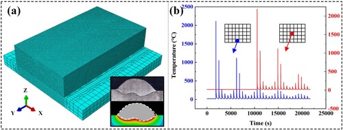
(a) shows the schematic diagram of the additive manufacturing system. ER316L and ER70-G are fed through two GMA torches, each controlled by a separate welding power source. This setup allows for independent adjustment of the parameters for the two wires. In addition, 80% Ar + 20% CO2 was employed as shielding gas for each torch, and the gas flow rate was both 20 L/min. During the experiment, the two torches were fixed on a six-axis robot to realise the movement of the torches. And the two torches were arranged side by side during the experiment, with vertical angles denoted as α and β respectively, forming an inverted triangle shape. The distance of the ends of the two wires was d, and the ends of the wires were 1 mm from the substrate, as shown in (b).
Figure 1. Schematic diagram of (a) additive manufacturing system, (b) torches arrangement and (c) deposition strategy. (d) Micro CT results. (e) Tests samples cutting strategy.
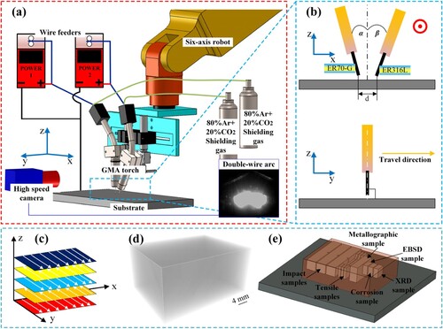
Before the additive manufacturing process, the substrate was cleaned with an angle grinder to eliminate rust and wiped with acetone. The experiment involved the use of a double-wire synchronous deposit scheme, where the two wires burned synchronously to form a common molten pool, and a new alloy emerged after solidification. Prior to the additive manufacturing of martensitic stainless steel, the influence of double wires spacing on composition and formation of the deposit layer was investigated by adjusting the distance between the ends of the two wires.
Following the characterisation of the additive manufacturing process, the additive manufacturing of martensitic stainless steel block was initiated, and the detail parameters of the deposition process are listed in . In this work, multi-layer and multi-pass deposition scheme was adopted, and the total number of deposit layers of the block was 5 and there were 7 parallel passes in each layer, as shown in (c). Following the fabrication of the steel block, micro-CT analysis was conducted to examine the existence of defects. (d) shows the result, exhibiting no defects. Subsequently, the test samples were cut from the additively manufactured martensitic stainless steel block using wire electrical discharge, as shown in (e). All test samples are kept away from the substrate to avoid composition dilution zone. The tensile samples and impact samples are prepared according to GB/T 228.1-2010 and GB/T 229-2022. The metallographic sample, electron backscattered diffraction (EBSD) sample, corrosion sample and X-ray Diffraction (XRD) sample were initially ground with sandpapers ranging from 180# to 1500#, followed by polishing with 2.5 μm diamond polishing paste until achieving a bright mirror-like surface finish. Subsequently, the samples were rinsed with alcohol and dried using a dryer.
Table 2. Parameters of the deposition process.
2.2. Microstructure characterisation
XRD was used for measuring the phase composition at a scanning speed of 0.03 °/s. The surface of metallographic sample was wiped with a cotton ball containing FeCl3 and HCl aqueous solution for 12 s. After completing the etching process, the sample was rinsed and dried. The cross-section of the martensitic stainless steel block was observed by an optical microscope (OM) and scanning electron microscopy (SEM), which allowed for the acquisition of metallographic photographs of the manufactured steel. In addition, the micro-area composition of the sample was quantitatively analysed by an energy dispersive spectrometer (EDS). For more crystallographic information, EBSD was conducted after removing the damaged layer of the EBSD sample (with a surface area of 1.5 cm2) by electro-polishing using a solution containing perchloric acid and alcohol for 40 s. The results were analysed through TSL OIM Analysis software.
2.3. Mechanical and corrosion properties testing
Microhardness tests were conducted on the metallographic sample using a Vickers hardness tester, with a 1 mm interval between two test points. A testing load of 200 gf was applied for 15 s. Tensile tests were performed through a computer-controlled electronic universal testing machine, with a tensile rate of 2 mm/min at room temperature. Charpy impact tests were performed through an impact tester at room temperature. Following the tensile tests and impact tests, the fracture morphology of the test samples was observed by SEM, and EDS was used to determine the chemical composition of the particles at the fracture site.
Electrochemical tests were conducted using a three-electrode workstation to analyse the corrosion behaviour of the steel obtained via this method, Moreover, the working electrodes were the samples obtained in this work with a surface area of 1.5 cm2, moreover, a saturated calomel electrode served as the reference electrode, and a platinum electrode served as the auxiliary electrode. These electrodes were immersed in a 3.5 wt.% NaCl solution, and potentiodynamic polarisation tests were performed at a scanning rate of 0.5 mV/s at room temperature.
3. Results and discussion
3.1. Processing feasibility
In the additive manufacturing process, the original solid metal undergoes a complex melting and solidification process. The chemical composition and cooling rate of the molten pool play a crucial role in determining the solidification mode and microstructure. For stainless steel, the difference between the Cr equivalent (Creq) and Ni equivalent (Nieq) results in four distinct solidification modes during the solidification process [Citation30].
(3)
(3)
(4)
(4)
(5)
(5)
(6)
(6) where L represents liquid, γ represents austenite and δ represents ferrite.
The Creq and Nieq can be calculated according to the following two formulas [Citation31]:
(7)
(7)
(8)
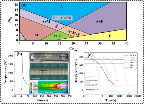
(8) By calculating, the Creq and Nieq are approximately 13.724% and 10.417%, respectively. The Creq/Nieq value is 1.32, suggesting that the theoretical solidification mode may be AF mode [Citation32]. In the solidification process, γ phase is initially formed, followed by the formation of δ phase. Subsequently, as the cooling continues, the δ phase would transform into γ phase. Besides, the solidification behaviour is also affected by the cooling rate. The δ phase may be absent at room temperature, which is attributed to the higher cooling rate and lower Creq/Nieq value [Citation33]. Moreover, the microstructure can be predicted roughly using Schaeffer phase diagram [Citation2], as shown in (a), suggesting a mixture of martensite (M) and austenite (A) at room temperature for Fe11Cr8Ni. Additionally, (b) shows the thermal cycling curve of the deposit layer by numerical simulation using ABAQUS. (c) shows the Continuous Cooling Transformation (CCT) curve of Fe11Cr8Ni, calculated by using JMatPro and the blue line represents the cooling rate of Fe11Cr8Ni, also indicating that the microstructure of Fe11Cr8Ni may be a mixture of martensite and austenite at room temperature.
Figure 2. (a) Schaeffer phase diagram. (b) Thermal cycling curve of the deposit layer. (c) CCT curve of Fe11Cr8Ni.
3.2. Processing characteristics
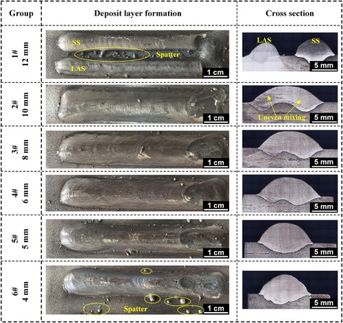
The effect of double wires spacing on the formation as well as the composition uniformity of deposit layers was investigated by varying double wires spacing from 12 mm to 4 mm, while keeping other process parameters constant. shows the formation and cross-sectional morphology of the deposit layer obtained when the double wires spacing is 12, 10, 8, 6, 5 and 4 mm. It is evident that when the double wires spacing is 12 mm, ER70-G and ER316L melt to form two distinct molten pools, resulting in the forming of two deposit layers after solidification. When the double wires spacing decreases to 10 mm, the two wires melt to form a common molten pool, and the composition of the two wires begins to mix. However, the cross-sectional morphology reveals that the composition is not evenly mixed, and there are large differences between the left side and right side. At a double wires spacing of 8 mm, there is no visible unevenness after mixing, and it is the same when the double wires spacing was 6, 5 and 4 mm. Notably, when the double wires spacing is greater than 5 mm, two remelted areas are visible on the substrate, caused by the melting of the two wires. But when the double wires spacing reduces to 5 and 4 mm, only one remelted area is observed, which can be explained by the concentration of thermal energy in the centre of the common molten pool when the wires are spaced closely. Synchronous depositing with the two wires plane perpendicular to the travel direction results in small surface curvature of the deposit layer, which is conducive to obtaining smooth and flat components without lacking of fusion when multi-layer and multi-pass additive manufacturing is performed.
Figure 3. Deposit layer formation and cross section obtained by varying the double wires spacing from 12 mm to 4 mm.
The ratio of layer width to layer height (Ratio), the size of deposit layer (Size), the contact angle on left side (Angle-L) and right side (Angle-R) are measured for the six groups experiments to explore the effect of double wires spacing on deposit layer formation and composition more intuitively, as shown in (a). The distance between the two wires in transverse direction can potentially lead to uneven composition of the deposit layer, which is undesirable. Given the substantial differences in the content of Cr and Ni between ER316L and ER70-G, comparing the Cr and Ni content on the leftmost side and rightmost side may serve as a scientific method to evaluate the composition homogeneity of the deposit layer. And the measuring method is shown in (b). To ensure the accuracy of the tests, ten spots are randomly selected as test spots on the leftmost and rightmost position of the cross sections respectively, and the average values are calculated as the content of Cr and Ni on the leftmost and rightmost side (Cr-L, Cr-R, Ni-L, Ni-R).
Figure 4. (a), (b) Schematic diagram of measuring method. (c) Information of the cross-section. (d) Cr and Ni content on the leftmost and rightmost side.
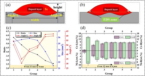
(c) shows the cross-sectional information of the deposit layer. It is evident that with the decrease of the double wires spacing, ratio gradually decreases. Size is observed to be between 35 and 36 mm2 when the double wires spacing is 6 mm or greater. However, size decreases to less than 34 mm2 at a spacing of 5 mm, and it is even less than 32 mm2 at a spacing of 4 mm. The decrease in size may be attributed to the increased interference when the spacing is equal to or less than 5 mm, leading to more spatters and decrease in actual deposit metal. For the contact angle, it is large on both sides when the common molten pool does not form, instead, it decreases to a lower level when the common molten pool forms. Furthermore, both the Angle-L and Angle-R increase with the decrease of double wires spacing after the formation of the common molten pool, which may be related to the lower layer width, higher layer height caused by the smaller double wires spacing.
(d) shows the EDS test results, indicating that with the decrease of the double wires spacing, the variance of the content of Cr and Ni between the left side and right side becomes smaller. And there is almost no difference in the composition when the spacing is equal to or less than 6 mm, which can be considered that the deposit layer composition is uniform. What’s more, the actual values of the content of Cr and Ni are much less than theoretical values, which might result from the dilution of molten pool and substrate.
It is necessary to try to obtain the deposit layer with a large Ratio and a small contact angle, which is conductive to preventing defects and poor formation during multi-layer and multi-pass additive manufacturing. Simultaneously, maintaining homogeneous composition throughout the steel block is essential to prevent performance degradation. Overall, a spacing of 6 mm appears to be a suitable parameter for achieving these objectives.
It has been established that a double wires spacing of 6 mm is suitable for this work. Consequently, the Fe11Cr8Ni block is manufactured by multi-layer and multi-pass additive manufacturing using the parameters listed in . In order to deeply understand the characteristics of the DWA-AM process and obtain the thermal cycle curve, ABAQUS is used to simulate the temperature field during the DWA-AM process. (a) shows the finite element model, which was divided into blending mesh, Besides, the illustration in (a) is the heat source verification result. In (b), the thermal cycle curves of the centre of the fourth pass of the first and the third layers are displayed. Each bead experiences a limited number of high-temperature thermal cycles, which are resulted from the adjacent passes. The peak temperature value of the thermal cycle between two widely spaced beads is smaller.
Figure 5. (a) Meshing of finite element model. (b) Thermal cycle curves of the centre of the fourth pass of the first and third layers.
3.3. Phase composition and microstructure
(a) shows the cross-section of the Fe11Cr8Ni block, exhibiting sound formation without visible defects. EDS was used to analyse the composition along the Z direction, with the results shown in (b). Due to the high arc energy during the additive manufacturing process, the composition of the bottom layer was diluted by the substrate. The actual composition is much lower than the theoretical value. As the distance from the substrate increases, the content of Cr and Ni increases. When the distance from the substrate is greater than 5 mm, the dilution effect becomes less pronounced. Optical Emission Spectrometer was used to measure the actual chemical composition of the Fe11Cr8Ni block, and the results are summarised in , showing close alignment with the theoretical values. Besides, (c) is the XRD pattern of the test sample, showing that α and γ constitute the phase composition of the Fe11Cr8Ni.
Figure 6. (a) Cross-section of Fe11Cr8Ni block. (b) Elements distribution from bottom to top. (c) XRD pattern of the Fe11Cr8Ni.
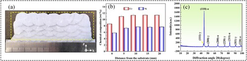
Table 3. Actual chemical composition of Fe11Cr8Ni (wt. %).
(a,d) show the typical metallographic photographs of Fe11Cr8Ni on the XZ surface observed by OM and SEM, presenting the martensite and retained austenite. The austenite is blocky in shape while the martensite appears as lath-like structures, and the retained austenite is distributed among the martensite lath bundles with various orientations. Furthermore, surface relief of martensite caused by the shear from undercooled austenite to martensite is visible. There is high content of alloying elements in Fe11Cr8Ni, like Cr and Ni, which dissolve into austenite and enhance the stability of undercooled austenite, resulting in the enhancement of hardenability and easy access to become martensite.
Figure 7. Typical metallographic photographs of the three alloys observed by (a-c) OM and (d–f) SEM.
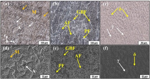
For LAS, proeutectoid ferrite forms first at high temperature during the cooling process, and it is characterised by grain boundary ferrite (GBF) and polygonal ferrite (PF). Moreover, the presence of few alloying elements makes the austenite unstable and it will transform into martensite only reaching the critical quenching rate, or acicular ferrite (AF) will nucleate and form. So the microstructure of LAS is a mixture of GBF, PF and AF at room temperature due to a slower cooling rate, as shown in (b,e). For SS, ferrite (δ) forms from high-temperature liquid, followed by the formation of austenite (γ) from δ-ferrite. Moreover, the presence of more alloying elements results in very high stability of austenite, and it will transform into martensite only when cooling to the Ms temperature which is below room temperature. So the microstructure of SS is a mixture of δ and γ at room temperature, as shown in (c,f).
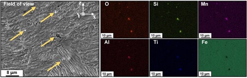
Additionally, there are some particles among the matrix with diameters of 1-2 μm. EDS test results indicate that the particles are rich in O, Si, Mn, Al and Ti elements and contain almost no Fe element, as shown in , suggesting that the particles may be oxides. Because there is CO2 in the shielding gas and O element may dissolve into liquid and form oxide particles with the oxyphile elements such as Si, Mn, Al and Ti. The melting point of oxide particles is relatively high and they will retain from high-temperature liquid to room temperature. What’s more, the oxide may have an effect on the performance of the manufactured steel block.
Figure 8. EDS mapping of O, Si, Mn, Al, Ti and Fe elements of Fe11Cr8Ni at higher magnification.
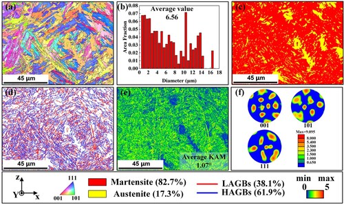
The microstructure of Fe11Cr8Ni is obtained and analysed in the previous text, However, for more crystallographic information, EBSD was employed. illustrates the EBSD results of Fe11Cr8Ni on the XZ surface. (a) is the inverse pole figure (IPF) map of Fe11Cr8Ni, revealing a considerable presence of martensite laths exhibiting diverse growth directions. The observation aligns seamlessly with the outcomes derived from the metallographic photograph obtained by SEM. (b) is the grain size chart and the average diameter of Fe11Cr8Ni within the test area is 6.56 μm, which is a desirable result. (c) is the phase map of Fe11Cr8Ni, illustrating a microstructure comprised predominantly of martensite (red area) and austenite (yellow area). What’s more, the martensite phase accounts for 82.7% while austenite phase accounts for 17.3%. The distribution of austenite amidst the martensite laths appears random, consistent with the preceding analysis. In addition, (d) shows the grain boundary distribution of Fe11Cr8Ni, showcasing a predominant density (61.9%) of high-angle grain boundaries (HAGBs, >15°) while a lower density (38.1%) of low-angle grain boundaries (LAGBs, 2°–15°). The distribution pattern correlates closely with the phase transformation from austenite to martensite. The kernel average misorientation (KAM) map serves as a pivotal tool to determine the degree of grain deformation. As shown in (e), the KAM value is higher in martensite region (green area) while it is at a low level in austenite (blue area) region, which underscores pronounced deformation during the formation of martensite. And the average KAM value is 1.07°. Furthermore, the high KAM signifies an abundance of geometrically necessary dislocations (GNDs), which will impact the properties of the materials. (f) is the pole figure (PF) of martensite phase, suggesting the highest pole density of martensite grain is 9.095.
Figure 9. EBSD results of Fe11Cr8Ni: (a) IPF map, (b) grain size chart, (c) phase map, (d) grain boundary distribution, (e) KAM map and (f) PF of martensite phase.
3.4. Mechanical and corrosion properties
Microhardness tests were conducted on the Fe11Cr8Ni alloy along the Z and X directions, and the distributions are shown in (a,b). Meanwhile, the microhardness results of LAS and SS are also shown in (b). In the Z direction, the microhardness of the bottom layer is greater than that of other regions. It may be related to the dilution of the alloying elements with the substrate. Beyond this region, a homogeneous microhardness distribution is shown along the Z direction. Within the test distance in the X direction, the microhardness values of the three samples exhibit minor fluctuations, potentially attributed to variations in microstructure in different regions. But in general, the microhardness distribution of the samples remains relatively uniform. Additionally, the microhardness value of the Fe11Cr8Ni exceeds that of the LAS and SS, as the typical diamond-shaped indentations shown in (b). Particularly striking is the observation that, under the load of 200 gf for 15 s, Fe11Cr8Ni displays the smallest indentation size. The average microhardness values of Fe11Cr8Ni, LAS and SS are 381.38 ± 11.94 HV, 218.89 ± 11.44 HV and 201.54 ± 7.91 HV, respectively, as shown in (c).
Figure 10. Microhardness distributions along the (a) Z direction and (b) X direction. (c) Microhardness comparison between the three alloys.
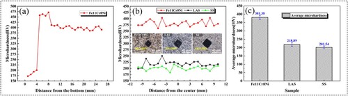
As previously noted, there is a large number of martensite in Fe11Cr8Ni, which is actually a supersaturated solid solution of carbon in α-Fe. And the supersaturated carbon can result in lattice distortion, making the improvement of microhardness. What’s more, the existence of dispersive oxide particles will also result in the improvement of microhardness.
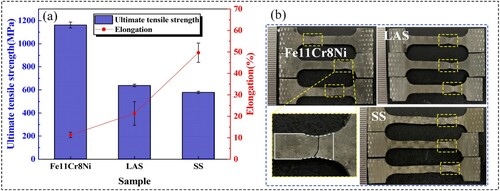
Tensile tests conducted at room temperature indicate that the ultimate tensile strength of Fe11Cr8Ni is 1172.1 ± 25.7 MPa, which is much higher than that of the LAS and SS (638.7 ± 11.2 MPa and 578.3 ± 9.3 MPa, respectively). While the elongation of Fe11Cr8Ni, LAS and SS are 11.3 ± 1.3%, 21.3 ± 5.5% and 49.7 ± 4.5%, respectively. The results are shown in (a). Besides, (b) shows the appearance of the fractured tensile samples. Impact tests conducted at room temperature show that the impact energy of Fe11Cr8Ni sample is 146.3 ± 8.0 J, indicating that Fe11Cr8Ni possesses a strong resistance to impact loads.
Figure 11. (a) Tensile properties comparison between the three alloys. (b) Appearance of the fractured tensile samples.
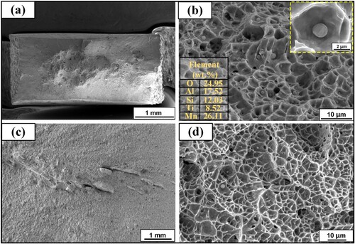
In order to delve deeper into the tensile and impact properties of Fe11Cr8Ni, the fracture morphology of the test samples is observed by SEM. (a,b) show the fracture morphology of fractured tensile sample. Necking can be seen from the macroscopic image of fracture morphology. A noteworthy observation is the abundance of dimples on the fracture surface of Fe11Cr8Ni, indicating a ductile fracture mode of Fe11Cr8Ni, which is an exciting result. Furthermore, there are some second-phase particles in the root of dimples of Fe11Cr8Ni, and EDS tests are performed to figure out the composition of these particles. The results are shown in (b). The high content of O, Al, Si, Ti and Mn, suggests an oxide composition, aligning with the findings from EDS mapping results shown in . During the tensile process, some microvoids may develop and aggregate from these particles, leading to material fracture and failure. (c,d) show the fracture morphology of fractured impact sample. It is satisfactory that the impact sample also fails with a ductile fracture mode.
Figure 12. Fracture surfaces of (a), (b) tensile sample and (c), (d) impact sample of the Fe11Cr8Ni.
The deformation of metal materials is mainly accomplished by dislocation slipping, so any factors that increase the slipping resistance of dislocation can improve materials’ strength. The microstructure of Fe11Cr8Ni is a mixture of martensite and retained austenite. When undercooled austenite transforms into martensite, high density of dislocations form, as the KAM results shown in (e). In addition, the dissolution of supersaturated carbon into martensite leads to lattice distortion. And the dispersive second-phase particles also play a role in hindering the movement of dislocations. Moreover, austenite is a flexible phase, which may contribute to the improved ductility and toughness of Fe11Cr8Ni [Citation34]. Consequently, Fe11Cr8Ni exhibits exceptional tensile strength, ductility and toughness.
The presence of alloying elements, such as Cr, is known to contribute to the exceptional corrosion resistance of metal materials. The composition analysis presented in indicates that Fe11Cr8Ni contains a substantial amount of these elements, suggesting that the corrosion resistance of Fe11Cr8Ni is not weak. Potentiondynamic polarisation tests are conducted in 3.5 wt.% NaCl solution at room temperature. The resulting potentiondynamic polarisation curve of Fe11Cr8Ni is compared with those of LAS and SS, both obtained under identical conditions, as shown in (a). It is clear that Fe11Cr8Ni sample displays a significant passivation zone before pitting like SS sample, in which the current density remains almost unchanged with the increase of polarisation potential, meaning outstanding corrosion resistance of Fe11Cr8Ni.
Figure 13. (a) Potentiondynamic polarisation curve of the three alloys. (b) Ecorr and Icorr of the three alloys. (c1), (c2) Schematic diagram of corrosion behaviour.
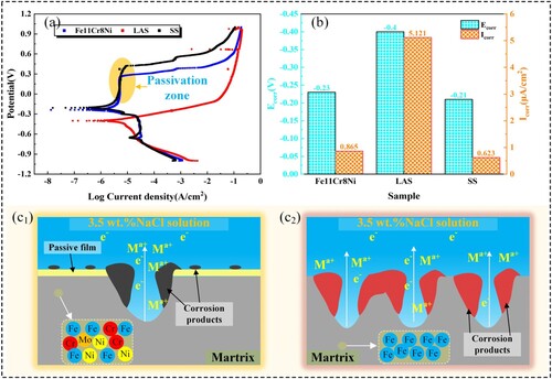
The corrosion potential (Ecorr) and corrosion current density (Icorr) are two significant parameters to characterise corrosion resistance, which provides insights into corrosion tendency and corrosion rate. (b) shows the Ecorr and Icorr of the three alloys by fitting. The Ecorr of Fe11Cr8Ni, LAS and SS are −0.23 V, −0.4 V and −0.21 V. The Icorr of Fe11Cr8Ni, LAS and SS are 0.865, 5.121 and 0.623 μA/cm2, respectively, suggesting that the corrosion resistance of Fe11Cr8Ni is quite promising, only slightly worse than SS, which can broaden the application fields of Fe11Cr8Ni where corrosion resistance is strictly required.
Relevant research has demonstrated that Cr plays a pivotal role in enhancing the corrosion resistance of steels. The higher the Cr content, the more outstanding the corrosion resistance becomes. The phenomenon is attributed to the formation of Cr2O3 on the surface of the samples, acting as a passive film that effectively prevents corrosion [Citation35], as shown in (c1). In addition, a layer of corrosion products containing Cr(OH)3 will form and attach to the surface of the materials which offers further defence against corrosion [Citation36]. On the contrary, if the Cr content is too low to have passivating effect, the corrosion resistance of the material is going to be great poor, as shown in (c2).
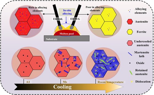
In this study, a martensitic stainless steel block is successfully manufactured via DWA-AM by employing stainless steel wire ER316L and low alloy steel wire ER70-G. And it can be characterised as an in-situ process, as shown in . The two dissimilar metal wires melt and form a common molten pool, where high heat input facilitates the diffusion of elements. Then, the new alloy molten pool undergoes a phase transition from liquid to solid, with austenite forming during the cooling process. As the temperature drops below A1, austenite becomes unstable, exhibiting a tendency to transform into martensite. The Gibbs free energy of both undercooled austenite and martensite rise as temperature dropping, and the Gibbs free energy rise rate of undercooled austenite exceeds that of martensite. The difference in Gibbs free energy between the two phases, along with undercooling, act as the driving force for phase transformation. When the driving force is equal to resistance, martensite starts to form, and the transformation continues as temperature dropping until to room temperature. The martensitic stainless steel fabricated in this work possesses appropriate alloying elements, leading to the appearance of martensite and austenite at room temperature. This achievement highlights the controlled and tailored manufacturing of a martensitic stainless steel with desirable properties through DWA-AM process.
Figure 14. Martensitic stainless steel forming process in this work.
The experimental and analytical results demonstrate the successful manufacturing of martensitic stainless steel with wonderful properties through DWA-AM. The study goes further to compare the ultimate tensile strength and elongation of Fe11Cr8Ni with several martensitic stainless steels that were built without any additional means to improve properties, as shown in . It is clear that it is a challenging task to obtain the martensitic stainless steel with wonderful strength and ductility directly. The fact that the manufactured martensitic stainless steel possesses simultaneously wonderful strength and ductility, coupled with the high efficiency and low cost of the manufacturing process using common market-available metal wires, is indeed inspiring news. In this study, the example alloy of Fe11Cr8Ni was fabricated and studied. The independent control of the two metal wires during the fabrication process offers significant potential for preparing Fe-based alloys with a wide range of compositions. This capability will be a focal point of our future research endeavours. By utilising this method, we can explore and develop new Fe-based alloys with tailored properties and characteristics to cope with different service environments.
Figure 15. Comparison of ultimate tensile strength and elongation between this work and other works of martensitic stainless steel as built without other treatment [Citation3,Citation37–48].
![Figure 15. Comparison of ultimate tensile strength and elongation between this work and other works of martensitic stainless steel as built without other treatment [Citation3,Citation37–48].](/cms/asset/f7674879-70d9-49ad-8b35-fc9c73d016a6/nvpp_a_2350610_f0015_oc.jpg)
4. Conclusions
In this study, a martensitic stainless steel block is in situ fabricated using ER316L and ER70-G two dissimilar metal wires via double-wire arc additive manufacturing. The process characteristics as well as the microstructure, mechanical properties and corrosion resistance are investigated in detail. The conclusions are as follows:
The preparation of an alloy closely matching commercially available martensitic stainless steel using ER316L and ER70-G as raw materials is feasible. A martensitic stainless steel block with a homogeneous composition was successfully manufactured.
The microstructure of Fe11Cr8Ni consists of a mixture of martensite (82.7%) and austenite (17.3%), with some oxide particles among the matrix.
The Fe11Cr8Ni alloy exhibits exceptional mechanical properties, including high microhardness (381.38 ± 11.94 HV), impressive strength (1172.1 ± 25.7 MPa), favourable ductility (11.3 ± 1.3%) and toughness (146.3 ± 8.0 J).
Electrochemical tests at room temperature demonstrate wonderful corrosion resistance of the martensitic stainless steel, exhibiting lower corrosion rate (0.865 μA/cm2).
Disclosure statement
No potential conflict of interest was reported by the author(s).
Data availability statement
The raw/processed data required to reproduce these findings cannot be shared at this time as the data also forms part of an ongoing study.
Additional information
Funding
References
- Wang X, Li W, Yao Y, et al. In-situ alloyed ultrahigh strength steels via additive manufacturing. Addit Manuf. 2023;77:103825. doi:10.1016/j.addma.2023.103825
- Li F, Liu Y, Kong H, et al. Insight on microstructure and mechanical properties of 40 mm thick-walled ferromagnetic super-MSS by magnetic-field-assisted narrow gap GTAW. J Mater Res Technol. 2023;24:5805–5822. doi:10.1016/j.jmrt.2023.04.117
- Wu L, Khan DF, Zhang C, et al. Microstructure and mechanical characterization of additively manufactured Fe11Cr8Ni5Co3Mo martensitic stainless steel. Mater Charact. 2023;203:113106. doi:10.1016/j.matchar.2023.113106
- Gao B, Xu T, Wang L, et al. Achieving a superior combination of tensile properties and corrosion resistance in AISI420 martensitic stainless steel by low-temperature tempering. Corros Sci. 2023;225:111551. doi:10.1016/j.corsci.2023.111551
- Neri MA, Colás R. Analysis of a martensitic stainless steel that failed due to the presence of coarse carbides. Mater Charact. 2001;47(3):283–289. doi:10.1016/S1044-5803(01)00189-9
- Villa M, Grumsen FB, Niessen F, et al. Aging 17-4 PH martensitic stainless steel prior to hardening: effects on martensitic transformation, microstructure and properties. Materialia. 2023;32:101882. doi:10.1016/j.mtla.2023.101882
- Yuan F, Wei G, Gao S, et al. Tuning the pitting performance of a Cr-13 type martensitic stainless steel by tempering time. Corros Sci. 2022;203:110346. doi:10.1016/j.corsci.2022.110346
- Rosenauer A, Brandl D, Ressel G, et al. Influence of delta ferrite on the impact toughness of a PH 13-8 Mo maraging steel. Mater Sci Eng A. 2022;856:144024. doi:10.1016/j.msea.2022.144024
- Ravi Kumar B, Sharma S, Munda P, et al. Structure and microstructure evolution of a ternary Fe–Cr–Ni alloy akin to super martensitic stainless steel. Mater Design. 2013;50:392–398. doi:10.1016/j.matdes.2013.03.035
- Hao K, Gong M, Pi Y, et al. Effect of Ni content on rolling toughness of laser-arc hybrid welded martensitic stainless steel. J Mater Process Tech. 2018;251:127–137. doi:10.1016/j.jmatprotec.2017.08.029
- Yang X, Jia J, Li X, et al. Enhanced hydrogen induced stress corrosion cracking resistance of Ni-advanced weathering steel by Ni and Mn modification. Constr Build Mater. 2023;408:133820. doi:10.1016/j.conbuildmat.2023.133820
- Tian J, Chen K, Li H, et al. Suppressing grain boundary embrittlement via Mo-driven interphase precipitation mechanism in martensitic stainless steel. Mater Sci Eng A. 2022;833:142529. doi:10.1016/j.msea.2021.142529
- Tang Y, Li B, Shi H, et al. Simultaneous improvement of corrosion and wear resistance of Fe–Mn–Al–C lightweight steels: the role of Cr/Mo. Mater Charact. 2023;205:113274. doi:10.1016/j.matchar.2023.113274
- Chen W, Xu L, Zhang Y, et al. Additive manufacturing of high-performance 15-5PH stainless steel matrix composites. Virtual Phys Prototyp. 2022;17(2):366–381. doi:10.1080/17452759.2021.2019793
- Nagaraj MH, Maiaru M. A novel higher-order finite element framework for the process modeling of material extrusion additive manufacturing. Addit Manuf. 2023;76:103759. doi:10.1016/j.addma.2023.103759
- Martina F, Ding J, Williams S, et al. Tandem metal inert gas process for high productivity wire arc additive manufacturing in stainless steel. Addit Manuf. 2019;25:545–550. doi:10.1016/j.addma.2018.11.022
- Seede R, Shoukr D, Zhang B, et al. An ultra-high strength martensitic steel fabricated using selective laser melting additive manufacturing: densification, microstructure, and mechanical properties. Acta Mater. 2020;186:199–214. doi:10.1016/j.actamat.2019.12.037
- Habib SA, Mates SP, Zhang F, et al. Effect of austenite fraction and stability on strength-hardening-ductility in additively manufactured 17-4 PH stainless steel containing nitrogen. Mater Sci Eng A. 2023;878:145180. doi:10.1016/j.msea.2023.145180
- Cho Y, Park S, Kim J, et al. 17-4ph stainless steel with excellent strength–elongation combination developed via material extrusion additive manufacturing. J Mater Res Technol. 2023;24:3284–3299. doi:10.1016/j.jmrt.2023.03.228
- Lyu Z, Sato YS, Xu W, et al. Simultaneous enhancements of strength and ductility of wire arc additive manufactured 17-4PH steel via intrinsic heat treatment. J Mater Process Tech. 2023;321:118149. doi:10.1016/j.jmatprotec.2023.118149
- Li Z, Cui Y, Yu Z, et al. In-situ fabrication of Ti2AlNb-based alloy through double-wire arc additive manufacturing. J Alloy Compd. 2021;876:160021. doi:10.1016/j.jallcom.2021.160021
- Han J, Zhang G, Chen X, et al. High strength Ti alloy fabricated by directed energy deposition with in-situ Cu alloying. J Mater Process Tech. 2022;310:117759. doi:10.1016/j.jmatprotec.2022.117759
- Xiong J, Liu G, Yu Y. Fabricating TiAl alloys with various compositions by twin-wire arc AM. Mater. Manuf. Process. 2024;39(3):310–319. doi:10.1080/10426914.2023.2195905
- Han J, Chen X, Zhang G, et al. Microstructure and mechanical properties of Ni50.8Ti49.2 and Ni53Ti47 alloys prepared in situ by wire-arc additive manufacturing. J Mater Process Tech. 2022;306:117631. doi:10.1016/j.jmatprotec.2022.117631
- Wang L, Wu T, Wang D, et al. A novel heterogeneous multi-wire indirect arc directed energy deposition for in-situ synthesis Al-Zn-Mg-Cu alloy: process, microstructure and mechanical properties. Addit Manuf. 2023;72:103639. doi:10.1016/j.addma.2023.103639
- Shen Q, Kong X, Chen X. Fabrication of bulk Al-Co-Cr-Fe-Ni high-entropy alloy using combined cable wire arc additive manufacturing (CCW-AAM): microstructure and mechanical properties. J. Mater Sci Technol. 2021;74:136–142. doi:10.1016/j.jmst.2020.10.037
- Zhou W, Yue J, Zhong P, et al. Investigation on weld forming, microstructure and mechanical characteristics of dissimilar steel GTAW under novel composite magnetic field. Int J Pres Ves Pip. 2024;209:105177. doi:10.1016/j.ijpvp.2024.105177
- Chen H, Ng FL, Du Z. Hybrid laser-tig welding of dissimilar ferrous steels: 10 mm thick low carbon steel to 304 austenitic stainless steel. J Manuf Process. 2019;47:324–336. doi:10.1016/j.jmapro.2019.10.013
- Chen Y, Zuo X, Zhang W, et al. Enhanced strength-ductility synergy of bimetallic laminated steel structure of 304 stainless steel and low-carbon steel fabricated by wire and arc additive manufacturing. Mater Sci Eng A. 2022;856:143984. doi:10.1016/j.msea.2022.143984
- Li K, Li D, Liu D, et al. Microstructure evolution and mechanical properties of multiple-layer laser cladding coating of 308 l stainless steel. Appl Surf Sci. 2015;340:143–150. doi:10.1016/j.apsusc.2015.02.171
- Mokhtabad Amrei M, Verreman Y, Bridier F, et al. Microstructure characterization of single and multipass 13Cr4Ni steel welded joints. Metall Microstruct Anal. 2015;4(3):207–218. doi:10.1007/s13632-015-0202-8
- Li W, Liu X, Yamamoto M, et al. Research on interface characteristics of 308 l stainless steel coatings manufactured by laser hot wire cladding. Surf Coat Technol. 2021;427:127822. doi:10.1016/j.surfcoat.2021.127822
- Benoit MJ, Tabaie S, Waqar T, et al. Effects of additive manufacturing processes and isothermal aging on the microstructure and properties of 13-8 mo precipitation hardening martensitic stainless steel. Addit Manuf. 2023;72:103615. doi:10.1016/j.addma.2023.103615
- Wang XL, Huang AR, Shang CJ, et al. Characterization of the cladding layer by laser cladding of 9Cr18Mo powder on 3Cr14 martensitic stainless steel and the impact of martensite obtained through post heat treatment on hardness. Mater Today Commun. 2022;32:104057. doi:10.1016/j.mtcomm.2022.104057
- Feng H, Dai J, Li H, et al. Sn microalloying enhances corrosion resistance of stainless steel by accelerating heterogeneous nucleation of passive film. Corros Sci. 2022;201:110279. doi:10.1016/j.corsci.2022.110279
- Liu H, Zhang W, Zhao Z, et al. Broken passive film and subsequent pitting corrosion behavior of 2205 duplex stainless steel induced by marine fungus aspergillus terreus in artificial seawater. Corros Sci. 2023;218:111147. doi:10.1016/j.corsci.2023.111147
- Chen W, Xiao B, Xu L, et al. Additive manufacturing of martensitic stainless steel matrix composites with simultaneously enhanced strength-ductility and corrosion resistance. Compos Part B: Eng. 2022;234:109745. doi:10.1016/j.compositesb.2022.109745
- Fabian R, Hadadzadeh A. Breaking strength-ductility trade-off in laser-powder bed fused Fe–Cr–Ni–Al maraging stainless steel: controlled precipitation and preserved dislocations. Mater Sci Eng A. 2023;868:144761. doi:10.1016/j.msea.2023.144761
- Ghaffari M, Vahedi Nemani A, Nasiri A. Microstructure and mechanical behavior of PH 13–8Mo martensitic stainless steel fabricated by wire arc additive manufacturing. Addit Manuf. 2022;49:102374. doi:10.1016/j.addma.2021.102374
- Ghaffari M, Vahedi Nemani A, Shakerin S, et al. Grain refinement and strengthening of PH 13-8Mo martensitic stainless steel through TiC/TiB2 inoculation during wire arc additive manufacturing. Materialia. 2023;28:101721. doi:10.1016/j.mtla.2023.101721
- Liu D, Su J, Wang A, et al. Tailoring the microstructure and mechanical properties of FeCrNiCoMo maraging stainless steel after laser melting deposition. Mater Sci Eng A. 2022;840:142931. doi:10.1016/j.msea.2022.142931
- Riabov D, Frisk K, Thuvander M, et al. Design and characterization of a cobalt-free stainless maraging steel for laser-based powder bed fusion. Mater Design. 2022;223:111180. doi:10.1016/j.matdes.2022.111180
- Samei J, Asgari H, Pelligra C, et al. A hybrid additively manufactured martensitic-maraging stainless steel with superior strength and corrosion resistance for plastic injection molding dies. Addit Manuf. 2021;45:102068. doi:10.1016/j.addma.2021.102068
- Song J, Tang Q, Feng Q, et al. Effect of remelting processes on the microstructure and mechanical behaviours of 18Ni-300 maraging steel manufactured by selective laser melting. Mater Charact. 2022;184:111648. doi:10.1016/j.matchar.2021.111648
- Tian WP, Jin ZQ, Wang XR, et al. Wire-arc directed energy deposition super martensitic stainless steel with excellent strength and plasticity. J Manuf Process. 2023;103:11–22. doi:10.1016/j.jmapro.2023.08.006
- Zhu B, Lin J, Lei Y, et al. Additively manufactured δ-ferrite-free 410 stainless steel with desirable performance. Mater Lett. 2021;293:129579. doi:10.1016/j.matlet.2021.129579
- Zou X, Niu B, Pan L, et al. Wire + arc additive manufacturing and heat treatment of super martensitic stainless steel with a refined microstructure and excellent mechanical properties. Materials (Basel). 2022;15(7):2624. doi:10.3390/ma15072624
- Vahedi Nemani A, Ghaffari M, Salahi S, et al. Effects of post-printing heat treatment on the microstructure and mechanical properties of a wire arc additive manufactured 420 martensitic stainless steel part. Mater Sci Eng A. 2021;813:141167. doi:10.1016/j.msea.2021.141167