
 ?Mathematical formulae have been encoded as MathML and are displayed in this HTML version using MathJax in order to improve their display. Uncheck the box to turn MathJax off. This feature requires Javascript. Click on a formula to zoom.
ABSTRACT
Multi-material additive manufacturing holds immense potential for performance and functionality enhancement. Past research efforts primarily focused on the horizontal interface (perpendicular to the sample build direction) during the laser-powder bed fusion (LPBF) of multi-materials, whereas a few studies demonstrated that the vertical interface (parallel to the sample build direction) is in fact the main obstacle towards high-integrity multi-material fabrication in a three-dimensional space. In this work, facilitated by our own patented powder spreading device, we explored the mechanisms behind defect formation along both the horizontal and vertical interfaces during the LPBF production of 316L stainless steel and K220 copper multi-materials. High-fidelity fluid dynamics simulations were also conducted to rationalise the experimental observations. A practical process parameter optimisation approach is also proposed at the end, with the aim of mitigating those large defects currently occurring near the vertical interface.
Metal additive manufacturing (AM) (i.e. laser-powder bed fusion (LPBF), electron beam powder bed fusion (EBPBF) and direct energy deposition (DED)) has evolved from a rapid prototyping tool to an important material processing technique towards practical applications [Citation1,Citation2]. Productions of industrially relevant materials via AM is a common sight now [Citation3–7]. Expanding the functionalities of AM-built components through multi-material (aka functionally graded materials, FGMs) manufacturing holds the key to unlock new frontiers of product design and performance improvement [Citation8–12], which could potentially benefit numerous sectors such as fusion, biomedical, aerospace, etc. [Citation13]. Yet, the fabrication of high-integrity bi-metallic interface (not only perpendicular to the sample build direction, but also in the orthogonal orientation) is still an ongoing challenge, preventing industrial adoptions of AM-built multi-materials [Citation14].
Among the various materials used for AM-built FGMs, steel-copper bi-metal parts have aroused growing interest in both research and industry communities. With the potential benefits to couple the excellent electrical/thermal conductivity of copper and the good mechanical strength of steel, copper-steel bi-metal could serve in various fields such as power generation, die casting, heat transfer components and electric conductors.’ However, it is a non-trivial task to derive defect-free bi-metallic interfaces [Citation15]. The rationale for such a material combination stems from the high mechanical loading ability of steel and the superior thermal conductivity of copper [Citation16]. It is recognised that when producing copper alloy with martensitic steels, e.g. 300 maraging steel and T2 copper [Citation17], 07Cr15Ni5 martensitic steel and CuCr alloy [Citation18], it is often not an issue to achieve defect-free interfaces. However, the same cannot be said for stainless steels, which actually have a wider industrial application due to their excellent corrosion resistance. The underlying mechanism for such a difference in crack propensity between martensitic and stainless steels can be ascribed to their distinct modes of solidification. In general, most martensitic steels solidify as the high-temperature body-centred cubic (BCC) phase, which has a higher crack resistance than stainless steels which solidify as the face-centred cubic (FCC) phase, due to its lower segregation tendencies for most detrimental elements (e.g. sulphur and phosphorus) [Citation19].
Indeed, the presence of cracking along horizontal bi-metallic interfaces was observed when producing stainless steel and copper multi-materials via AM, e.g. 316L stainless steel (316L SS) with C18400 [Citation20] and 316L SS with CuSn10 [Citation21]. Several crack-mitigation methods were subsequently proposed. To obtain crack-free interfaces, Zhang et al. introduced a nickel interlayer between the steel and copper alloys during the directed energy deposition (DED) process [Citation22,Citation23]. Nickel alloy (IN718) was found to have a similar effect on a following steel-copper study [Citation24]. Research efforts on the effect of processing parameters towards material mixing near the interface were also carried out, with the assistance of either machine learning [Citation25] or experimental compositional gradients [Citation26]. Both methods concluded that processing parameter optimisations should be tailored for material mixers near the interfacial regions.
On top of the frequently reported issue of cracks along the horizontal interfaces as mentioned previously, the defects near vertical interfaces (i.e. interfaces parallel to the build direction) seem to pose an even greater challenge. Schneck et al. employed laser-powder bed fusion (LBPF) to produce a case study on multi-material injection nozzle with tool steel 1.2709 and copper alloy CW106C [Citation27]. Severe defects were detected near the vertical bi-metallic interface, which resulted in part delamination and the failure of the entire component. Meyer et al. explored different configurations of linking 316L SS and CuCrZr alloy, and they also found that vertical interfaces contained much larger and a higher number density of defects [Citation28]. Despite its greater impact on the quality of multi-material fabrication in a three-dimensional space, limited research is available for the vertical interface.
In this work, we aim to understand the mechanisms behind the defect formation during the LPBF production of exemplary 316L SS and K220 copper alloys via experimental and modelling methods. Tailor-made multi-material specimens encompassing both horizontal and vertical interfaces are fabricated via a patented LPBF device [Citation29]. A practical processing optimisation approach on the production of high-integrity vertical interfaces will also be proposed.
The multi-material fabrication was conducted within a LPBF machine SLM 250 HL (SLM Solutions, Germany). A customised multi-compartment hopper was designed to spread different types of powders during the LPBF process. The hopper takes advantage of the unique powder spreading mechanism with the SLM 250 HL machine, in which two separate rollers can control the type of powder to be deposited, when the powders are placed into different compartments. Details of the design can be retrieved from the granted US patent [Citation29]. 316L SS and K220 Cu particles with sizes ranging from 20 to 63 μm were used to build the sample. The processing parameters adopted for the 316L SS were laser power of 175 W, scanning speed of 550 mm/s, layer thickness of 50 μm and a hatch spacing of 90 μm. For the K220 Cu, while keeping the layer thickness and hatch spacing constant, the laser power was 625 W, and the laser scanning speed was 530 mm/s. These parameters are borrowed from the previous inhouse research efforts. The steel substrate was heated to 100°C during the sample production to minimise residual stresses. The oxygen content was kept below 200 ppm throughout the fabrication to prevent oxidation.
The equilibrium phase diagram between 316L SS and K220 Cu was computed using Thermo-Calc 2024a, with the TCFE12 database. The composition of 316L SS was taken as Fe-10.6Ni-18.9Cr-2.1Mn-1.9Si-1.2Mo (wt.%), and the composition of K220 Cu was Cu-3.1Ni-1.3Si-0.4Cr (wt.%). The as-built specimens were removed from the substrate via the electrical discharge machining (EDM). Specimens were mounted within PolyFast carbon resin prior to grinding using SiC-paper, down to #4000 grit. 3 and 1 μm diamond suspensions were used for sample polishing, and a final step of vibratory polishing was carried out with the colloidal silica suspension. Optical microscopy (OM) was conducted within Olympus BX53M microscope equipped with Olympus stream motion 2.3.3 software. Scanning electron microscopy (SEM) and energy dispersive X-ray spectroscopy (EDX) were carried out using JEOL JSM 7600F with an Oxford Xmax Detector (Xmax 50). EDX line scan data was smoothed with the ‘loess function’ within the OriginPro software for clearer interpretation.
A multi-material computational fluid dynamics (CFD) model was established to understand the thermo-fluid evolutions during LPBF of 316L SS and K220 Cu. Details of the mathematical descriptions can be found in a previous study [Citation30]. Various calculations were conducted on a domain of dimension 1440 μm × 400 μm × 600 μm, which is discretised into uniform cartesian grid with a size of 5 μm. The thermophysical properties of the simulations are listed in supplementary Table S1. Initial configurations of the powder bed and the substrate are displayed in supplementary Figure S1. The temperature field, flow velocity and compositional distribution were extracted from the results to analyse the melt pool dynamics during LPBF of 316L SS and K220 Cu.
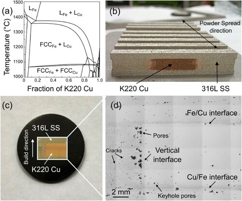
The equilibrium phase diagram between 316L SS and K220 Cu is displayed in (a). As Fe and Cu are mutually immiscible, they exist as individual liquid phases at high temperatures ( and
) [Citation31]. Upon cooling, FCC Fe phase first solidifies around 1350°C and coexists with liquid Cu, (
and
). Finally, after the FCC Cu phase appears at about 1070°C, a full solid of
and
forms. In the current LPBF experiment, the K220 Cu is deposited in the centre of the as-built 316L SS material, (b). The horizontal interfaces between the K220 Cu and 316L SS are sharp, but the vertical interfaces are less confined. This diffuse vertical interface is more obvious after polishing, (c). Within the enlarged OM view, three distinct interfaces can be detected, namely the 316L SS over K220 Cu (Fe/Cu) interface, K220 Cu over 316L SS (Cu/Fe) interface, and the 316L SS and K220 Cu side-by-side (vertical) interface, (d). Compared to the two horizontal interfaces, more defects, i.e. large pores (∼500 μm in diameter) and cracks (∼150 μm in length), are detected beside the vertical interface, mostly existing within the 316L SS region. Smaller cracks are also found to occur near the horizontal interfaces, but only visible under a higher magnification. The characteristics and mechanisms for the crack occurrence at different interfaces will be illustrated and discussed separately.
Figure 1. (a) Equilibrium phase diagram between 316L SS and K220 Cu. (b) As-built multi-material specimens with K220 Cu in the centre and the SS316 in the periphery. (c) Polished sample with its build direction pointing upwards. (d) Optical image of the cross-section, highlighting three different interfaces, Fe over Cu (Fe/Cu), Cu over Fe (Cu/Fe), and the vertical interface.
When depositing 316L SS over K220 Cu, the interface is not uniform, and there is a transition zone between the pure K220 Cu (yellow) and the pure 316L SS (blue) (a). For the bottom of this transition zone, elongated ‘solutal bands’ composed of Fe are detected and marked with black arrows, (b). The morphology of these bands suggests that the liquid flow trajectories within the individual melt pools during laser-material interactions. At the interface between these Fe-enriched solutal bands and the Cu matrix, a thin strip (∼500 nm) of white Cu matrix free of black Fe particles is detected, highlighted by the enlarged view within the red box. It is hypothesised that those as-solidified Fe particles within this region diffused into the larger Fe-enriched solutal bands during the cooling stage, to minimise the system’s overall Gibbs free energy. At the top of the transition zone, cracks are observed with an average length of ∼50 μm (a and c). Also, Cu is found to be present along some non-cracked grain boundaries of the solidified 316L SS, evident by its white contrast under the backscattered electron (BSE) imaging condition. A representative enlarged view is illustrated within the red rectangular box in (c). It is yet unclear if the copper infiltration took place before or after any crack occurrence.
Figure 2. 316L SS over K220 Cu (Fe/Cu) interface. (a) OM image of the Fe/Cu interface. Enlarged SEM image of the (b) top and the (c) bottom of the Fe/Cu interface’s transition zone. (d) EDX mapping of a representative crack within the 316L SS region. (e) EDX line scan across the transition zone. CFD simulations for the (f) first layer, (g) second layer, and (h) third layer LPBF production of 316L SS on K220 Cu. The insets are the fluid flow velocities within the respective melt pools during laser melting.
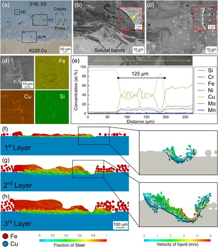
The EDX mapping surrounding a representative crack is illustrated in (d). An enrichment of Cu and Si is observed along the crack with a depletion of Fe. These cracks are believed to be hot cracks [Citation32], which occur during solidification as the low-melting elements, e.g. Cu, partition into the vulnerable regions (possibly grain boundaries of 316L SS). Previous research on laser welding of steel over copper plates suggests that such cracks are highly sensitive to the overall Cu content within steel, which typically occurs when the Cu volume fraction is above 10% [Citation33]. The transition zone size of the Fe/Cu interface is estimated by using the EDX line scan, (e). On average, the transition zone has a dimension of about 125 μm, which is more than twice the value of the powder layer thickness of 50 μm.
Multi-layer CFD simulations were carried out to understand the elemental transition across the Fe/Cu interface during the LPBF process, (f–h). For the first layer of melting 316L SS powders on the K220 Cu alloy, the melt pool only has a small depth of ∼50 μm, due to the high thermal conductivity and low laser absorptivity of Cu which dissipates away much of the laser input energy, (f). Most of the elemental mixing occurred along the melt pool borders, as indicated by the green-colored belts which indicate regions with equal volume fractions for both materials. The velocity of liquid flows within the melt pool is slow, mostly around 1 m/s, indicated by the blue/green arrows in the inset on the right-hand side of (f). It is postulated that such a slow liquid flow rate is insufficient to transport and mix the two alloys effectively. Upon the deposition of the second layer, the melt pool depth increases to ∼115 μm, due to higher heat retentions resulting from the reduced thermal conductivity of the material mixers. Consequently, the liquid within the melt pool is also moving at a faster speed (up to about 5 m/s), encouraging material transportation and hence mixing, evidenced by the larger green region, (g). During the melting of the third layer, the melt pool depth further increases to about 150 μm, but the liquid velocity remains almost the same (not shown here). By the end of the third layer’s fabrication, the transition zone between the two alloys is mostly stabilised, (h). Such an observation agrees with our previous experimental results, that the transition zone spans across a length, of more than two layers of deposited powders, (e).
Compared to the Fe/Cu interface, the Cu/Fe interface has a more extended and more homogeneous transition zone, (a). At the bottom of this transition zone, a sharp interface between the K220 Cu and 316L SS is present, (b). Above the fusion line, tiny spherical Fe particles are found to be homogenously distributed within the Cu matrix. An image analysis shows that the Fe content above the fusion line is about 42.7 vol.%, suggesting almost an equal mixing between the two materials. Infiltration of Cu into the grain boundaries of 316L SS is discerned below the melt pool border, indicated by the white arrows. Similar to the Fe/Cu interface from (b), a Fe-precipitate-free zone is present immediately above the melt pool border, indicated by the red box within (b). On top of the Cu/Fe transition zone, black Fe particles slowly disappeared and columnar grains began to emerge, (c). Within individual Fe particles inside the transition zone, their composition is not uniform, and bright Cu precipitates are often observed, i.e. the red inset within (c). During the solidification of Fe-enriched particles, the minor Cu content trapped within does not have sufficient time to escape and remains inside as isolated droplets [Citation34].
Figure 3. K220 Cu over 316L SS interface. (a) OM image of the Cu/Fe interface. Enlarged SEM image of the (b) top and the (c) bottom of the Cu/Fe interface’s transition zone. (d) EDX mapping of a representative crack within the 316L SS region. (e) EDX line scan across the transition zone. (f) CFD simulations for the keyhole melt pool morphology, and the inset illustrates the fluid flow velocities within the melt pool.
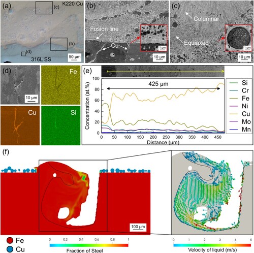
The cracks present near the Cu/Fe interface are much smaller and fewer in number than those close to the Fe/Cu interface, (a) and (a). Despite both types of cracks only occur within the 316L SS region and their chemical compositions are alike ((d) and (d)), the mechanisms of their initiations are believed to be different. For the Fe/Cu interface, cracks occur during solidification, in which complete melting of the 316L SS powders is a prerequisite for its interfacial bonding. During the melting stage, the melted Cu elements from below enter the melt pool via flow convection. Subsequently, the Cu elements preferentially partition into the grain boundaries during solidification, which causes hot cracking [Citation35]. In contrast, for the Cu/Fe interface, the cracked 316L SS parts do not experience full melting, as fully melted steels would have been transported into the melt pool and mixed with liquid Cu, only the grain boundaries are partially melted. Liquid Cu permeates into these melted grain boundaries and causes cracking, which is often referred to as hot-shortness [Citation36], (b and d).
Residual stress is the major factor accounting for the difference in crack sizes between these two horizontal interfaces. There is a linear relationship between the cooling temperature range and the residual stress amount [Citation37]. The complete melting of 316L SS at the Fe/Cu interface thus experiences more residual stress than the partially melted 316L SS at the Cu/Fe interface, as the former interface has a longer cooling temperature range from the melting point to room temperature. In addition, Cu has a much higher thermal conductivity than steel (200 vs. 35 kgms−3K−1), making the cooling rate experienced by the Fe/Cu interface larger than that of the Cu/Fe interface, further aggregating the residual stress difference [Citation38]. The Fe/Cu therefore has larger cracks and a higher number density. The transition zone for the Cu/Fe interface spans across a distance of around 425 μm, (e), making it roughly 3.4 times larger than the Fe/Cu transition zone, (e).
A different melt pool morphology, i.e. keyhole mode, is observed when depositing K220 Cu on 316L SS, (f). Due to the lower thermal conductivity and higher laser absorptivity of 316L SS, the energy input to melt K220 Cu is sufficiently high to create a deep melt pool near the Cu/Fe interface. Under the combined influence of vapour pressure and laser reflection, keyhole melt pool thus forms [Citation39]. When the melt pool reaches stabilisation, it has a depth of about 540 μm and a width of around 600 μm. The depth of the melt pool qualitatively agrees with the Cu/Fe transition zone size of 425 μm, and is about 3.6 times deeper than the stabilised melt pool at the Fe/Cu interface. Keyhole pores are detected within the simulated melt pool, as trapped gas bubbles do not have sufficient time to escape during cavity collapse [Citation40], and corresponding experimental observation of keyhole pores are highlighted in (d). Unlike the melt pool at the Fe/Cu interface, where liquid mostly flows parallel to the melt pool border away from the laser-material interaction point ((f) and (g)); circular vortex is present within the melt pool at the Cu/Fe interface, (f). On average, the fluid velocity is around 3 m/s, much higher than the 1 m/s experienced at the Fe/Cu interface, (f). Additionally, this circular motion created by the keyhole-mode melting contributes a beneficial ‘mixing’ effect, similar to those rheomixing processes [Citation41], which yields a more refined and homogenous microstructure, (b and c).
Most large defects that occurred near the 316L SS and K220 Cu side-by-side vertical interface, (c). When transitioning from K220 Cu to 316L SS, large pores and cracks are detected, (a). Chemical heterogeneity is a common sight, as reflected by the enlarged views in (a1–a3), where bright regions are Cu and dark areas are Fe. Image analysis shows that (a3) has about 37.4 vol.% of Cu, slightly lower than the 42.7 vol.% from (b). Yet, due to the different processing conditions, their chemical distributions are vastly different.
Figure 4. 316L SS and K220 Cu side-by-side vertical interface. (a) A montage of SEM images showing the morphology of various defects and chemical heterogeneities near the vertical interface. CFD simulations of the melt pool size and liquid flow velocities for 316L SS and K220 Cu material mixers with (b) 20 vol.%, (c) 50 vol.%, and (d) 80 vol.% K220 Cu.
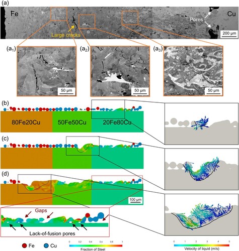
Reports of such LPBF-built multi-material vertical interfaces are scarce, as their production requires special hardware set-ups. For the few studies which examined these vertical interfaces, large defects were always present [Citation27,Citation28]. Schneck et. al. attributed the crack formation to material contamination [Citation27] and Meyer et. al. attributed it to the anisotropic nature of the LPBF process [Citation28]. Contrary to the previous studies, we believe these cracks result from improper processing conditions employed. It is challenging to avoid powder mixing during the spreading of two different powders, due to the excellent flowability of these precursor powder feedstocks. One set of processing parameter would not be optimised for the entire material transition zone [Citation26].
CFD simulations incorporating three different powder mixing ratios were conducted for illustration, and each mixer has a Cu content of 20, 50 and 80 vol.%, respectively, (b–d). As the laser moves from right to left (decreasing Cu content), the melt pool depth increases from 46, to 107 and 130 μm sequentially. Despite the change in melt pool size, the fluid velocities within the melt pools of these scenarios are relatively small, with an average value of around 1 m/s. The slow liquid flow is insufficient to create proper material mixing prior to solidification, which is believed to be the reason for the large segregation phenomenon observed in (a1–a3). For the simulated powder mixer containing 80 vol.% of Cu, lack-of-fusion pores and gaps are present after solidification, highlighted by the red-box inset at the bottom of (d). This observation agrees to the experimental results, in which large pores are present in the Cu-rich steel region near the vertical interface ((d) and (a)).
Among the three different interfaces presented above, the vertical interface poses the greatest challenge to the fabrication of multi-materials with high structural integrity via the LPBF method. Despite it being an integral part of the realisation of truly three-dimensional multi-material production, relevant research efforts are limited [Citation27,Citation28]. The experimental and CFD simulation results in this study have demonstrated the beneficial role of keyhole-mode melting towards material mixing and microstructure refinement, . The adoption of such a keyhole melting strategy thus holds the key to eradicating those large segregation-induced defects occurred near the vertical interface, (d).
Here, a laser parameter optimisation approach for the vertical interface of LPBF-multi-material fabrications is presented below. The mechanism for this method is formulated based on the experimental observation from a large set of materials under different laser irradiation conditions. By correlating the keyhole features with the input laser parameters, the following equation is proposed, based on the keyhole stability factor () [Citation42]:
(1)
(1) where
is the laser absorptivity,
is the laser power,
and
are the liquidus and substrate temperatures,
is the density,
is the heat capacity,
is thermal diffusivity,
is the laser scanning speed and
is the laser radius. Past experimental results indicate that conventional laser melting and keyhole-mode melting typically possess a melt pool depth to laser diameter ratio of about 1 and 2, respectively [Citation39]. These conditions roughly correspond to a
value of 6 and 12, based on the proposed relationship from [Citation42]. By fixing either
or
, we could then obtain the desired laser processing conditions which could enable keyhole melting near the defect susceptible vertical interface.
In the current study, ‘rule of mixtures’ is adopted for the mixed compositions to estimate their relevant properties to be used in Equation (1). Besides those available data in Table S1, and
for 316L SS and K220 Cu are taken as 0.34 vs 0.12, and 6.97 × 10⁻⁶ vs 5.78 × 10⁻⁵ m2s−1 respectively.
is 373 K and
is 40 μm. When fixing the laser scanning speed as 550 mm/s, which is the default value used for 316L SS fabrications here, the required laser power to establish a keyhole melt pool is illustrated by the blue line (
) in (a). The red line (
) represents the threshold, below which the depth of the melt pool is smaller than the laser diameter, making fluid circulation and material mixing within melt pools extremely difficult.
Figure 5. Processing parameter selection maps for the vertical interface between 316L SS and K220 Cu. (a) The required laser power, and (b) the desired laser scanning speed, for different types of material mixing with respect to various K220 fractions. The red and blue curves represent the corresponding processing parameters with the keyhole stability factor Ke = 6 and Ke = 12, respectively.
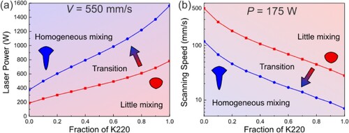
It is found that the required laser power does not follow a linear relationship as the composition changes, which agrees to previous experimental results [Citation25]. In general, more energy input is needed when the Cu content within the material mixture increases, to maintain the same melt pool morphology. The value required for the formation of keyhole melt pools is the smallest for pure 316L SS (375 W) and the largest for pure K220 Cu (1563 W). For a material mixture containing an equal amount of 316L SS and K220 Cu, an 888 W laser power is needed. These values far surpass the upper threshold of most laser units available on the current commercial LPBF machines, which are typically around 400 W. Thus, the adjustment of laser power is not a practical approach for maintaining a keyhole melt pool near the vertical interface between 316L SS and K220 Cu.
An alternative approach is to adjust the laser scanning speeds by keeping the laser power constant, (b). Under this condition, a slower is beneficial for keyhole melt pool generation. When the
value is kept as 175 W, the desired
for keyhole melting condition is 120 mm/s for pure 316L SS, 21 mm/s for the equal-amount material mixture and 7 mm/s for pure K220 Cu. While past literature did demonstrate the practicality of achieving keyhole melt pool in LPBF-built pure Cu using slow scanning speeds (e.g. 50 mm/s in [Citation43]), caution should be exercised in the selection of appropriate powder bed thickness. Gargalis et al. showed that single track instability and denudation could occur when the powder bed thickness is too large (i.e. 100 μm) [Citation44], thus the adjustment of laser scanning speed should be carried out with the consideration of suitable powder thickness. In addition, when the scanning speed is slow, it will unavoidably have a negative impact on the part fabrication rate [Citation45]. Yet, given the small fraction of vertical interfaces within the overall multi-material build, the trade-off between the overall part integrity and small production time increment is deemed to be reasonable.
In conclusion, this study presents the characteristics of three distinct interfaces (Fe/Cu, Cu/Fe and vertical), that are present within the LPBF-built 316L SS and K220 Cu multi-materials. Hot cracks (<50 μm in length) are discerned within the 316L SS parts along both the Fe/Cu and Cu/Fe horizontal interfaces. Between these two, the Cu/Fe interface has smaller and fewer cracks, due to the limited Cu infiltration into the partially melted grain boundaries of 316L SS. The vertical interface shows the greatest vulnerability to defect formation, ascribed to the need for composition-dependent laser processing parameters. A simple parameter optimisation method to create keyhole melt pools is illustrated to aid future LPBF production of vertical interfaces within multi-materials.
Acknowledgements
This work was also supported by the A*STAR Computational Resource Centre through the use of its high-performance computing facilities.
Disclosure statement
No potential conflict of interest was reported by the author(s).
Data availability statement
The data that support the findings of this study are available from the corresponding author, Z. Sun, upon reasonable request.
Additional information
Funding
References
- DebRoy T, Wei HL, Zuback JS, et al. Additive manufacturing of metallic components – Process, structure and properties. Prog Mater Sci. 2018;92:112–224.
- Dong Z, Han C, Zhao Y, et al. Role of heterogenous microstructure and deformation behavior in achieving superior strength-ductility synergy in zinc fabricated via laser powder bed fusion. Int J Extrem Manuf. 2024;6.
- Kang SG, Gainov R, Heußen D, et al. Green laser powder bed fusion based fabrication and rate-dependent mechanical properties of copper lattices. Mater Des. 2023;231:112023.
- Sun Z, Tsai SP, Konijnenberg P, et al. A large-volume 3D EBSD study on additively manufactured 316L stainless steel. Scr Mater. 2024;238:115723.
- Sun Z, Sun B, Soh V, et al. Laser powder bed fusion of crack-susceptible stainless maraging steel undergoing solid-state phase transformations. Acta Mater. 2024;263:119534.
- Roscher M, Sun Z, Jägle EA. Designing Al alloys for laser powder bed fusion via laser surface melting: Microstructure and processability of 7034 and modified 2065. J Mater Process Technol. 2024;326:118334.
- Sun Z, Soh V, Lee C, et al. Effects of carbon content on precipitate evolution and crack susceptibility in additively manufactured IN738LC. MSAM. 2024;3:2264.
- Wei S, Zhao Y, Zhang B, et al. Mesoscopic chemical heterogeneities in laser powder bed fused CoCrMo and Ni mixed powders and their effect on the mechanical properties. Mater Sci Eng A. 2023;888:145795.
- Wei S, Zhao Y, Li S-H, et al. Laser powder bed fusion of a Cu-Ni-Al alloy using the compositional grading approach. Scr Mater. 2023;231:115441.
- Zhang Y, Groden C, Nyberg E, et al. W7Ni3Fe-Ti6Al4V bimetallic layered structures via directed energy deposition. Virtual Phys. Prototyp. 2023;18:e2137048.
- Groden C, Champagne V, Bose S, et al. Inconel 718-CoCrMo bimetallic structures through directed energy deposition-based additive manufacturing. Mater Sci Add Manuf. 2022;1:18.
- Sing SL, Huang S, Goh GD, et al. Emerging metallic systems for additive manufacturing: In-situ alloying and multi-metal processing in laser powder bed fusion. Prog Mater Sci. 2021;119:100795.
- Nazir A, Gokcekaya O, Md Masum Billah K, et al. Multi-material additive manufacturing: A systematic review of design, properties, applications, challenges, and 3D printing of materials and cellular metamaterials. Mater Des. 2023;226:111661.
- Wei C, Liu L, Gu Y, et al. Multi-material additive-manufacturing of tungsten - copper alloy bimetallic structure with a stainless-steel interlayer and associated bonding mechanisms. Addit Manuf. 2022;50:102574.
- Schmidt A, Jensch F, Härtel S. Multi-material additive manufacturing-functionally graded materials by means of laser remelting during laser powder bed fusion. Front Mech Eng. 2023;18:49.
- Wei C, Li L, Zhang X, et al. 3D printing of multiple metallic materials via modified selective laser melting. CIRP Ann. 2018;67:245–248.
- Tan C, Chew Y, Bi G, et al. Additive manufacturing of steel–copper functionally graded material with ultrahigh bonding strength. J Mater Sci Technol 2021;72:217–222.
- Zhang W, Zhang B, Xiao H, et al. A layer-dependent analytical model for printability assessment of additive manufacturing copper/steel multi-material components by directed energy deposition. Micromachines (Basel). 2021;12:1394.
- Ramon J, Basu R, Vander Voort G, et al. A comprehensive study on solidification (hot) cracking in austenitic stainless steel welds from a microstructural approach. Int J Press Vessel Pip. 2021;194:104560.
- Liu ZH, Zhang DQ, Sing SL, et al. Interfacial characterization of SLM parts in multi-material processing: Metallurgical diffusion between 316L stainless steel and C18400 copper alloy. Mater Charact. 2014;94:116–125.
- Chen J, Yang Y, Song C, et al. Interfacial microstructure and mechanical properties of 316L /CuSn10 multi-material bimetallic structure fabricated by selective laser melting. Mater Sci Eng A. 2019;752:75–85.
- Zhang X, Sun C, Pan T, et al. Additive manufacturing of copper – H13 tool steel bi-metallic structures via Ni-based multi-interlayer. Addit. Manuf. 2020;36:101474.
- Zhang X, Pan T, Chen Y, et al. Additive manufacturing of copper-stainless steel hybrid components using laser-aided directed energy deposition. J Mater Sci Technol. 2021;80:100–116.
- Zhang B, Zhang W, Xiao H, et al. QCr0.8 Cu alloy /S06 stainless steel bimetal structure via In718 multi-interlayer fabricated by laser powder hybrid additive manufacturing. J. Mater. Res. Technol. 2023;24:1034–1042.
- Rankouhi B, Jahani S, Pfefferkorn FE, et al. Compositional grading of a 316L-Cu multi-material part using machine learning for the determination of selective laser melting process parameters. Addit Manuf. 2021;38:101836.
- Yadav S, Paul CP, Rai AK, et al. Elucidating laser directed energy deposition based additive manufacturing of copper-stainless steel functionally graded material: Processing and material behavior. J Manuf Process. 2023;92:107–123.
- Schneck M, Horn M, Schindler M, et al. Capability of multi-material laser-based powder bed fusion—development and analysis of a prototype large bore engine component. Metals (Basel). 2022;12:44.
- Meyer I, Oel M, Ehlers T, et al. Additive manufacturing of multi-material parts – Design guidelines for manufacturing of 316L/CuCrZr in laser powder bed fusion. Heliyon. 2023;9:e18301.
- Zhongji S, Leong S, Kai C, et al. Hopper for Powder Bed Fusion Additive Manufacturing. 2017.
- Tang C, Yao L, Du H. Computational framework for the simulation of multi material laser powder bed fusion. Int J Heat Mass Transf. 2022;191:122855.
- Munitz A. Metastable liquid phase separation in tungsten inert gas and electron beam copper/stainless-steel welds. J Mater Sci. 1995;30:2901–2910.
- Noecker FF, DuPont JN. Microstructural development and solidification cracking susceptibility of Cu deposits on steel: Part I. J Mater Sci. 2007;42:495–509.
- Rinne J, Seffer O, Nothdurft S, et al. Investigations on the weld metal composition and associated weld metal cracking in laser beam welded steel copper dissimilar joints. J Mater Process Technol. 2021;296:117178.
- Wang CP, Liu XJ, Shi RP, et al. Design and formation mechanism of self-organized core/shell structure composite powder in immiscible liquid system. Appl Phys Lett. 2007;91:1–4.
- Rinne J, Nothdurft S, Hermsdorf J, et al. Investigations on laser welding of dissimilar joints of stainless steel and copper for hot crack prevention. J Laser Appl. 2021;33:1.
- Garza LG, Van Tyne CJ. Surface hot-shortness of 1045 forging steel with residual copper. J Mater Process Technol. 2005;159:169–180.
- Mercelis P, Kruth JP. Residual stresses in selective laser sintering and selective laser melting. Rapid Prototyp J. 2006;12:254–265.
- Zhang Y, Yi Y, Huang S, et al. Influence of quenching cooling rate on residual stress and tensile properties of 2A14 aluminum alloy forgings. Mater Sci Eng A. 2016;674:658–665.
- King WE, Barth HD, Castillo VM, et al. Observation of keyhole-mode laser melting in laser powder-bed fusion additive manufacturing. J Mater Process Technol. 2014;214:2915–2925.
- Sun Z, Ma Y, Ponge D, et al. Thermodynamics-guided alloy and process design for additive manufacturing. Nat Commun. 2022;13.
- Fang X, Ji S, Fan Z. Processing of immiscible metallic alloys by rheomixing process. Mater Sci Technol. 2001;17:837–842.
- Gan Z, Kafka OL, Parab N, et al. Universal scaling laws of keyhole stability and porosity in 3D printing of metals. Nat Commun. 2021;12.
- Speidel A, Wadge MD, Gargalis L, et al. The interaction of volatile metal coatings during the laser powder bed fusion of copper. J Mater Process Technol. 2022;299:117332.
- Gargalis L, Ye J, Strantza M, et al. Determining processing behaviour of pure Cu in laser powder bed fusion using direct micro-calorimetry. J Mater Process Technol. 2021;294:117130.
- Sun Z, Tan X, Tor SB, et al. Selective laser melting of stainless steel 316L with low porosity and high build rates. Mater Des. 2016;104:197–204.