
 ?Mathematical formulae have been encoded as MathML and are displayed in this HTML version using MathJax in order to improve their display. Uncheck the box to turn MathJax off. This feature requires Javascript. Click on a formula to zoom.
ABSTRACT
This study investigates the introduction of ultrasonic impact treatment (UIT) during the wire arc additive manufacturing process to refine the microstructure and enhance the properties of 18Ni-300 maraging steel components. It was found that interlayer ultrasonic impact treatment (I-UIT) and synchronous ultrasonic impact treatment (S-UIT) applied to the deposited metal can refine the grains, alter grain growth orientation, and reduce anisotropy. At the top of the formed component, compared to directly deposited specimens, significant grain refinement and the appearance of a 20μm nanocrystalline zone were observed in I-UIT-WAAM samples, while S-UIT-WAAM samples similarly exhibited the effects of ultrasonic impact, with a deeper nanocrystalline zone of 230μm. In the middle of the formed component, due to subsequent remelting and heating effects, the ultrasonic effect was weakened, resulting in the disappearance of the nanocrystalline zone. Compared to I-UIT-WAAM S-UIT-WAAM samples samples, S-UIT-WAAM samples showed better ultrasonic assistance effects due to the ultrasonic impact on the molten pool, with significantly reduced austenite content, average grain size, and texture density. In terms of mechanical properties, for S-UIT-WAAM samples, the horizontal tensile strength was 1401.3 ± 57.6 MPa, and the vertical tensile strength was 1327 ± 9.5 MPa. Compared to directly deposited specimens, the horizontal and vertical tensile strengths of I-UIT-WAAM samples increased by 14.6% and 11.3%, respectively.
1. Introduction
Wire arc additive manufacturing (WAAM) [Citation1–3] is an advanced manufacturing process that employs an electric arc as the heat source to melt metal wire, depositing it layer by layer to create three-dimensional metal components. This technology is renowned for its high deposition rates, it can manufacture high density of formed part, and unrestricted part sizes due to its open manufacturing environment. Primarily, it offers significant advantages in terms of cost-efficiency, speed, and scalability for the production of large and geometrically complex components [Citation4]. Maraging steel [Citation5,Citation6], on the other hand, is a specialised type of ultra-high-strength steel characterised by its Fe-Ni matrix and ultra-low carbon content. It also incorporates various alloying elements such as Co, Ti, Al, and Mo, which contribute to its age-hardening properties and formation of intermetallic compounds, including laves phase phases like Ni3Al, Ni3Ti, and Fe2Mo [Citation7,Citation8]. These unique compositional features endow maraging steel with exceptional mechanical properties, including high tensile strength and good ductility [Citation9,Citation10], making it an ideal material for demanding applications in aerospace, automotive, and defense industries [Citation11–13]. Therefore, the integration of WAAM with maraging steel presents a substantial opportunity for engineering applications, as it combines the cost-effective and rapid manufacturing capabilities of WAAM with the superior mechanical properties of maraging steel.
Xiangfang Xu et al. [Citation14] observed that due to transient thermal cycling, the microhardness and tensile strength of as-deposited alloy decrease from bottom to top, leading to uneven formation of partial aging and intermetallic compounds along the build direction. As-deposited alloys exhibit higher strength than forged alloys under solute conditions, but not under aging conditions, attributed to the less pronounced aging response of microstructures characterised by low-angle columnar grains and the presence of residual and reverted austenite. Daren Peng et al. [Citation15] found low durability of parts made of 18Ni250 maraging steel via wire arc additive manufacturing due to fatigue crack propagation caused by interactions between material surface roughness and surface fracture defects. Zhang et al. [Citation16] studied the influence of different heat inputs on the microstructure and mechanical properties of 18Ni300 maraging steel. The results indicate that low heat input contributes to the formation of {110} < 001> Goss texture, while high heat input contributes to the formation of {100} < 001> Cube texture, with the poorest mechanical properties. Xu et al. [Citation17] discovered through WAAM process with interlayer cold rolling technique that columnar grains evolve into numerous large-angle grains during rolling and subsequent thermal cooling processes. After aging, the ultimate tensile strength of the samples significantly increased from 1410 MPa to 1750MPa, reaching the level of conventional processing. Collectively, these studies highlight the intricate relationships between processing parameters, microstructure, and mechanical properties in wire arc additive manufacturing of maraging steel. While significant progress has been made in understanding these relationships, there remains a critical need for further optimisation of the additive manufacturing process to fully harness the exceptional properties of maraging steel.
Currently, research shows that ultrasonic-assisted techniques have various applications in additive manufacturing, such as ultrasonic shot peening, ultrasonic surface rolling, and ultrasonic impact treatment (UIT). Wang et al. [Citation18] studied the effect of ultrasonic impact treatment on the microstructure and mechanical properties of WAAM 2219 aluminium alloy. The results indicate that UIT can refine grain size, reduce porosity, increase dislocation density, improve surface residual stress, and ensure the uniform distribution of precipitated phases in the matrix, effectively enhancing the mechanical properties of WAAM components. Diao et al. [Citation19] employed a UIT system synchronised with a CMT welding gun to apply ultrasonic vibration ahead of the deposition layer. It was found that ultrasonic assistance can refine grains, enhance grain boundary strengthening, and promote recrystallization to reduce dislocation density and texture density. Gou et al. [Citation20] used three-axis ultrasonic peening treatment (UPT) to investigate the cold metal transfer additive manufacturing of Ti-6Al-4 V thin-walled structures, revealing that UPT can refine large columnar prior-β grains and secondary-α grains, and reduce the percentage of anisotropy in tensile properties. Additionally, Chen et al. [Citation21] discussed the possibility of integrating surface enhancement (SE) into additive manufacturing. They introduced the improvement effects of SE technology on additive manufacturing parts from aspects such as microstructure, defects, residual stress, mechanical properties, and chemical properties, and proposed a closed-loop quality control framework integrating interlayer UIT into the directed energy deposition (DED) process. Wang et al. [Citation22] analysed the microstructure and mechanical properties of DED-UIT 304 stainless steel using layer-by-layer ultrasonic impact treatment. The results showed a reduction in pore quantity and a decrease in average diameter by 62.4%. After UIT, the average hardness increased from 126.3 HV0.2 to 171.3 HV0.2, with samples within the top 1000 µm of the DED-UIT exhibiting higher average hardness than samples at other locations. The average yield strength increased from 368.9 MPa to 401.8 MPa, and the average ultimate tensile strength (UTS) also increased. The average elongation increased from 40.7% to 46.9%.
In summary, using ultrasonic impact treatment can refine the grains, reduce defects, and enhance the performance of additively manufactured components. However, the application of ultrasonic-assisted additive manufacturing for optimising the properties of maraging steel is relatively rare. Many studies have only introduced ultrasonic impact assistance in wire arc additive manufacturing processes to investigate its effects. In our subsequent research, we will conduct comparative experiments to further analyze the role of ultrasonic impact. Therefore, this paper introduces ultrasonic impact into the process of arc additive manufacturing of maraging steel, analyzes its influence on the microstructure and mechanical properties of the additively manufactured samples, and provides theoretical support for the efficient and high-quality manufacturing of maraging steel.
2. Experimental methodology
2.1. Ultrasonic impact assisted wire arc additive manufacturing system
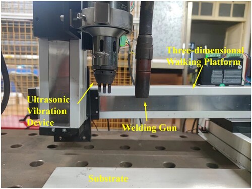
This experiment utilises a robotic cold metal transfer (CMT) based wire arc additive manufacturing equipment, as shown in . It mainly consists of a Fronius CMT 4000 Advanced welding power supply, a CMTVR 1550 wire feeding system, a six-axis IRB1410-5/1.45 robot produced by ABB in Switzerland, and an IRC5 robot control cabinet. The ultrasonic impact device in this experiment is composed of an LZ-2000 power supply and an ultrasonic gun. The three-dimensional walking platform is made up of four FSL80 lead screw sliding tables and is controlled by a computer control device. The ultrasonic impact device is fixed to the lead screw sliding table via bolts, and the three-dimensional walking movement of the ultrasonic impact device is achieved through the movement of the lead screw sliding tables in three directions. During the wire arc additive manufacturing process, the ultrasonic impact device is set to move at the same speed as the welding torch, maintaining a distance of 50-90 mm between the centre positions of the ultrasonic impact head and the welding torch, as shown in . During the experimental process, we maintained a distance of 70 mm between the position of ultrasonic impact and the centre of the molten pool.
Figure 1. Schematic diagram of ultrasonic impact assisted wire arc additive manufacturing test system.
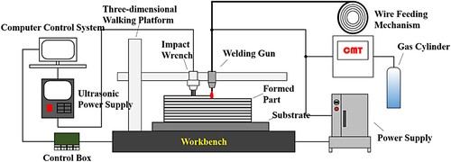
Figure 2. Photograph of maraging aging steel in ultrasonic impact assisted wire arc additive manufacturing.
2.2. Experimental materials and procedures
In this experiment, 18Ni-300 maraging steel welding wire with a diameter of 1.00 mm was used as the deposited material, and a 450 × 200 × 10 mm 316L stainless steel plate was used as the substrate material. The compositions of the wire and substrate materials used are shown in .
Table 1. Chemical composition of wire and substrate materials (mass fraction, wt%).
This experiment employed the CMT process, the wire feeding speed of 8 m/min, arc travel speed of 8 mm/s, pure Ar as the shielding gas with a flow rate of 25L/min, a nozzle-to-substrate distance of 15 mm, and a wire extension length of 10 mm. A single-pass, multi-layered deposition part with dimensions of 160 mm in length and 70 mm in height was deposited, and ultrasonic impact was immediately applied after welding in the I-UIT-WAAM process. The ultrasonic impact process parameters are shown in .
Table 2. Ultrasonic impact process parameters.
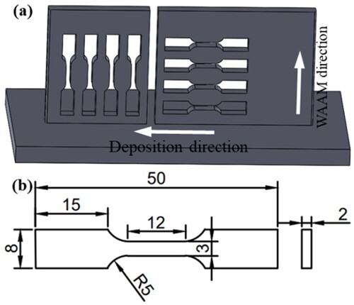
To investigate the influence of various ultrasonic impact treatments on the microstructure and mechanical properties of wire arc additive manufactured components, this study conducted a series of controlled experiments on maraging steel using three different additive manufacturing methods: no ultrasonic impact treatment (NO-UIT-WAAM), interlayer ultrasonic impact treatment (I-UIT-WAAM), and synchronous ultrasonic impact treatment (S-UIT-WAAM), as schematically represented in . However, this study does not consider the effect of interlayer temperature distribution because ultrasound was applied immediately after welding in the I-UIT-WAAM case. For each method, a single-pass multi-layer sample with dimensions of 160 mm in length and 70 mm in height was fabricated, as shown in . Macroscopic examination revealed that the samples exhibited good surface formation, indicating that the ultrasonic impact treatments did not adversely affect their morphology. Subsequently, to further analyze the material properties, specific sampling locations were selected, and tensile specimens were prepared according to standardised dimensions, as outlined in . This ensures a rigorous and systematic approach to evaluating the effects of ultrasonic impact treatments on the mechanical behaviour of the wire arc additive manufactured maraging steel.
Figure 3. Comparison of three different additive manufacturing methods.
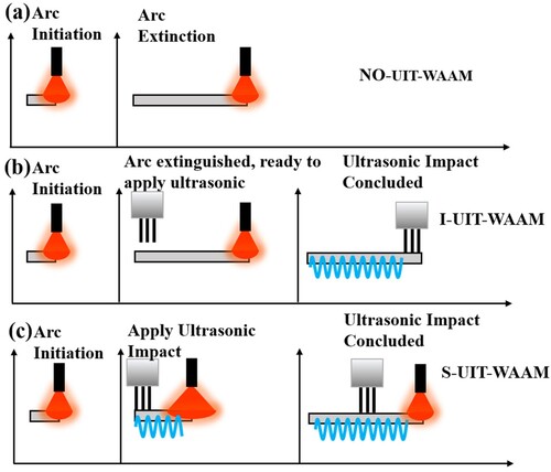
Figure 4. Macroscopic morphology of single-pass multi-layer components.
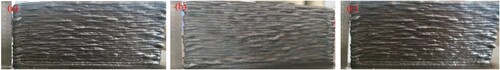
Figure 5. 18Ni-300 steel single-pass multi-layer components.
3. Results and analysis
3.1. Microstructure of the formed components
3.1.1. Overall microstructural characteristics of single-pass multi-layer components
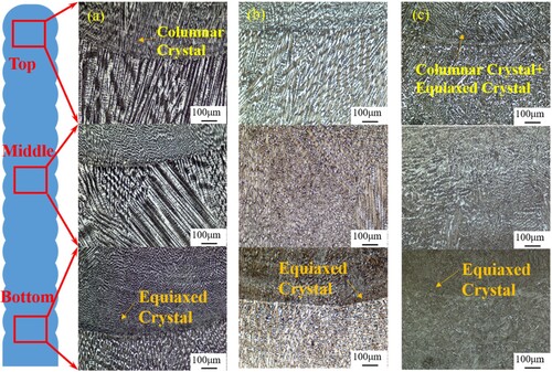
The microstructures of the specimens subjected to three different ultrasonic application methods are shown in . The microstructure at the bottom of the I-UIT-WAAM specimen is similar to that of the NO-UIT-WAAM specimen. In the middle and top positions, columnar grains are observed, with their growth direction perpendicular to the substrate position. However, the length of columnar grains in the I-UIT-WAAM specimen is significantly shorter than that in the NO-UIT-WAAM specimen. This change can be attributed to the mechanism of ultrasonic impact treatment for two reasons: Firstly, the molten pool of the I-UIT-WAAM specimen has already started solidifying, and under the influence of the ultrasonic impact load, the contact part undergoes significant plastic deformation [Citation23], leading to obvious inhibition of columnar grain growth. Secondly, ultrasonic impact treatment affects the recrystallization of solid metal structures. In the I-UIT-WAAM process, although the solid deposition layer is mainly influenced by ultrasonic impact after deposition, the sample remains at high temperature. Due to the ultrasonic impact, recrystallization still occurs in the solid deposition layer [Citation19], resulting in a decrease in the length of columnar grains and grain refinement. At the bottom position of the S-UIT-WAAM specimen, below the fusion line, there are columnar grains, and their grain growth is similar to the microstructure of the single-layer top. In the microstructure above the fusion line in the top region, compared to the microstructure of I-UIT-WAAM, there are more pronounced equiaxed grains. Here, not only does the same ultrasonic mechanism as in I-UIT-WAAM occur, but also, because the ultrasonic impact directly affects the molten pool, the range of ultrasonic action within the molten pool is greater, further suppressing the growth of columnar grains. Additionally, due to slower cooling rates, the equiaxed grain structure gradually grows into a combination of equiaxed and columnar grains.
Figure 6. Microstructure of different regions of wire arc additively manufactured 18Ni-300 steel (a) NO-UIT-WAAM (b) I-UIT-WAAM (c) S-UIT-WAAM.
3.1.2. Microstructural characteristics of the top layer of single-pass multi-layer components
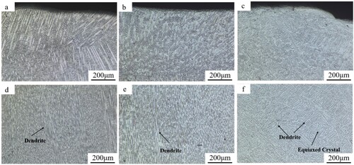
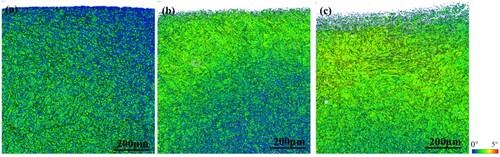
(a,d) depict the top layer microstructure of the Without UIT specimen. Due to direct contact between the deposition layer surface and the arc space, the heat of the arc is transferred within the arc space, resulting in a small temperature gradient and the formation of typical coarse columnar grain structure. The columnar grains represent the direction of maximum cooling rate, i.e. the direction of WAAM. In (b,e), the top layer exhibits short, stout columnar grain structure. Direct contact with the ultrasonic impact pin induces changes not only in the top layer microstructure but also in the formation of a distinct plastic deformation zone on the top layer surface after impact application. The grains in this region are significantly refined, forming a nanocrystalline zone [Citation24], approximately 20μm in size. (c,f) display the top layer microstructure of the S-UIT specimen. The microstructure undergoes significant changes, with alteration in grain growth direction and the formation of a distinct nanolayer of approximately 230μm due to ultrasonic impact. The size of the nanocrystalline zone increases notably. This is attributed to the temperature at the interaction site between the ultrasonic impact pin and the corresponding deposition layer. In the I-UIT-WAAM specimen, the ultrasonic impact is applied after arc extinguishing, resulting in lower temperature and poorer thermal plasticity at the deposition layer site. Consequently, the nanocrystalline zone formed is smaller. In contrast, in the S-UIT-WAAM specimen, the deposition layer location is still subjected to the heat of the arc during the WAAM process, leading to higher temperature and better thermal plasticity, resulting in a larger nanocrystalline zone.
Figure 7. Microstructural morphology of the top deposition layer in ultrasonic impact assisted wire arc additive manufacturing of 18Ni-300 steel.
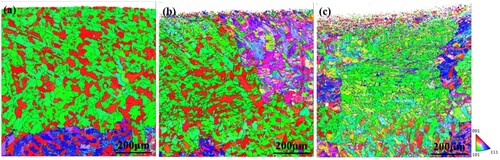
shows the IPF maps of the top deposition layer in wire arc additive manufacturing of 18Ni-300 maraging aging steel. It can be observed that the grain orientation at the top of the NO-UIT-WAAM specimen is mainly in the <101 > and <001 > directions. The overall grain orientation of the I-UIT-WAAM specimen is similar to that of the NO-UIT-WAAM specimen. However, due to the effect of the ultrasonic impact load being in the same direction as the WAAM direction, there is a change in grain orientation in the fine grain zone at the top deposition layer. In the S-UIT-WAAM specimen, the grain orientation is mainly in the <101 > direction, with almost no grain orientation in the <001 > direction. This indicates that the growth of grains in the <001 > direction is suppressed by the effect of ultrasonic impact.
Figure 8. Inverse pole figure (IPF) maps of the top deposition layer in ultrasonic impact assisted wire arc additive manufacturing of 18Ni-300 steel.
The KAM maps allow for the quantitative calculation of geometric dislocation density, reflecting the uniformity of plastic deformation within the material. A higher KAM value indicates a greater degree of plastic deformation or defect density [Citation25]. From the above figures, it can be observed that the NO-UIT-WAAM specimen exhibits the smallest KAM values, with relatively small values at the top and slightly larger values internally. Conversely, after applying ultrasonic impact, as shown in (b,c), the KAM distribution is opposite to that of the deposited specimen, with significantly larger KAM values at the top position than internally. In the I-UIT-WAAM specimen, the KAM values are relatively large within 0.4μm from the top, indicating significant plastic deformation, while the KAM values decrease deeper into the material, suggesting a reduction in plastic deformation within the internal regions after ultrasonic impact. For the S-UIT-WAAM specimen, the KAM values are consistently large throughout the entire region, indicating a significant plastic deformation zone within 0.8μm. Moreover, the plastic deformation induced by ultrasonic impact penetrates deeper into the material, leading to larger plastic deformation zones, lattice distortions, and the generation of substructures. Therefore, it can be concluded that applying ultrasonic impact effectively increases plastic deformation in the microstructure. However, different ultrasonic impact application methods result in varying extents of plastic deformation zones. The plastic deformation in the S-UIT-WAAM specimen is significantly greater than that in the I-UIT-WAAM specimen. Furthermore, ultrasonic impact leads to an increase in substructures within the material, which plays a crucial role in subsequent interlayer effects.
Figure 9. Kernel average misorientation (KAM) maps of the top of 18Ni-300 steel in ultrasonic impact wire and assisted arc additive manufacturing.
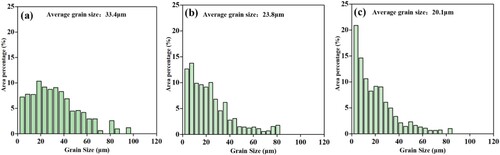
represents the grain statistics of the top deposition layer. It is observed that the average grain diameter is 33.4μm for the direct deposition specimen, 23.8μm for the I-UIT-WAAM specimen, and 20.1μm for the S-UIT-WAAM specimen. Hence, ultrasonic impact improves the grain size of the microstructure, leading to significant grain refinement. Considering grains larger than 60μm as large grains, it can be noted that the proportion of large grains is 11.33% for the direct deposition specimen, 7.20% for the I-UIT-WAAM specimen, and 4.16% for the S-UIT-WAAM specimen. This indicates a more ideal grain refinement effect achieved by ultrasonic impact. It suggests that ultrasonic impact suppresses the formation of large grains in the microstructure.
Figure 10. Grain statistics of the top region in ultrasonic impact assisted additive manufacturing of 18Ni-300 steel (a) NO-UIT-WAAM (b) I-UIT-WAAM (c) S-UIT-WAAM.
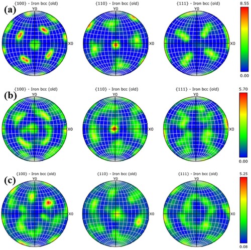
The pole figures of the martensitic matrix are shown in . It can be observed that the maximum density of texture orientation for the direct deposition specimen is 8.55. The I-UIT-WAAM specimen exhibits relatively weaker texture with a maximum density of 5.70, while the S-UIT-WAAM specimen shows even lower texture orientation density, with a maximum density of only 5.25. The pole figure of the NO-UIT-WAAM specimen is nearly symmetrical about the X0 and Y0 axes, indicating the presence of significant texture orientation within the material. In contrast, the orientation distribution of the S-UIT-WAAM specimen appears randomly distributed, suggesting less pronounced texture orientation. Therefore, from the above analysis, it can be inferred that the direct deposition specimen exhibits a significant texture in the top metal layer, while applying ultrasonic impact can suppress the growth of columnar grains in the top microstructure, thereby reducing the preferred orientation and lowering the overall anisotropy.
Figure 11. Pole figures of ultrasonic impact assisted additive manufacturing of 18Ni-300 steel specimens (a) NO-UIT-WAAM (b) I-UIT-WAAM (c) S-UIT-WAAM.
3.1.3. Microstructure characteristics of the middle section in single-pass multi-layered components
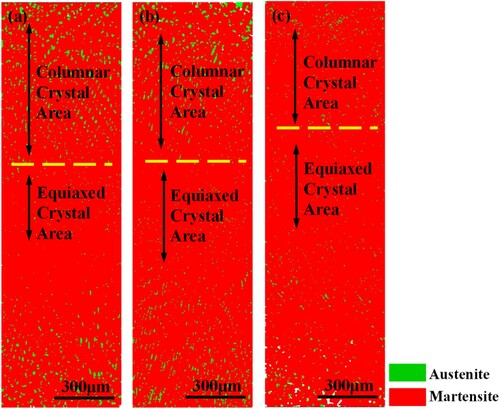
To better understand the effects of the interaction between ultrasonic impact and repeated thermal cycling in the process of wire arc additive manufacturing, the middle section of the single-pass multi-layered components was selected as the observation area. As shown in (a), the upper-middle part of the deposition layer is composed of numerous columnar crystals, with the growth direction of the columnar crystals basically consistent with the deposition direction. Partial equiaxed crystals appear in the lower-middle part of the deposition layer, and as the distance from the top of the previous deposition layer decreases, the number of equiaxed crystals gradually increases while their size significantly decreases, presenting obvious anisotropy overall. During the deposition process, rapid heat exchange occurs when the bottom of the molten pool contacts the previous deposition layer, resulting in the rapid solidification of the liquid metal into uniformly fine equiaxed crystals within an extremely short period. Due to the excessively rapid solidification rate, the orientation of the microstructure is not apparent. However, with the increase in distance from the previous deposition layer, the decrease in heat exchange rate leads to a reduction in solidification rate, causing the temperature gradient direction to align with the deposition direction. This provides sufficient time for directional growth of columnar crystals, resulting in the apparent growth of columnar crystals in the upper-middle part of the deposition layer.
Figure 12. Metallography of the deposited layer in ultrasonic impact-assisted wire arc additive manufacturing of 18Ni-300 steel. (a) NO-UIT-WAAM (b) I-UIT-WAAM (c)S-UIT-WAAM.
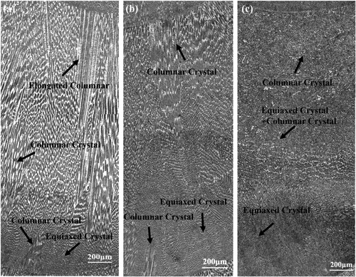
The microstructure of the I-UIT-WAAM sample is shown in (b), characterised by columnar crystals. However, compared to the NO-UIT-WAAM sample, the columnar grain length is significantly shorter, and the grain width is noticeably larger. Due to multiple interlayer thermal cycles, recrystallization occurs, and due to the temperature gradient, the growth direction is perpendicular to the substrate. When the ultrasonic impact needle acts in the same direction as the grain growth direction, the ultrasonic waves suppress the growth of grains along the direction of the ultrasonic field.
The microstructure of the middle section deposition layer of the S-UIT-WAAM sample is shown in (c). The microstructure at the bottom position consists of equiaxed grains and columnar crystals, similar to that of the NO-UIT-WAAM sample. As the distance from the previous layer deposition increases, the grain growth mode changes. This is because the solidification speed of the liquid metal decreases, allowing the ultrasound field to be more effectively transmitted to this position, the dendrites in the initial growth stage are shattered by the ultrasonic field. Additionally, due to the cavitation effect of ultrasound and the enhancement of convection, the temperature of the molten pool increases [Citation26]. The increase in molten pool temperature leads to a decrease in temperature gradient, further promoting an increase in nucleation rate and undercooling. This solidification mode is different from that of the molten pool in NO-UIT-WAAM and I-UIT-WAAM, creating favourable conditions for the formation of fine equiaxed grains. Therefore, grain refinement occurs at this position, and no significant directional preference in grain growth direction is observed.
The austenite content has a significant impact on the plasticity and toughness of 18Ni-300 steel. A certain amount of austenite (<5%) can improve the plasticity and toughness of the material. However, an excess of austenite can compromise the strength and mechanical properties of the material. shows the phase diagram of the samples. Statistical analysis reveals that the austenite content is 4.7% in the NO-UIT-WAAM sample, 4.3% in the I-UIT-WAAM sample, and 1.7% in the S-UIT-WAAM sample. The microstructure of the NO-UIT-WAAM sample exhibits uneven distribution, which is attributed to rapid solidification and repeated heating during the additive manufacturing process. The repeated heating by the arc causes some unstable martensite to transform into austenite, forming reverted austenite. A comparison shows that applying ultrasonic impact treatment can effectively reduce the interlayer austenite content. This is due to the martensitic transformation induced by stress in the austenite phase during the UIT process, this observation is consistent with the findings of Karthi et al. [Citation27] Additionally, different application methods have different effects on the austenite content. In the I-UIT-WAAM sample, ultrasonic impact treatment is applied after the solidification of the weld pool, without significantly altering the microstructure of the metal. Therefore, the austenite content in the I-UIT-WAAM sample is similar to that in the NO-UIT-WAAM sample. In contrast, the ultrasonic field in the S-UIT-WAAM sample can penetrate into the deposition layer and affect the solidification process of columnar crystals, increasing nucleation in the weld pool. Consequently, the austenite content in the S-UIT-WAAM sample is significantly lower than that in the I-UIT-WAAM sample. Furthermore, the formation of austenite is also related to element segregation, which is discussed in detail in Section 3.2 of this chapter.
Figure 13. Phase diagram of wire arc additive manufacturing of 18Ni-300 steel.
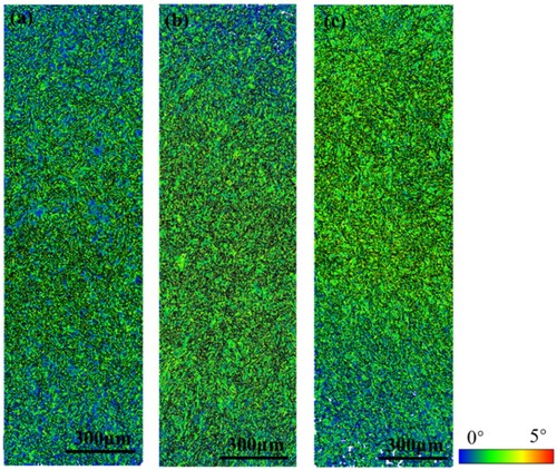
illustrates the Kernel average misorientation map at the central position of the deposition layer. As mentioned earlier, after ultrasonic impact treatment, the KAM values at the top deposition layer position of the specimens significantly increase. This indicates the presence of pronounced plastic deformation zones within the top deposition layer of UIT specimens, characterised by numerous dislocations and substructures. During the deposition process, the arc repeatedly heats the original deposition layer. The plastic deformation zones undergo recrystallization during these repeated heating cycles, leading to a decrease in KAM values within the deposition layer. This may be attributed to deformation or misalignment of crystal structures due to the presence of defects such as grain boundaries and dislocations. Partial recrystallization of some grain boundaries and dislocations occurs during the repeated heating cycles of the arc. However, as shown in , significant regions of high KAM values are still preserved in the S-UIT-WAAM specimen. This preservation may hinder the movement and slip of dislocations at grain boundaries, thereby increasing the material's strength and hardness.
Figure 14. KAM map of wire arc additive manufacturing of 18Ni-300 steel.
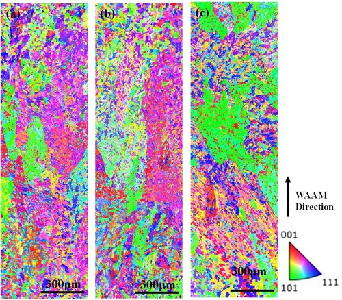
The EBSD analysis was conducted on the central region of the specimen, as shown in . Comparing the IPF map of the central region with the top region shown in , it is evident that there is a greater variety of colours in the IPF map of the central region. These colours represent different crystallographic orientations, indicating recrystallization within the grains due to the effects of repeated thermal cycling. Additionally, the microstructure beneath the melt pool is more susceptible to recrystallization due to direct heating from the overlying deposited layers, resulting in a greater variety of orientations.
Figure 15. Inverse pole figure (IPF) maps of the middle deposition layer in ultrasonic impact assisted wire arc additive manufacturing of 18Ni-300 steel.
As shown in , the average grain diameters of the NO-UIT-WAAM, I-UIT-WAAM, and S-UIT-WAAM specimens are 18.72, 15.14, and 14.41 μm, respectively. Comparing these with the average grain diameter of the top region, it can be observed that the average grain diameter in the central region is significantly smaller. This is attributed to poorer cooling conditions at the top region, leading to the growth of larger grains. It can be observed that the grain sizes of the I-UIT-WAAM and S-UIT-WAAM specimens are refined by 23.6% and 29.9%, respectively. The S-UIT-WAAM specimen exhibits finer grains, and finer grains imply an increased quantity of grain boundaries, which hinder the movement and slip of dislocations during the material's plastic deformation. This makes plastic deformation more difficult, leading to the occurrence of localised plastic deformation and consequently affecting the material's ductility and toughness. Due to reduced temperature gradients, there is sufficient time for the growth of columnar grains in the middle and top regions of the deposition layer. Ultrasonic impact treatment has a significant influence on the growth of columnar grains in this region. Therefore, EBSD data from the columnar grain region are selected for analysis, as shown in . The IPF maps in (a–c) represent the columnar grain region. KAMave is closely related to geometrically necessary dislocations (GNDs). The KAM maps for the columnar grain region are depicted in (a–c). The average K values are 1.452° for the NO-UIT-WAAM specimen, 1.468° for the I-UIT-WAAM specimen, and 1.784° for the S-UIT-WAAM specimen. GNDs are formed due to uneven deformation and can be calculated using the following formula [Citation28]:
Where μ represents the step size of the EBSD experiment (2 μm), b stands for the Burgers vector (2.35 × 10⁻¹⁰), and the calculated values of ρGND for the three are 3.089 × 10¹⁵/m2, 3.123 × 10¹⁵/m2, and 3.796 × 10¹⁵/m2, respectively, showing a gradually increasing trend. The presence of ρGND contributes to enhancing the material's toughness by inhibiting crack propagation during deformation. Ultrasonic impact treatment induces severe plastic deformation on the surface of metal materials, leading to the proliferation, slip, annihilation, and rearrangement of dislocations within the structure, forming ‘dislocation cells’ that gradually evolve into fine substructures. These substructures, possessing a large amount of deformation energy, undergo partial recrystallization [Citation29] under the thermal effects within the interlayer of additive manufacturing.
Figure 16. Grain size statistics chart in ultrasonic impact-assisted wire arc additive manufacturing of 18Ni-300 steel (a) NO-UIT-WAAM (b) I-UIT-WAAM (c) S-UIT-WAAM.
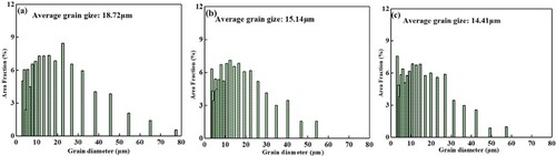
Figure 17. Inverse pole figure (IPF) maps of the columnar grain region in wire arc additive manufacturing of 18Ni-300 steel (a) NO-UIT-WAAM (b) I-UIT-WAAM (c) S-UIT-WAAM.
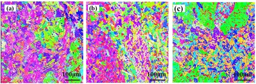
Figure 18. The KAM maps of the columnar grain region in wire arc additive manufacturing of 18Ni-300 steel (a) NO-UIT-WAAM (b) I-UIT-WAAM (c) S-UIT-WAAM.
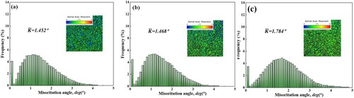
Figure 19. The orientation deviation angle maps of the columnar grain region in wire arc additive manufacturing of 18Ni-300 steel (a) NO-UIT-WAAM (b) I-UIT-WAAM (c) S-UIT-WAAM.
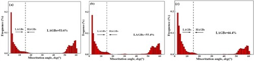
Figure 20. Pole figure of the columnar grain region in wire arc additive manufacturing of 18Ni-300 steel (a) NO-UIT-WAAM (b) I-UIT-WAAM (c) S-UIT-WAAM.
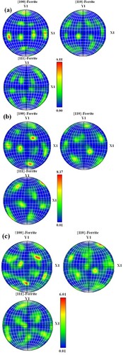
Comparing the orientation deviation angle maps shown in (a–c), the grain boundaries in the structure are classified as Low Angle Grain Boundaries (LAGBs) for angles <15° and as High Angle Grain Boundaries (HAGBs) for angles >15°. It is observed that the proportion of LAGBs in the NO-UIT-WAAM specimen is 53.6%, in the I-UIT-WAAM specimen is 55.4%, and in the S-UIT-WAAM specimen is 66.4%. As the dislocation density increases, the interference between dislocations impedes dislocation slip and plastic deformation, thereby increasing the material's strength and hardness. Contrasting the pole figures of the martensite matrix in the columnar grain region, it is observed that the texture orientation of the NO-UIT-WAAM specimen has a maximum density of 9.55, while that of the I-UIT-WAAM specimen has a maximum density of 8.37, and that of the S-UIT-WAAM specimen has a maximum density of 6.01, with the S-UIT-WAAM specimen having the lowest texture orientation. Therefore, it can be inferred that ultrasonic impact treatment primarily alters the microstructure in the columnar grain region, achieving grain optimisation in the columnar grain region by reducing the austenite content, lowering the texture in the columnar grain region, and enlarging the substructure in the columnar grain region.
3.2. The effect of ultrasonic impact on the element segregation of wire arc additive manufacturing microstructure
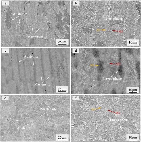
shows the SEM images of the martensitic aged steel fabricated by wire arc additive manufacturing. From (a,b), it can be observed that the microstructure of the sample NO-UIT-WAAM consists of martensite and austenite. The martensite phase is transformed from austenite, which originates from two parts: residual austenite phase in the rapidly solidified microstructure and austenite formed from the heating-induced transformation of unstable martensite phase during the repetitive heating process of the arc. (c,d) show the SEM images of the I-UIT-WAAM sample, which exhibits a microstructure similar to that of the sample NO- UIT-WAAM, with martensite and austenite phases. Austenite is mainly distributed at the boundaries of columnar grains, and Laves phase can be observed, primarily distributed within the austenite region. (e,f) display the SEM images of the S-UIT-WAAM sample, which also consists of austenite and martensite phases. However, its microstructure differs significantly from the previous two samples. The martensite phase exhibits a cellular or blocky distribution, and the Laves phase is sporadically distributed within the martensite phase. This is attributed to the change in grain growth direction caused by the effect of ultrasonic impact on the melt pool.
Figure 21. Sem images of wire arc additive manufacturing of 18Ni-300 steel.
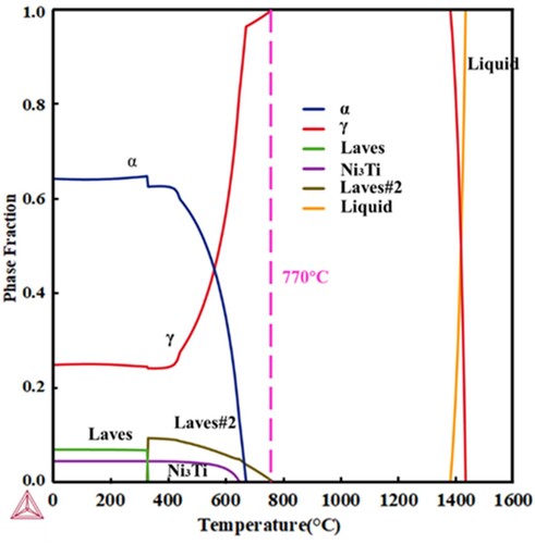
Thermo-Calc thermodynamic analysis software was used to analyze the composition changes of 18Ni-300 maraging steel at different temperatures. The composition was in a uniform state, representing the phase composition after uniform slow cooling. shows the phase diagram of 18Ni-300 maraging steel in equilibrium state [Citation30]. It can be observed that the liquid phase temperature of 18Ni-300 maraging steel is approximately 1400°C, and above 770°C, the phase composition is γ phase (fully austenitic phase), with the precipitated phases mostly dissolved into the matrix. At temperatures below 770°C, the Laves#2 phase appears, disappearing completely below 360°C. It has been reported that at 670°C, the α phase (martensitic phase) begins to appear, while the γ phase starts to decrease significantly. The Ni3Ti precipitated phase begins to appear at 630°C and can remain stable down to room temperature, while the Laves phase begins to appear at 360°C and can also remain stable at room temperature. Therefore, it can be inferred that 770°C is the temperature at which complete transformation to austenite occurs. The phases stable at room temperature include Ni3Ti precipitated phase, Laves phase, γ phase, and α phase. The Laves#2 phase is generally considered to be the Fe2Mo [Citation31,Citation32] precipitated phase, while the Laves phase is generally considered to be the precipitated phases such as Ni3Mo [Citation33]and NiAl [Citation34].
Figure 22. Solidification phase diagram of 18Ni-300 maraging steel in equilibrium state.
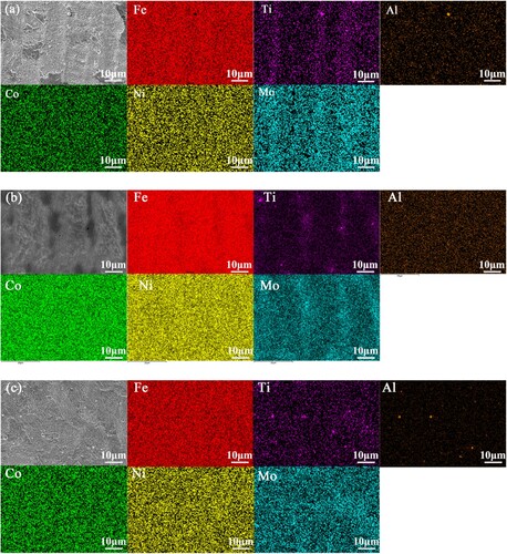
To investigate the effect of ultrasonic impact on element segregation in WAAM 18Ni-300 steel, EDS surface analysis was conducted on the specimens. It was found that in the NO-UIT-WAAM specimen, typical columnar grain microstructure formed due to grain solidification direction aligning with the heat flow direction, resulting in elemental distribution differences. As shown in , Ti and Mo formed a distinct segregation band, appearing at intergranular positions where Ti and Mo enrichment positions manifested as Fe depletion. The segregation of Ti and Mo is notably related to the differences in diffusion coefficients of alloy elements during rapid solidification. The solidification of the NO-UIT-WAAM specimen is characterised by non-equilibrium rapid solidification. With rapid solidification progressing, more alloy elements are enriched in the liquid metal, retained in the intergranular regions during the late stages of solidification to form enrichment, among which Ti and Mo segregation is most prominent. The surface scan of the I-UIT-WAAM specimen, as shown in (b), exhibited similar elemental segregation patterns to the NO-UIT-WAAM specimen, with Ti and Mo segregation appearing in band-like patterns, and the two almost coinciding. The microstructure of the I-UIT-WAAM specimen has already solidified, resulting in less influence of segregation on alloy element segregation. The surface scan of the S-UIT-WAAM specimen, as shown in (c), did not exhibit distinct Ti and Mo segregation bands in the elemental distribution map. The analysis revealed that under different ultrasonic application methods of I-UIT-WAAM and S-UIT-WAAM, the solute segregation in the microstructure significantly differed. In the case of S-UIT-WAAM, ultrasonic energy is transmitted through the deposition layer via high-frequency vibration, passing through the solid–liquid interface into the liquid metal. The presence of ultrasonic waves increases the nucleation rate of the liquid metal, creating more nucleation sites at the solid–liquid interface. Additionally, it can achieve grain refinement through grain fragmentation and refinement [Citation35], leading to a reduction in segregation located at intergranular positions.
Figure 23. EDS maps of wire arc additive manufacturing of 18Ni-300 steel.
To better reflect the solute segregation within and between grains, EDS point tests were conducted on the specimens, and the data obtained are shown in . It is observed that in the NO-UIT-WAAM specimen, the contents of Ni, Mo, and Ti in region A1 are 18.71%, 7.36%, and 1.32%, respectively, while in position M2, they are 17.15%, 4.37%, and 0.37%. Position A1 represents the interdendritic region, while position M2 represents the dendritic interior region. Significant solute segregation of Ni, Mo, and Ti elements is observed within and between dendrites, with Ni, Mo, and Ti showing the most significant segregation. For the I-UIT-WAAM specimen, the contents of Ni, Mo, and Ti in position A2 are 18.86%, 7.15%, and 1.38%, respectively, while in position M2, they are 17.23%, 4.13%, and 0.44%. The microstructure of the I-UIT-WAAM specimen exhibits elemental segregation patterns similar to those of the NO-UIT-WAAM specimen, mainly due to the similarity in their solidification processes. In the S-UIT-WAAM specimen, the contents of Ni, Mo, and Ti in position A3 are 18.20%, 6.60%, and 1.05%, respectively, while in position M3, they are 17.71%, 4.37%, and 0.47%. A comparison reveals that the ultrasonic impact treatment method applied to the S-UIT-WAAM specimen significantly affects the solute segregation of Ni, Mo, and Ti elements in the microstructure. The segregation of Ni, Mo, and Ti within and between grains is significantly reduced, resulting in a more uniform distribution of elements in the S-UIT-WAAM specimen.
Table 3. Elemental content analysis at different positions by EDS.
Using JMatpro 7.0 software to analyze the Ms of each region, the elemental distribution data from was utilised as data for different regions, resulting in . The Ms for position A1 of the NO-UIT-WAAM specimen is −106.0°C, for position A2 of the I-UIT-WAAM specimen is −98.8°C, and for position A3 of the S-UIT-WAAM specimen is −23.7°C. Therefore, upon cooling to room temperature, the Ms of the alloy element-enriched regions is not reached, and the microstructure exists in the form of residual austenite. For the NO-UIT-WAAM specimen, the Ms of position M2's microstructure is 160.5°C, while for the I-UIT-WAAM specimen, it is 171.1°C. For the S-UIT-WAAM specimen, the Ms of position M3's microstructure is 102.8°C. Upon decreasing the temperature to the Ms point, austenite transforms into martensite, which remains stable in the martensitic phase at room temperature. From the above analysis, it is evident that the stability of residual austenite at room temperature is related to the presence of stable elements (Ni, Mo, Ti) within the microstructure. These stable elements can lower the Ms to a temperature below the ambient temperature. Therefore, during the cooling process from high temperatures to room temperature, incomplete martensitic transformation of the microstructure occurs, leaving untransformed austenite phases within the structure. The application method of S-UIT-WAAM effectively suppresses the segregation of alloy elements in the microstructure during grain solidification. Hence, it can explain the lower austenite content observed in the S-UIT-WAAM specimen as mentioned earlier.
Table 4. Calculation of martensitic transformation temperature (Ms) using JMatpro 7.0 software.
3.3. Mechanical properties of the formed component
3.3.1. Hardness
The microhardness of wire arc additive manufactured 18Ni-300 steel is depicted in . The average hardness of the NO-UIT-WAAM specimen is 392.9 ± 41.9 HV. Analysing the hardness variations at different positions, it is evident that the hardness varies significantly between the top, middle, and bottom positions, with the highest average hardness observed at the bottom, followed by the middle position, and the lowest at the top position. The increase in hardness from top to bottom indicates that the incremental wire arc additive manufacturing has caused a transformation in the microstructure, driven by repetitive thermal cycles and accumulated heat, effectively promoting the effect of precipitation strengthening [Citation31]. Therefore, the single-layer multi-pass formed part exhibits significant hardness variations in different regions. The average hardness of the I-UIT-WAAM specimen is 402.6 ± 36.87 HV, while that of the S-UIT-WAAM specimen is 420.4 ± 47.8 HV, indicating that the S-UIT-WAAM specimen exhibits the highest average hardness. shows the average hardness variations at different positions. It can be observed that the average hardness of specimens subjected to ultrasonic impact treatment at different positions is consistently higher than that of the NO-UIT-WAAM specimen. This suggests that the strengthening effect induced by plastic deformation caused by ultrasonic impact treatment persists between the deposition layers.
Figure 24. Microhardness of 18Ni-300 steel in wire arc additive manufacturing with ultrasonic impact assistance.
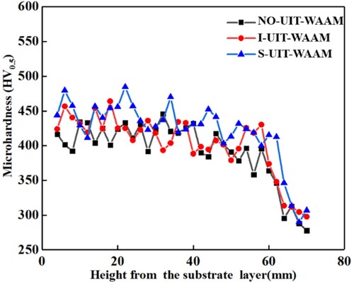
Table 5. Hardness variation at different positions.
3.3.2. Tensile properties
The mechanical properties of the components are shown in and . For the NO-UIT-WAAM specimen, the tensile strength in the horizontal direction is 1220.6 ± 36 MPa, and the horizontal direction yield strength is 1128.4 MPa,the tensile-to-yield ratio (the ratio of yield strength to tensile strength) is 0.92, while in the vertical direction, the tensile strength is 1171 ± 72.6 MPa, and the vertical direction yield strength is 1071.3 MPa, the tensile-to-yield ratio is 0.91. The elongation in the horizontal direction is 14.2 ± 1.3%, and in the vertical direction, it is 12.8 ± 3.1%. The I-UIT-WAAM specimen undergoes ultrasonic impact treatment applied solely to the deposition layers by subjecting them to high-frequency loads. Its tensile strength in the horizontal direction is 1309.6 ± 38.7 MPa, and the horizontal direction yield strength is 1193.5 MPa, the tensile-to-yield ratio is 0.91, the tensile strength in the vertical direction, it is 1278 ± 42.1 MPa, and the vertical direction yield strength is 1134.6 MPa, the tensile-to-yield ratio is 0.89. The elongation in the horizontal direction is 13.96 ± 0.85%, and in the vertical direction, it is 14 ± 0.7%. The S-UIT-WAAM specimen's tensile strength in the horizontal direction is 1401.3 ± 57.6 MPa, and the horizontal direction yield strength is 1261.9 MPa, the tensile-to-yield ratio is 0.90, while in the vertical direction, the tensile strength is 1327 ± 9.5 MPa, and the vertical direction yield strength is 1206.1 MPa, the tensile-to-yield ratio is 0.90. The elongation in the horizontal direction is 13.2 ± 2.24%, and in the vertical direction, it is 13.7 ± 0.61%. It is observed that the mechanical properties of specimens subjected to vertical tensile testing are consistently lower than those of horizontal specimens. This can be attributed to the microstructural differences at the interfaces, where the microstructure of WAAM's single-layer and multi-layer structure within the deposition layers and defects on the plane perpendicular to the vertical direction tend to form first. As a result, interfaces in vertically printed samples experience higher stress concentrations, providing easier paths for the nucleation and propagation of voids and microcracks. In horizontal specimens, lower stress concentrations at the interface hinder the opening, expansion, and coalescence of voids or cracks, delaying fracture and resulting in higher elongation. As mentioned earlier, UIT treatment suppresses the texture at interlayer interfaces, thereby reducing the differences in mechanical properties between the horizontal and vertical directions in I-UIT-WAAM specimens. Moreover, the ultrasonic impact effect significantly enhances the mechanical properties in the vertical direction. Additionally, different methods of applying ultrasonic impact result in varying performance enhancements. Compared to specimens without ultrasonic treatment, the tensile strength of horizontal and vertical directions in I-UIT-WAAM specimens increases by 7.3% and 9.1%, respectively, while in S-UIT-WAAM specimens, it increases by 14.6% and 11.3%, respectively, with no significant decrease in elongation compared to those without ultrasonic impact treatment. This is because ultrasonic impact treatment plays a crucial role in inducing plastic deformation within the deposition layers during interlayer deposition, with the method of S-UIT-WAAM showing a more pronounced effect on performance enhancement.
Figure 25. Mechanical properties of 18Ni-300 steel in wire arc additive manufacturing with ultrasonic impact assistance. (a) tensile strength and elongation (b) stress-strain curves.
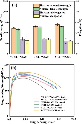
Table 6. Tensile strength and elongation of 18Ni-300 steel in wire arc additive manufacturing with ultrasonic impact assistance.
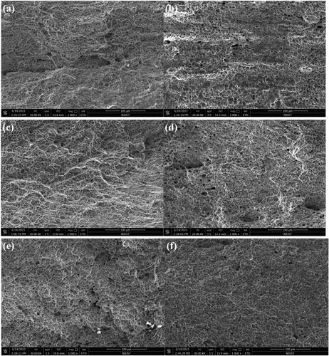
(a,b) depict the typical fracture morphology of the NO-UIT-WAAM specimen in the horizontal and vertical directions, respectively. It can be observed that the horizontal fracture surface of the NO-UIT-WAAM specimen exhibits prominent cleavage steps and dimples, while the vertical fracture surface shows cleavage planes with significantly fewer dimples compared to the horizontal fracture surface. Moreover, the number of dimples located at the steps is noticeably reduced. The appearance of cleavage steps along the low-refractive-index grain planes is a prominent feature of low-energy brittle fracture, indicating a brittle-ductile mixed fracture in both horizontal and vertical fractures of the NO-UIT-WAAM specimen. (c,d) illustrate the typical fracture morphology of the I-UIT-WAAM specimen in the horizontal and vertical directions, respectively. The horizontal fracture surface of the I-UIT-WAAM specimen exhibits numerous dimples but also shows abundant cleavage textures, presenting a river-like pattern, indicating a brittle-ductile mixed fracture as well. (e,f) show the typical fracture morphology of the S-UIT-WAAM specimen in the horizontal and vertical directions, respectively. It is noticeable that the horizontal fracture surface of the S-UIT-WAAM specimen presents more dimples compared to the vertical fracture surface, and the dimples are deeper. Additionally, distinct cleavage planes can be observed, indicating a ductile fracture characteristic.
Figure 26. Microscopic morphology of fracture surfaces in wire arc additive manufacturing of 18Ni-300 steel with ultrasonic impact assistance.
4. Conclusion
This study investigates the effects of different ultrasonic impact treatment methods on the microstructure and mechanical properties of 18Ni-300 maraging steel. The following conclusions are drawn:
At the top of the formed component, ultrasonic impact treatment significantly refines the grain size, with S-UIT-WAAM exhibiting the most effective grain refinement. The range of nanocrystalline zones formed is larger, with a nanocrystalline zone of approximately 230μm. Compared to NO-UIT-WAAM and I-UIT-WAAM specimens, the grain growth direction of S-UIT-WAAM specimens is altered, and plastic deformation is more easily induced within the grains, resulting in lower grain anisotropy in S-UIT-WAAM specimens.
In the central region of the formed component, the austenite content of S-UIT-WAAM specimens is significantly lower, at only 1.7%. Additionally, compared to the NO-UIT-WAAM specimen, the grain sizes of the I-UIT-WAAM and S-UIT-WAAM specimens are refined by 23.6% and 29.9%, respectively, with the lowest texture density observed in S-UIT-WAAM specimens.
EDS scanning results indicate that S-UIT-WAAM reduces the elemental segregation of Ni, Ti, and Mo within and between grains, resulting in a significant decrease in austenite content.
The average hardness of S-UIT-WAAM specimens at different locations is the highest. Compared to the specimens without ultrasonic treatment, the tensile strength of the I-UIT-WAAM specimens in the horizontal and vertical directions is increased by 7.3% and 9.1%, respectively. The tensile strength of the S-UIT-WAAM specimens in the horizontal and vertical directions is increased by 14.6% and 11.3%, respectively.
Disclosure statement
No potential conflict of interest was reported by the author(s).
Data availability statement
The data that support the findings of this study are available from the corresponding author upon reasonable request.
Additional information
Funding
References
- Rodrigues TA, Duarte V, Miranda RM, et al. Current status and perspectives on wire arc additive manufacturing (WAAM). Materials (Basel). 2019;12(7):1121. doi: 10.3390/ma12071121
- Paul AR, Mukherjee M. Metal alloys and beyond: analysing the horizon of WAAM Materials[M]//Wire arc additive manufacturing. Boca Raton: CRC Press; 2024. p. 89–138.
- Jafari D, Vaneker THJ, Gibson I. Wire arc additive manufacturing: opportunities and challenges to control the quality and accuracy of manufactured parts. Mater Des. 2021;202:109471.
- Song SS, Chen J, Ye J, et al. Test and analysis of the interfacial bond behaviour of circular concrete-filled wire-arc additively manufactured steel tubes. J Buil Eng. 2024;82:108171.
- Floreen S. The physical metallurgy of maraging steels. Metall Rev. 1968;13(1):115–128.
- Malakondaiah G, Srinivas M, Rao PR. Ultrahigh-strength low-alloy steels with enhanced fracture toughness. Prog Mater Sci. 1997;42(1):209–242.
- Stein F, Palm M, Sauthoff G. Structure and stability of laves phases. Part I. Critical assessment of factors controlling Laves phase stability. Intermetallics. 2004;12(7-9):713–720.
- Eumann M, Sauthoff G, Palm M. Phase equilibria in the Fe–Al–Mo system–part I: stability of the laves phase Fe2Mo and isothermal section at 800 C. Intermetallics. 2008;16(5):706–716. doi: 10.1016/j.intermet.2008.02.006
- Jose B, Manoharan M, Natarajan A, et al. Current research and developments in welding of 18% nickel maraging steel. Proc Inst Mech Eng Pt J. Mater Des Appl. 2023;237(6):1295–1318.
- Li K, Yang T, Gong N, et al. Additive manufacturing of ultra-high strength steels: a review. J Alloys Compd. 2023;965:171390.
- Moshka O, Brosh E, Ezersky V, et al. Addressing the issue of precipitates in maraging steels – unambiguous answer. Mater Sci Eng A. 2015;638:232–239. doi: 10.1016/j.msea.2015.04.067
- Li J, Zhan D, Jiang Z, et al. Progress on improving strength-toughness of ultra-high strength martensitic steels for aerospace applications: a review. J Mater Res Technol. 2023;23:172–190.
- Schiavo CP, Zucarelli TA, Reis DAP. Maraging 300 steel plasma welding characterization for aerospace application. Mater Res. 2023;26:e20220532.
- Xu X, Ganguly S, Ding J, et al. Microstructural evolution and mechanical properties of maraging steel produced by wire+ arc additive manufacture process. Mater Charact. 2018;143:152–162. doi: 10.1016/j.matchar.2017.12.002
- Peng D, Ang ASM, Michelson A, et al. Analysis of the effect of machining of the surfaces of WAAM 18Ni 250 maraging steel specimens on their durability. Materials (Basel). 2022;15(24):8890. doi: 10.3390/ma15248890
- Zhang J, Fan J, Xu J, et al. The effect of heat input on the microstructure and mechanical properties of 18Ni 300 maraging steel fabricated by arc directed energy deposition. Mater Sci Eng A. 2023;884:145545.
- Xu X, Ganguly S, Ding J, et al. Improving mechanical properties of wire plus arc additively manufactured maraging steel through plastic deformation enhanced aging response. Mater Sci Eng A. 2019;747:111–118. doi: 10.1016/j.msea.2018.12.114
- Wang C, Li Y, Tian W, et al. Influence of ultrasonic impact treatment and working current on microstructure and mechanical properties of 2219 aluminium alloy wire arc additive manufacturing parts. J Mater Res Technol. 2022;21:781–797. doi: 10.1016/j.jmrt.2022.09.055
- Diao M, Guo C, Sun Q, et al. Improving mechanical properties of austenitic stainless steel by the grain refinement in wire arc additive manufacturing assisted with ultrasonic impact treatment. Mater Sci Eng A. 2022;857:144044.
- Gou J, Wang Z, Hu S, et al. Effects of ultrasonic peening treatment in three directions on grain refinement and anisotropy of cold metal transfer additive manufactured Ti-6Al-4V thin wall structure. J Manuf Process. 2020;54:148–157. doi: 10.1016/j.jmapro.2020.03.010
- Chen Y, Zhang X, Ding D, et al. Integration of interlayer surface enhancement technologies into metal additive manufacturing: a review. J Mater Sci Technol. 2023;165:94–122.
- Wang J, Xue Y, Xu D, et al. Effects of layer-by-layer ultrasonic impact treatment on microstructure and mechanical properties of 304 stainless steel manufactured by directed energy deposition. Addit Manuf. 2023;68:103523.
- Zhou C, Jiang F, Xu D, et al. A calculation model to predict the impact stress field and depth of plastic deformation zone of additive manufactured parts in the process of ultrasonic impact treatment. J Mater Process Technol. 2020;280:116599.
- Guo Y, Xu X, Chen Z, et al. Deformation mechanisms and surface/interface characteristics of titanium-based thermoplastic FMLs under ultrasonic impact loading. Ultrasonics. 2024;138:107217.
- Sohn SS, Song H, Suh B-C, et al. Novel ultra-high-strength (ferrite + austenite) duplex lightweight steels achieved by fine dislocation substructures (taylor lattices), grain refinement, and partial recrystallization. Acta Mater. 2015;96:301–310. doi: 10.1016/j.actamat.2015.06.024
- Chen Y, Xu M, Zhang T, et al. Grain refinement and mechanical properties improvement of inconel 625 alloy fabricated by ultrasonic-assisted wire and arc additive manufacturing. J Alloys Compd. 2022;910:164957.
- Karthik GM, Kim ES, Sathiyamoorthi P, et al. Delayed deformation-induced martensite transformation and enhanced cryogenic tensile properties in laser additive manufactured 316L austenitic stainless steel. Addit Manuf. 2021;47:102314.
- Kubin LP, Mortensen A. Geometrically necessary dislocations and strain-gradient plasticity: a few critical issues. Scr Mater. 2003;48(2):119–125. doi: 10.1016/S1359-6462(02)00335-4
- Sun L, Huang L, Wu P, et al. Progress on the effect and mechanism of ultrasonic impact treatment on additive manufactured metal fabrications. Crystals (Basel). 2023;13(7):995. doi: 10.3390/cryst13070995
- Ooi SW, Hill P, Rawson M, et al. Effect of retained austenite and high temperature laves phase on the work hardening of an experimental maraging steel. Mater Sci Eng A. 2013;564:485–492. doi: 10.1016/j.msea.2012.12.016
- Xu Y, Mishra B, Narra S P. Experimental investigation of in-situ microstructural transformations in wire arc additively manufactured maraging 250-grade steel. Mater Charact. 2022;190:112065.
- Guo L, Zhang L, Andersson J, et al. Solidification structures and phases in wire arc additive manufactured C250 maraging steel. Mater Sci Technol. 2022;39(5):582–590. doi: 10.1080/02670836.2022.2128577
- Tekin T, Ischia G, Naclerio F, et al. Effect of a direct aging heat treatment on the microstructure and the tensile properties of a 18Ni-300 maraging steel produced by laser powder Bed fusion. Mater Sci Eng A. 2023;872:144921.
- Sun L, Simm TH, Martin TL, et al. A novel ultra-high strength maraging steel with balanced ductility and creep resistance achieved by nanoscale β-NiAl and laves phase precipitates. Acta Mater. 2018;149:285–301. doi: 10.1016/j.actamat.2018.02.044
- Lv J, Alexandrov IV, Luo K, et al. Microstructural evolution and anisotropic regulation in tensile property of cold metal transfer additive manufactured Ti6Al4 V alloys via ultrasonic impact treatment. Mater Sci Eng A. 2022;859:144177.