
 ?Mathematical formulae have been encoded as MathML and are displayed in this HTML version using MathJax in order to improve their display. Uncheck the box to turn MathJax off. This feature requires Javascript. Click on a formula to zoom.
ABSTRACT
In selective laser melting technology, the productivity and the efficiency of powder utilisation were examined. Individual components of the printing time were determined by developing a specially designed model. Two main components of the powder recoating and the laser exposure time were given as a function of the filling ratio of the cross-section. Based on the results, the spreading time can increase the printing time by several hours, depending on the filling factor of the cross-section. In the case of a sampling of 70 prints, the individual elements and process of the powder usage were determined, as well as the mass measurement of the different amounts of powder in the case of 316L and Ti6Al4V materials. It turned out that 45–80% of the powder amount is not used to build the model, which is an essential for both printer users and equipment developers for material cost prediction.
1. Introduction
Like all new technologies, additive manufacturing also underwent the process described by Gartner's hype curve [Citation1]. Accordingly, when the specifics of the technology are revealed compared to the initial expectations, this procedure also finds its place alongside the traditional procedures. At the same time, additive manufacturing can have advantages not only from the point of view of production technology but also because the technological limitations of production are smaller, and geometries that are not able or difficult with traditional processes can be produced. Among the metal printing processes, one of the most common technologies is the selective laser melting (SLM) or laser powder bed fusion (L-PBF) process [Citation2]. In addition, there are other processes such as DED (Direct Energy Deposition) [Citation3], metal fused filament fabrication [Citation4], metal binder jetting [Citation5], and electron beam melting [Citation6]. The fields of application can be diverse, but mainly the aviation industry [Citation7], medical industry [Citation8], and automotive industry [Citation9] are the primary users.
The most common metal materials used in the SLM process are 316L steel, Ti6Al4V alloy, AlSi10Mg [Citation10] or special aluminium alloys [Citation11] and some special tungsten alloys [Citation12]. The printing of copper-based alloys has already begun, which is a unique challenge for this process due to the high reflection of the laser beam [Citation13]. In addition, there are already solutions where different types of materials are combined in the same workspace with multi-material solutions [Citation14], taking advantage of both materials.
In the case of additive manufacturing processes, productivity is one of the challenges that awaits a solution and constantly motivates technology and equipment developers. Consequently, increasing productivity is one of the continuous objectives [Citation15]. Another challenge is improving the efficiency of powder use, which is a goal due to the high powder cost [Citation16].
1.1. Productivity of SLM process
Selective laser melting is suitable for printing highly complex pieces, with the fact that the time required for printing is typically one of the longest due to the thin printing layer thickness. Of course, this depends on several things, such as the size, orientation, number of models to be printed, and the thickness of the applied printing layer [Citation17]. Some developments aim to increase productivity by increasing the layer thickness [Citation18]. If appropriate, for example, instead of a layer thickness of 30 µm, the given model can be created with fewer layers, provided that the part can still meet the requirements despite the reduction in geometrical resolution. From the technology side, the laser scanning strategy [Citation19] also affects the structure [Citation20] and internal structure [Citation21] of the printed material. In addition, the effect of the laser power and speed parameters has already been relatively well explored [Citation22]. The time-consuming SLM process can be divided into three main parts. These are the preparatory operations for printing (orientation, supporting, slicing, printing simulation, technology assignment), the 3D printing itself (layer-by-layer creation) and the necessary post-operations (material structure modification, geometry modification and surface treatments). The input and output parameters determining fertility are already known [Citation23].
The time of the printing operation can be divided into equipment preparation (powder loading and handling, heating), the printing time where the component is built layer by layer, and the finishing operations (unboxing, cleaning, sieving) [Citation24]. In many cases, only the print time is given for a particular part, but all other operation times also significantly affect the overall lead time. There are processes where significant operating times also result from heating the powder bed [Citation25] even before printing. After the building is finished, there is also a cooling phase, which can sometimes last for long hours. There are already hybrid solutions to reduce individual operation times when SLM printing and geometrical post-processing (machining) are done within the same equipment. The traditional subtractive and additive methods are used together [Citation26]. These solutions increase the geometric accuracy of the printed model and improve their surface quality after it leaves the equipment so that post-processing related to cutting can be replaced afterwards.
In general, however, depending on the size of the model and its placement in the printing workspace [Citation27], the printing time from the layer is the longest. Accordingly, one of the most effective ways to increase productivity is to reduce the main machine time of building from layer to layer. During the layer-by-layer building, powder spreading (recoating) and selective laser exposure are repeated as two main operations, one after the other. Developments in this direction have already been made to further the spread of technology. One way to do this is, for example, that with laser powder bed technology, several laser beams work simultaneously in a larger workspace [Citation28], which can reduce lasering time. With the help of the scanner optics that move the laser beam, the laser movements already take place at a high speed, so only the increase of this is no longer worthwhile. In addition, the high movement speed can be used during the transition between individual laser irradiations because the maximum speed for the technology is limited depending on the available laser power to create the desired elemental seams and the desired density of the part. It is made possible by the ever-increasing laser power built into printing equipment [Citation29]. Furthermore, to further increase the productivity of the process, a development direction is to increase the layer thickness, which contributes to the installation and use of higher-power lasers. But, it is important that the model can reach the desired density of 99% or more [Citation30].
Another printing operation is the recoating process, for which several solutions exist by coordinating the characteristics of powder and powdering systems [Citation31]. Some devices feed powder from a powder container and move it upwards into the building plane and the spreading unit moves it to the building chamber. There are solutions in which the required amount of powder is delivered to the work plane from a container or dispenser placed above the recoating pane and the recoater moves it to the work chamber. In both cases, however, the powder recoater is usually designed as a roller or blade moved by a CNC axis [Citation32], whose speed, based on the parameters of the powder spreader [Citation33], is decisive during printing.
As a result, the time of powder spreading, and laser exposure determines the time of layer-by-layer printing. However, the times for these two main operations can vary greatly depending on how filled the cross-section to be printed is compared to the entire cross-section. The motivation behind this research stemmed from that fact there is a gap in scientific knowledge in this matter because there are few specific measurement data in the literature regarding the relation and ratios of powder spreading and laser irradiation times, mainly depending on the exposure ratio of the printable cross-section. As a result, one of the goals of this investigation was to develop a methodology for a specific device, with the help of which these conditions can be explored and evaluated.
1.2. Powder utilisation of SLM process
One of the advantages of the additive manufacturing process is that, during production, layer by layer, only the materials necessary for the printing of the model and the supports are used. Don't have to deal with the scrap or material loss typical of traditional processes. The amount of material loss varies with different metal printing processes, but specific data are rarely provided.
In the powder bed technique, the selectivity of selective laser melting also means that the material is fused along the paths travelled by the laser beam by creating a molten pool. Then, after solidification, an elementary seam is formed. The printed model is built from the totality of these seams. The powder particles that the laser beam has not melted are ideally placed in one or more powder collection containers, from which, after sieving, the particles that have stuck together can be filtered by the sieving process. After that, the remaining powder can be used again. To continuously ensure the constant quality of the powder, the powder that has already been used once is mixed with the original powder in each proportion. There are different strategies for the reuse of powder [Citation34], and the main factors influencing this have been determined [Citation35]. If the investigation of the effect of completely original powder and used powder [Citation36] on the quality of printed parts has already been investigated by several researchers for various materials, 316L [Citation37], Ti6Al4V [Citation38], AlSi10Mg [Citation39]. The powder can be managed manually or partially automated, but a certain amount of powder loss must be expected during the technology.
The selective laser melting technology can be compared to laser micro-welding, where a molten pool is created from the powder and solid parts of the previously solidified model. Accordingly, the basic phenomena of welding technology can be observed here. The SLM process is characterised by the fact that during the laser exposure (irradiation) of the spread powder, material transport phenomena emerge, like the spattering and evaporation phenomenon common in welding processes [Citation40]. In many cases, it is determined by analysing video recordings of the process [Citation41], which are also recorded with special fast camera recordings [Citation42], with an in-situ process monitoring system [Citation43], and with X-rays [Citation44]. In addition, with the help of flow measuring sensors placed in the working area of the equipment, data is collected about the flow conditions for a given gas inlet and outlet design [Citation45]. The basic phenomena related to material transport that take place in the vicinity of the laser-melted melt pool were determined [Citation46]. These include, for example, metal vaporisation, spattering, and the characterisation of the related process [Citation47], the appearance of various condensates [Citation48], the formation of plasma, the ejection of powder particles [Citation49] or even the spatter ejection profiles from melt pool [Citation50].
If parts of the material leaving the melt pool fall back into the powder bed, this particle can negatively affect the quality of the laser exposure and powder spreading. Therefore, during the printing operation, a specific direction and amount of shielding gas is flowed and circulated above the powder layer, which minimises the negative effects of material transport. Some researchers investigated the impact of the protective gas suction system on the quality of the part to be printed and showed that by increasing the gas speed, the main mechanical properties of the model also improve [Citation51], and the flow speed also influences the powder loss [Citation52]. The uniformity of the shielding gas flow is also important in terms of the density and mechanical properties of the printed model [Citation53]. As a result of these investigations, they also deal with the further development of various elements of the shielding gas circulation system [Citation54], and the developments take place. For example, other gases, even helium, are added to the argon gas to achieve less spattering [Citation55]. By using the experimental knowledge gained about it, it is also possible to analyse these processes with the help of simulation software [Citation56,Citation57], in which different flow simulation methods are used even for different metals [Citation58].
Among the researchers, some studies deal with the efficiency of powder utilisation and determine the main elements that can be interpreted as powder loss [Citation59]. Here, the researchers are already suggesting that the powder's efficiency can be significant. One element of the protective gas circulation system is the filters used in one or more steps, which filter the powder transported from the work chamber. The powder particles in the exhausted shielding gas will no longer be used in the future but will be disposed of together with the replacement of the filter. It also means that not only the spattered and problematic particles are removed from the workspace, but also powder particles that would otherwise have been suitable for building. One might think that a relatively small amount of powder enters the filter system, but the extent of this needs to be clarified. Since the printing operation often lasts for many hours and this protective gas stream must be continuously maintained, this phenomenon occurs during the entire printing time.
Little information about this phenomenon and specific data are available in the literature. Our own experience is that the amount of powder that enters the filter due to the protective gas flow is not negligible. So, knowing how much powder is used to make a particular model is essential. Therefore, an examination of this was carried out. That is why one part of our tests focused on how and in what proportion the powder loaded into the printing equipment is used for the printed model and what amount of loss should be expected not only in the case of one component but in a larger number of printed jobs. It also determines the amount of material used and the cost of production, which is higher than in the case of traditional manufacturing methods.
2. Experiments
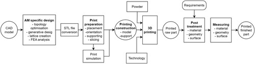
The applied process related to selective laser melting technology can be seen in , starting from the CAD model to the real part that meets the requirements. Accordingly, the main steps are creating the additive specific design, which means topology optimisation, generative design, and the creation of spatial lattice structures and their finite element analysis. After STL (Standard Triangle Language) file conversion the next step is preparation for printing, which includes positioning, orientation, supporting, and slicing the part in the building platform. If necessary, a print simulation step is performed before printing. It consists of the model and the support. In addition to the printing design, the several-hour printing process begins by entering the raw powder material and technological parameter set. At the end of the printing, we have a raw part, which goes through post-processing operations depending on the requirements. Post-processing can also be applied to material structure, geometry, and surface quality. Also, the post-processing results are measured and validated for the same characteristics depending on the requirements. A finished 3D part that meets the requirements is produced at the end of the process.
Figure 1. The applied process flow of SLM printing of metals.
During our investigations, we dealt with certain parts of this basic process. The central element of the process is the metal printing equipment. During our tests, we used an SLM device that is suitable for accurately measuring the mass of the used powder quantity due to its small size and manual operating characteristics. The printer used was an EOS M100 device with a cylindrical workspace. The models are built on a 15 mm high and 100 mm diameter building platform. The height of the workspace is 100 mm.
It is also possible to print several types of materials from the equipment. Printed parts were made of steel (316L) and titanium (Ti6Al4V). The powder used was commercially available EOS 316L (EOS StainlessSteel 316L 9011-0032) and EOS Ti6Al4V (EOS Titanium Ti64 9011-0039). The composition of the metals is shown in and .
Table 1. The composition of the applied 316L powder materials.
Table 2. The composition of the applied Ti6Al4V powder materials.
The thickness of the built layer was 20 µm, and we used default technological parameter sets of the equipment, which were not changed during our tests. The 316L_020_FlexM100_201 parameter set was used for the steel material, and the Ti64_020_FlexM100_100 parameter set for the titanium material. During the process, 4.6 purity argon gas was used as shielding gas. shows the main properties of the printed model and the powder used.
Table 3. Main properties of the applied materials.
2.1. Methodology for the printing time analysis
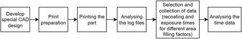
The main steps of our tests related to the analysis of the printing time are shown in . As a first step, a CAD design was developed that was suitable for evaluating the various cross-section filling ratios in one model. After printing, the time information was obtained by analysing the log files stored in the device. When analysing the time data, we split the laser irradiation and spreading times separately, and these were represented in the results.
Figure 2. The applied process flow for printing time analysis.
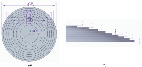
When designing the model, it was also important to obtain relevant information about the process using the minimum amount of material. Accordingly, a stepped design geometry was developed, and the model was placed on the building platform without support. The main characteristics can be seen in . The basic goal was to have time data available for the entire usable cross-section of the work chamber. The filling cross-section factors were between 10% and 90%. To prevent the printing time from being too long, steps were designed 1 mm high, in which 50 layers with the same parameters were completed. In the results, the time data of these 50 layers are illustrated.
Table 4. The main parameters of the printing time analysis.
The designed model is shown in . in two views. This geometry is suitable for contiguous cross-sections to provide time data. Stripe-type filling was used to infill the cross-section, which was done with a stripe width of 5 mm for each layer.
Figure 3. The developed model design for cross-section investigation, (a) upper view, (b) side view of the steps.
2.2. Methodology for powder utilisation
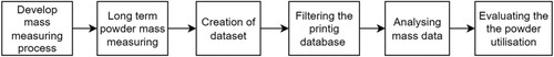
The main steps of the powder utilisation analysis can be seen in . The process began with the development of measurement studies, which meant a series of mass measurements over a more extended period. A digital scale with an accuracy of one gram was used for mass measurement. The masses were measured in different powder handling steps and at different equipment elements, such as the printing platform and the various containers used to store the powder (powder supply bin, powder collector bin). The data sets generated during the printing were filtered and analysed. Thus, those printing cases that proceeded without problems were included in the study (for example, the process did not have to be stopped, or there were no collisions or powder refills were realised).
Figure 4. The applied process flow for the powder utilisation analysis.
During the test, prints were made with steel and titanium, comprising 70 print jobs. . shows the main printing parameters for the two materials. Since the equipment has a small working space, the printing times ranged between 3 and 20 hours.
Table 5. The main parameters of the powder utilisation analysis.
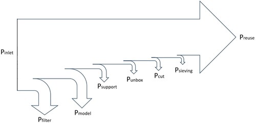
During the mass measurement, the goal was to follow the path of the powder fed into the equipment and, as a result, to reveal the utilisation efficiency of the powder. . shows the various elements of powder consumption in the Sankey diagram, from the powder inlet to the amount of sieved and reusable powder.
Figure 5. The Sankey diagram of powder utilisation in the case of the SLM process.
In the case of the applied metal printing equipment, the powder supply container is located above the building plane. From this container, a dosing unit is performed the dosing of the powder in front of the recoater blade. The recoater blade delivers the powder into the printing chamber and empties the excess into the collecting containers. The powder measuring tests could be carried out because the small workspace and the manual handling of small amounts of powder resulted in negligible losses. Therefore, the obtained mass measurement results provide information about the powder's actual use. We measured separately the mass of each container, the mass of the printing platform and the support and model on it, which even included the amount of powder between the support lattice.
The shielding gas circulation was switched on during the procedure to remove the spattered particles produced during laser melting. This airflow also removes and carries particles from the powder on top of the powder bed. The parameters used during the mass measurement and their interpretation are shown in . A sieve with a grid size of 63 µm was used during sieving.
Table 6. The interpretation of parameters in the case of the mass measurement.
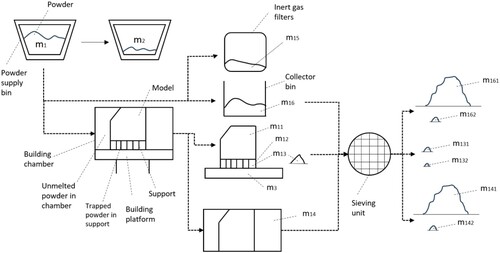
shows the path of the loaded powder in the metal printing equipment, the individual system components, their names, and the interpretation of the markings used. Accordingly, the amount of powder introduced for printing can be determined by the difference in the mass measured at the start and end of the upper powder supply bin (min). In contrast, the reusable powder is possible to get back from the process (mreuse) The difference between the two values was applied to the printing of the model and the printing of the support and lost during the process. Overall, the losses are made up of the amount of powder that entered the inert gas filter system during the several hours of layer-by-layer printing, the loss during the unfolding at the end of printing, the loss of powder during the separation of the workpiece and the support, and the loss of powder during sieving.
Figure 6. The visualisation of mass measurement parameters.
During the applied methodology, the formulas for the interpretation of powder utilisation were determined as follows. Here, we can interpret two different efficiencies, where one shows the powder usage efficiency directly only for the mass of powder used for building the model, and the other shows the powder usage efficiency related to the mass of the melted and solidified materials (model and support). The powder usage efficiency for the model is the primary one. Still, the combination of the model and the support can also be important since, in many cases, the support is a necessary part of the technology and is an unavoidable solution for successful printing. The powder utilisation efficiency is determined as follows:
During printing, the powder entering the printing equipment was determined based on the following formula:
The mass of powder that can be reused after sieving the powder coming out of the printer can be determined using the following formula:
The mass of powder loss during printing (mloss) can be calculated using the following formulas, which can be determined on the one hand as the sum of the individual loss elements. Still, since these are difficult to measure directly, it can also be determined by the difference between the mass of powder introduced into the printing process (min) and that which can be reused at the end of printing (mresue) and that can be used for printing the model (m11):
shows the distribution of the 70 print jobs and the total volumes associated with them on the diagram. Steel and titanium parts are marked with different colours. It illustrates that a wide volume range was examined for both raw materials.
Figure 7. The printed volumes of the 70 jobs in the case of the 316L and Ti6Al4V materials.
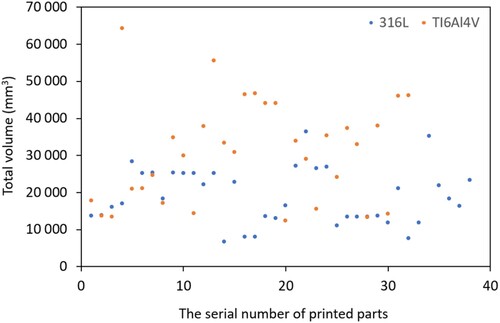
The following will present the test results of these printing cases. This long-term study provides a more complete picture of powder utilisation efficiency thanks to the large number of prints included in the study.
3. Results and discussion
The results of the analysis of printing time and powder consumption are presented in the following subsections.
3.1. Results of printing time analysis
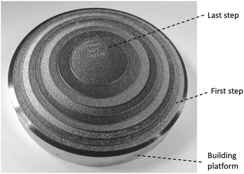
A picture of the model developed for the analysis of print times after it has been removed from the printer can be seen in . The step-by-step design can be seen in the recording. The part was built adequately during printing; however, as we expected, due to the large continuous and horizontally located cross-sections, internal stresses developed to a degree that slightly deformed the printing platform. Since the printed part was no longer needed, this deformation caused by the printing stress did not cause a problem. Only the time data required for its production was used from the log file generated in the equipment monitoring system. In addition, it was a helpful experience that, even in the case of such a model, significant internal stresses are created in the components. Thus, it was a good decision to shape the test body without support. If we had also used support, the printing of the part would have failed, even in the case of the first step. It confirms the importance of the aspects considered when developing the model.
Figure 8. The printed model for the time analysis.
The actual production data were recorded in the equipment log files during printing. Here, the laser irradiation times and powder spreading times were recorded separately in thousandths of a second resolution. Since a step on the model was 1 mm high in the Z direction, data was available for 50 layers. By averaging these data within a layer and indicating the standard deviation. It can be observed that the data is in a time range between 11 and 15 s. Within this, depending on the filling level of the cross-section, a slight increase can be observed as a trend, which can be explained by the fact that the spreading starts with powder dosing, where, as determined by the automatic system of the equipment, this varies to a different extent in the case of smaller and larger cross-section filling. Based on the measurement data, it was observed that there could be a difference of up to 20% in the spreading time at 10% and 40% in cross-sectional filling, which means 2.68 s per layer. For a 100 mm high part, porting causes an increase of 3.72 hours in the printing time.
In addition to the spreading time, the laser irradiation time is also significant. The laser irradiation time, in addition to applying a specific technology, depends on the filling of the cross-section. Accordingly, the larger the cross-section, the longer it takes to fuse the given layer. Thus, as the cross-section is filled, the laser exposure time increases proportionally. The combined representation of these two main time components can be seen in .
Figure 9. The recoating and laser exposure time data as a function of the cross-section filling ratios, in the case of Ti6Al4V.
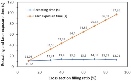
It can be observed from the diagram that the curves continuously separate from the cross-section filling of around 10%. The points displaying the laser irradiation time can be aligned in a straight line. The curve visualising spreading time depends only to a lesser extent on the filling of the cross-section, but the change is still close to 25–28%. The nature of the curve is less steep than the laser exposure time, which also means that the larger the cross-section, the more significant the laser exposure time is in the preparation time of the layers. The intersection of the two curves is formed where the time required due to the speed of the recoating system is the same as the time of laser exposure. Although this may vary depending on the equipment, it can be generally stated that if the exposure time is known and cross-sections created with shorter irradiation times are produced, the exposure time plays a significant role in the printing time. In such printing cases, speeding up the recoating and reducing the powder spread time can be a crucial step forward. The recoating time plays a minor role if the filled cross-section is large. During printing, we strive to saturate the printing platform as much as possible, so reducing the spreading time is a less important task if this can be achieved.
The smaller printing workspace means a recoating time. It is also motivating to make the smaller parts in smaller printing equipment if possible. If the recoating process is accelerated, the curve used for display is shifted downwards in parallel.
If we were to increase the speed of the laser movement, then, for example, the straight line describing the laser exposure time would shift downwards. This knowledge is a valuable methodology and input information for equipment manufacturers, users, and technology developers to improve production productivity. Because the competitiveness of technology can be significantly enhanced by faster printing. Of course, this is only a part of the total lead time, and in many cases, reducing the time required for the entire process can be achieved not only by reducing printing times.
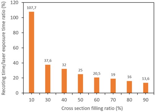
The ratio of recoating and laser exposure time is shown in , on which the significance of the spreading time decreases with the increase of the cross-section filling. Based on this, as the filling ratio of the cross-section increases from 30% filling, the laser irradiation time mainly determines the layer printing duration.
Figure 10. Ratio of the average recoating and laser exposure time as a function of cross-section filling ratio, in the case of Ti6Al4V.
In the case of the model developed during this study, the different layers were uniformly produced as a continuous cross-section. If the same filling is produced as several cross-sections, the rapid positioning movement of the laser beam between additional cross-sections is also added to this. Considering that the optical movement of the scanner can reach a speed of up to 7 m/s, the laser irradiation time remains decisive.
Based on the tests carried out with the presented methodology, specific time data can be obtained regarding how the recoating time and lasering time change with the filling ratio of the cross-section. Since one of the challenges of additive manufacturing is reducing print times, it provides beneficial input data for developments related to reducing print times. Based on the obtained data, it can be determined that, depending on the filling of the cross-section, the reduction of the powder spreading time, or the reduction of the laser irradiation time makes it possible to shorten the total printing time. In the case of smaller filling cross-sections, since recoating time is also significant, it should be reduced. In the case of larger filling cross-sections, however, the laser irradiation time dominates, so it is advisable to deal with its reduction. It is no coincidence that several laser beams are used simultaneously in a workspace to reduce the laser irradiation time, as seen in the literature.
3.2. Powder utilisation efficiency
In addition to the productivity issues discussed above, another essential feature of printing technology is a better and deeper understanding of powder consumption and its effectiveness. In addition to characterising the quality of the printed parts, both factors contribute to the costs. The final decision regarding the printability of a specific part is the result of economic analyses. That is why having a deeper understanding of powder use is essential. A general idea about additive manufacturing, as we have seen in the literature, is that we only add material where it is needed from the model's point of view. In addition, only a minimal amount of scrap is produced. However, our experience analysing many printing cases showed that powder use is more significant than the amount of valuable powder used for the model. It was the subject of our investigations, the results of which are presented below.
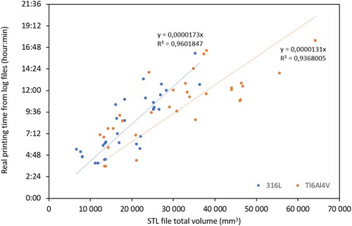
As a preliminary analysis, shows the relationship between the total printing time of real productions and the total volume of the model and the support in the case of the two material types (316L, Ti6Al4V). The regression lines fitted to the sets of points show a minor difference for the two raw materials. In terms of interpretations, this means that printing the same total volume in the case of steel takes longer to print. It may also result from the fact that different default technological parameter sets are set on the equipment for the two raw materials. So, in the case of steel, laser melting takes place at lower speeds, and because of this, the melting process of the layer takes longer, and as a result, the printing time is also longer.
Figure 11. The real printing time as a function of the total volume of support and model.
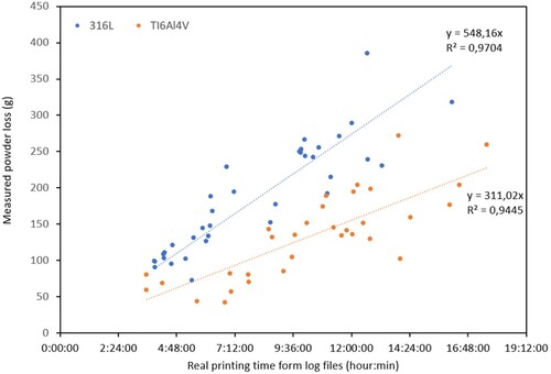
shows the powder mass loss data for 70 prints as a function of the total real production time. It can be seen in the diagram that the regression lines fitted to the sets of points for the two raw materials are separated from each other. In the case of the titanium alloy, however, less powder mass loss should be expected in addition to the production periods. If we also consider the differences in the density of the two raw materials, then calculating the slope of the regression lines appearing here yields a similar value. As a result, almost the same volume disappears for both materials. The difference in mass results from the difference in density.
Figure 12. The loss of powder as a function of the total printing time of the SLM printed part in the case of 316L and Ti6Al4V materials.
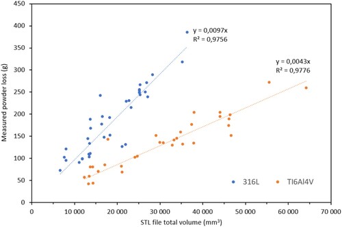
Since the volume of the model is given for the printing task, which is necessary for the implementation of the functions, we, therefore, examined the degree of powder loss in the case of the production of a given total volume for these two types of raw materials. shows the powder loss values that can be measured for individual prints as a function of the model's total volume and support volume. From the data in the diagram, it can be observed that the amount of powder loss changes almost linearly with the total volume. However, the slopes of the two regression lines are also different here. As we can see from the analysis by other researchers in the literature summary, this powder loss also arises from material transport phenomena created during printing, such as spattering. In the case of the two material types tested, the powder losses are higher than in the case of the 316L steel type in the case of the same total volume. When printing steel, you can count on approximately 2.26 times as much powder mass loss as when printing titanium alloy. This difference is higher than what would result from the density ratios, so the specific loss of steel powder for printing volume is higher than in the case of titanium alloy. Considering that the purchase price of titanium powder is more than three times higher concerning mass, it is essential to consider this as a helpful input during the cost calculation for the given product.
Figure 13. The loss of powder as a function of the total volume of the SLM printed part in the case of 316L and Ti6Al4V materials.
shows generalised data on powder utilisation efficiency as it was described with the equations in the experimental section. Here, it can be observed the minimum, average and maximum amount of powder utilisation efficiency. The utilisation efficiency was also indicated for the model and the solidified volume (model and support). Of course, considering the support and the model together results in a higher value powder utilisation efficiency, which can be interesting in cases where the support is interpreted as a by-product necessary for creating a valuable model. Strictly speaking, powder utilisation efficiency is interpreted only for the model to be used.
Figure 14. The powder utilisation efficiency of the SLM process for the parts and supports in the case of 316L and Ti6Al4V materials.
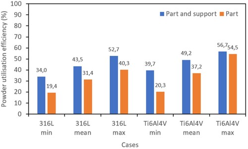
From the obtained data, it can be seen that, concerning the part, 31.4% of the powder used for the entire process is integrated into the model in the case of 316L steel on average. The rest of the powder (68.6%) is not included in the model during the building process. A part of this is used for support building, and another part is realised as powder loss during the process. In the case solidified part (model and support) the powder utilisation efficiency on average was 43.5% and less (56.5%) but almost half of the powder was realised as a loss. The utilisation efficiency range (minimum and maximum) of the powder varied between 19 and 41% in the examined case. On average 37.2% of the Ti6Al4V raw material is used to build the model. If the support is also taken into account, this is almost half of the use of the powder, with an average of 49.2%. The utilisation efficiency range (minimum and maximum) of the powder here varied between 20 and 55% in the examined cases. Comparing the powder utilisation efficiency obtained by steel and titanium alloy, we found that the powder utilisation per mass unit is only slightly more favourable in the case of titanium. Still, it ranges between 20 and 55% for the two materials.
Considering the obtained results further, we get an essential correlation regarding the use of powder because with these ratios, knowing the volume of the model and the support and considering the density of the materials, the amount of powder used in specific cases can be estimated in advance. By using this information, we can estimate the costs related to the powder more accurately, knowing the amount of powder used.
The generally stated advantage of additive manufacturing is that a minimal amount of scrap is generated during the process, significantly improving sustainability. Of course, sustainability is made up of many factors; however, in the case of powder bed technologies, the loss of powder is not negligible but can even be several times the amount of powder used to build the model. Regardless, several factors remain that can be identified as additional advantages in terms of sustainability in the case of additive manufacturing processes. The powder usage results are helpful for equipment users and machine or technology developers.
4. Conclusions
Based on the test results presented, the following conclusions can be made regarding productivity and powder utilisation efficiency related to SLM technology:
The analysis of the printing time data revealed that the recoating time increases slightly with the increase in the filling cross-section ratio, which is related to the cross-section of the laser irradiation. A larger cross-section requires a larger amount of powder. This change can reach 25–28% compared to the recoating time for smaller filling cross-sections.
The laser exposure time increases almost linearly with the filling cross-section. The curve describing the two phenomena intersects at a cross-section filling ratio of 10%. So, in the case of a cross-section filling ratio of around 10%, the recoating time significantly affects the total printing time. In comparison, from a cross-sectional filling ratio of 30% and above, the recoating time only plays a role in a maximum of 10–30%. Determining and knowing the powder recoating time in the case of a specific SLM device is also important because laser exposure or speeding up the powder spreading may be the solution. With the presented methodology, it is also possible to quantify this concretely on other devices.
The developed methodology for the efficiency of powder utilisation is suitable for determining the amount of powder used during the process, used for th printing of the model and the printing of the model and support. Regarding the specific value of powder utilisation efficiency, in a sample of 70 print jobs, the powder utilisation efficiency was 31.4% on average for 316L steel and 43.5% on average for the model and support. In the case of the Ti6Al4V alloy, the degree of utilisation efficiency of the powder used in the printing of the model was, on average, 37.2%, while for the printing of the model and the support, it was, on average, 49.2%. In general, it can be stated that the powder utilisation efficiency range varied between 20 and 55% based on a larger test sample, regardless of materials. In the case of titanium, the powder utilisation efficiency by mass was slightly more favourable than steel. Still, overall, it can be concluded that up to 45 or 80% of the powder is not used during the process, which is essential for users and developers of the technology to consider.
Acknowledgement
Thank you, Gergely Szabados, for his assistance in data collection and Szabolcs Herczeg, for the preliminary evaluation.
Disclosure statement
No potential conflict of interest was reported by the author(s).
Data availability statement
Data is not available at this time.
Additional information
Funding
References
- O'Leary DE. Gartner's hype cycle and information system research issues. Int J Account Inf Syst. 2008;9(4):240–252. doi:10.1016/j.accinf.2008.09.001
- Afadar A, Guzzomi F, Rassau A, et al. Advances in metal additive manufacturing: a review of common processes, industrial applications, and current challenges. Appl Sci. 2021;11(3):1213. doi:10.3390/app11031213
- Ahn DG. Directed energy deposition (DED) process: state of the art. Int J Precis Eng Manuf-Green Tech. 2021;8:703–742. doi:10.1007/s40684-020-00302-7
- Suwanpreecha C, Seensattayawong P, Vadhanakovint V, et al. Influence of specimen layout on 17-4PH (AISI 630) alloys fabricated by low-cost additive manufacturing. Metall Mater Trans A. 2021;52:1999–2009. doi:10.1007/s11661-021-06211-x
- Lores A, Azurmendi N, Agote I, et al. A review on recent developments in binder jetting metal additive manufacturing: Materials and process characteristics. Powder Metall. 2019;62(5):267–296. doi:10.1080/00325899.2019.1669299
- Herzog D, Seyda V, Wycisk E, et al. Additive manufacturing of metals. Acta Mater. 2016;117:371–392. doi:10.1016/j.actamat.2016.07.019
- Wang L, Li Y, Zhou L, et al. Progress in additive manufacturing, additive repair and fatigue evaluation of aviation titanium alloy blades. Mater Res Lett. 2023;11(12):973–1012. doi:10.1080/21663831.2023.2275599
- Tjandra J, Alabort E, Barba D, et al. Corrosion, fatigue and wear of additively manufactured Ti alloys for orthopaedic implants. Mater Sci Technol. 2023;39(18):2951–2965. doi:10.1080/02670836.2023.2230417
- Wiese M, Leiden A, Rogall C, et al. Modeling energy and resource use in additive manufacturing of automotive series parts with multi-jet fusion and selective laser sintering. Procedia CIRP. 2021;98:358–363. doi:10.1016/j.procir.2021.01.117
- Zhou YH, Zhang ZH, Wang YP, et al. Selective laser melting of typical metallic materials: An effective process prediction model developed by energy absorption and consumption analysis. Addit Manuf. 2019;25:204–217. doi:10.1016/j.addma.2018.10.046
- Pan X, Qiu C. Promoting columnar-to-equiaxed transition in AlCoCrFeNi high entropy alloy during selective laser melting by adding Cr3C2. Mater Res Lett. 2022;10(12):788–796. doi:10.1080/21663831.2022.2106798
- Tan C, Zhou K, Ma W, et al. Selective laser melting of high-performance pure tungsten: parameter design, densification behavior and mechanical properties. Sci Technol Adv Mater. 2018;19(1):370–380. doi:10.1080/14686996.2018.1455154
- Colopi M, Caprio L, Demir AG, et al. Selective laser melting of pure Cu with a 1 kW single mode fiber laser. Procedia CIRP. 2018;74:59–63. doi:10.1016/j.procir.2018.08.030
- Chen K, Wang C, Hong Q, et al. Selective laser melting 316L/CuSn10 multi-materials: Processing optimization, interfacial characterization and mechanical property. J Mater Process Technol. 2020;283:116701. doi:10.1016/j.jmatprotec.2020.116701
- Kozak J, Zakrzewski T, Witt M, et al. Selected problems of additive manufacturing using SLS/SLM processes. Trans Aerospace Res. 2021;2021(1):24–44. doi:10.2478/tar-2021-0003
- Pimenov DY, Berti LF, Pintaude G, et al. Influence of selective laser melting process parameters on the surface integrity of difficult-to-cut alloys: comprehensive review and future prospects. Int J Adv Manuf Technol. 2023;127:1071–1102. doi:10.1007/s00170-023-11541-8
- Philo A, Sutcliffe C, Sillars S, et al. A study into the effects of gas flow inlet design of the renishaw am250 laser powder bed fusion machine using computational modelling. Solid Freeform Fabrication 2017: Proceedings of the 28th Annual International; 2017. p. 1203–1219.
- Gunnerek R, Chen Z, Hryha E. Impact of high-productivity process parameters in powder bed fusion – laser beam on microstructure of stainless steel 316L. Eur J Mater. 2023;3:1. doi:10.1080/26889277.2023.2292987
- Dennis Edgard J, Kitashima T, Watanabe M. Effect of scan strategy on the formation of a pure nickel single-crystal structure using a flat-top laser beam via laser powder bed fusion. Sci Technol Adv Mater. 2023;24:1. doi:10.1080/14686996.2023.2201380
- Yao L, Xiao Z, Hoo Z, et al. Mechanism analysis of grain growth dominated by alloy composition gradients during powder bed fusion. Mater Res Lett. 2023;11:(10):814–820. doi:10.1080/21663831.2023.2250826
- An D, Xiao Y, Liu X, et al. Formation of two distinct cellular structures in 316L stainless steel fabricated by micro-laser beam powder-bed-fusion. Mater Res Lett. 2024;12(1):42–49. doi:10.1080/21663831.2023.2292076
- Prashanth KG, Scudino S, Maity T, et al. Is the energy density a reliable parameter for materials synthesis by selective laser melting? Mater Res Lett. 2017;5(6):386–390. doi:10.1080/21663831.2017.1299808
- Gusarov AV, Grigoriev SN, Volosova MA, et al. On productivity of laser additive manufacturing. J Mater Process Technol. 2018;261:213–232. doi:10.1016/j.jmatprotec.2018.05.033
- Sefene EM. State-of-the-art of selective laser melting process: a comprehensive review. J Manuf Syst. 2022;63:250–274. doi:10.1016/j.jmsy.2022.04.002
- Ali H, Ma L, Ghadbeigi H, et al. In-situ residual stress reduction, martensitic decomposition and mechanical properties enhancement through high temperature powder bed pre-heating of Selective Laser Melted Ti6Al4V. Mater Sci Eng A. 2017;695:211–220. doi:10.1016/j.msea.2017.04.033
- Armstrong M, Mehrabi H, Naveed N. An overview of modern metal additive manufacturing technology. J Manuf Process. 2022;84:1001–1029. doi:10.1016/j.jmapro.2022.10.060
- Hitzler L, Janousch C, Schanz J, et al. Direction and location dependency of selective laser melted AlSi10Mg specimens. J Mater Process Technol. 2017;243:48–61. doi:10.1016/j.jmatprotec.2016.11.029
- Liu J, Dong S, Jin X, et al. Quality control of large-sized alloy steel parts fabricated by multi-laser selective laser melting (ML-SLM). Mater Des. 2022;223:111209. doi:10.1016/j.matdes.2022.111209
- Schwerz C, Schulz F, Natesan E, et al. Increasing productivity of laser powder bed fusion manufactured Hastelloy X through modification of process parameters. J Manuf Process. 2022;78:231–241. doi:10.1016/j.jmapro.2022.04.013
- Greco S, Gutzeit K, Hotz H, et al. Selective laser melting (SLM) of AISI 316L—impact of laser power, layer thickness, and hatch spacing on roughness, density, and microhardness at constant input energy density. Int J Adv Manuf Technol. 2020;108:1551–1562. doi:10.1007/s00170-020-05510-8
- Yao D, An X, Fu H, et al. Dynamic investigation on the powder spreading during selective laser melting additive manufacturing. Addit Manuf. 2021;37:101707. doi:10.1016/j.addma.2020.101707
- Drechsel K, Lubkowitz V, Albrecht L, et al. Development of an ultrasonically excited recoating process in laser powder bed fusion to process non-spreadable 316L powder. Powder Technol. 2024;432:119153. doi:10.1016/j.powtec.2023.119153
- Wang L, Li EL, Shen H, et al. Adhesion effects on spreading of metal powders in selective laser melting. Powder Technol. 2020;363:602–610. doi:10.1016/j.powtec.2019.12.048
- Gibbons DW, Govender P, van der Merwe AF. Metal powder feedstock evaluation and management for powder bed fusion: a review of literature, standards, and practical guidelines. Prog Addit Manuf. 2023. doi:10.1007/s40964-023-00484-x
- Lutter-Günther M, Gebbe C, Kamps T, et al. Powder recycling in laser beam melting: strategies, consumption modeling and influence on resource efficiency. Prod Eng Res Dev. 2018;12:377–389. doi:10.1007/s11740-018-0790-7
- Cordova L, Campos M, Tinga T. Revealing the effects of powder reuse for selective laser melting by powder characterization. JOM. 2019;71:1062–1072. doi:10.1007/s11837-018-3305-2
- Yao D, Wang J, Li M, et al. Segregation of 316L stainless steel powder during spreading in selective laser melting based additive manufacturing. Powder Technol. 2022;397:117096. doi:10.1016/j.powtec.2021.117096
- Alamos FJ, Schiltz J, Kozlovsky K, et al. Effect of powder reuse on mechanical properties of Ti-6Al-4 V produced through selective laser melting. Int J Refract Met Hard Mater. 2020;91:105273. doi:10.1016/j.ijrmhm.2020.105273
- Barile C, Casavola C, Paramsamy Kannan V, et al. The influence of AlSi10Mg recycled powder on corrosion-resistance behaviour of additively manufactured components: mechanical aspects and acoustic emission investigation. Archiv Civ Mech Eng. 2022;22:52. doi:10.1007/s43452-022-00375-y
- Chen Z, Xiang Y, Wei Z, et al. Thermal dynamic behavior during selective laser melting of K418 superalloy: numerical simulation and experimental verification. Appl Phys A. 2018;124:313. doi:10.1007/s00339-018-1737-8
- Andani MT, Dehghani R, Karamooz-Ravari MR, et al. Spatter formation in selective laser melting process using multi-laser technology. Mater Des. 2017;131:460–469. doi:10.1016/j.matdes.2017.06.040
- Bidare P, Bitharas I, Ward RM, et al. Fluid and particle dynamics in laser powder bed fusion. Acta Mater. 2018;142:107–120. doi:10.1016/j.actamat.2017.09.051
- Keaveney S, Shmeliov A, Nicolosi V, et al. Investigation of process by-products during the Selective Laser Melting of Ti6AL4V powder. Addit Manuf. 2020;36:101514. doi:10.1016/j.addma.2020.101514
- Guo Q, Zhao C, Escano LI, et al. Transient dynamics of powder spattering in laser powder bed fusion additive manufacturing process revealed by in-situ high-speed high-energy x-ray imaging. Acta Mater. 2018;151:169–180. doi:10.1016/j.actamat.2018.03.036
- Kjer MB, Pan Z, Nadimpalli VK, et al. Experimental analysis and spatial component impact of the inert cross flow in open-architecture laser powder bed fusion. J Manuf Mater Process. 2023;7(4):143. doi:10.3390/jmmp7040143
- Young ZA, Guo Q, Parab ND, et al. Types of spatter and their features and formation mechanisms in laser powder bed fusion additive manufacturing process. Addit Manuf. 2020;36:101438. doi:10.1016/j.addma.2020.101438
- Gunenthiram V, Peyre P, Schneider M, et al. Experimental analysis of spatter generation and melt-pool behavior during the powder bed laser beam melting process. J Mater Process Technol. 2018;251:376–386. doi:10.1016/j.jmatprotec.2017.08.012
- Sutton AT, Kriewall CS, Leu MC, et al. Characterization of laser spatter and condensate generated during the selective laser melting of 304L stainless steel powder. Addit Manuf. 2020;31:100904. doi:10.1016/j.addma.2019.100904
- Ladewig A, Schlick G, Fisser M, et al. Influence of the shielding gas flow on the removal of process by-products in the selective laser melting process. Addit Manuf. 2016;10:1–9. doi:10.1016/j.addma.2016.01.004
- Anwar AB, Pham Q-C. Study of the spatter distribution on the powder bed during selective laser melting. Addit Manuf. 2018;22:86–97. doi:10.1016/j.addma.2018.04.036
- Anwar AB, Pham Q-C. Selective laser melting of AlSi10Mg: effects of scan direction, part placement and inert gas flow velocity on tensile strength. J Mater Process Technol. 2017;240:388–396. doi:10.1016/j.jmatprotec.2016.10.015
- Shen H, Rometsch P, Wu X, et al. Influence of gas flow speed on laser plume attenuation and powder bed particle pickup in laser powder bed fusion. JOM. 2020;72:1039–1051. doi:10.1007/s11837-020-04020-y
- Ferrar B, Mullen L, Jones E, et al. Gas flow effects on selective laser melting (SLM) manufacturing performance. J Mater Process Technol. 2012;212(2):355–364. doi:10.1016/j.jmatprotec.2011.09.020
- Guoqing Z, Junxin L, Xiaoyu Z, et al. Optimized design and key performance factors of a gas circulation filtration system in a metal 3D printer. Sci Rep. 2022;12:14267. doi:10.1038/s41598-022-18524-x
- Pauzon C, Hoppe B, Pichler T, et al. Reduction of incandescent spatter with helium addition to the process gas during laser powder bed fusion of Ti-6Al-4 V. CIRP J Manuf Sci Technol. 2021;35:371–378. doi:10.1016/j.cirpj.2021.07.004
- Anwar AB, Ibrahim IH, Pham Q-C. Spatter transport by inert gas flow in selective laser melting: A simulation study. Powder Technol. 2019;352:103–116. doi:10.1016/j.powtec.2019.04.044
- Ficzere AHP. Finite element modeling of additive manufacturing in case of metal parts. Period Polytech Transp Eng. 2022;50(4):330–335. doi:10.3311/PPtr.19242
- Zhang X, Tuffile C, Cheng B. Computational modeling of the inert gas flow behavior on spatter distribution in selective laser melting. Solid Freeform Fabrication 2019: Proceedings of the 30th Annual International, 1362-1372, 2019, Austin, TX, USA; 2019.
- Lutter-Günther M, Hofmann A, Hauck C, et al. Quantifying powder losses and analyzing powder conditions in order to determine material efficiency in laser beam melting. Appl Mech Mater. 2017; 856:231–237. doi:10.4028/www.scientific.net/amm.856.231