
 ?Mathematical formulae have been encoded as MathML and are displayed in this HTML version using MathJax in order to improve their display. Uncheck the box to turn MathJax off. This feature requires Javascript. Click on a formula to zoom.
ABSTRACT
In this study, an underwater in-situ induction heating treatment (UIHT)was carried out to modulate microstructure and improve the performance of underwater laser-directed energy deposition (ULDED) samples. The results showed that the redistributive behaviour of alloying elements during the UIHT process promoted the α′→α + β transition. Furthermore, the high temperature enabled dislocation motion, and the heterogeneous dislocations cancelled each other out, causing a decrease in the dislocation density. Notably, the changes in mechanical properties were primarily attributed to the changes in α grain size and dislocation density. The decomposition of martensite α′, characterised by a high dislocation density, elevated the likelihood of intergranular slip. The homogeneously dispersed α + β microstructure promoted coordinated deformation during slip, enhancing the ductility of the specimen and reducing the anisotropy of its mechanical properties. This study offers valuable guidelines for microgroup tailoring and property modulation of ULDED-repaired titanium alloys.
1. Introduction
Titanium alloys have been extensively utilised in marine engineering due to their excellent combination of high specific strength, excellent fracture toughness, and corrosion resistance [Citation1–3]. Ti-6Al-4 V, a prototypical (α + β) two-phase titanium alloy, exhibits the thermal stability inherent in α-alloys and the enhanced characteristics typical of β-alloys following heat treatment, demonstrating exceptional overall properties. Hence, Ti-6Al-4 V is considered a promising material to address common issues, such as insufficient buoyancy reserve and poor structural safety and reliability during long-term underwater use of deep-sea equipment [Citation4]. However, harsh marine environments easily damage the surface, and cause the failure of underwater structural components. Therefore, underwater on-site maintenance and repair technology is crucial to ensuring the safety of marine engineering components in service [Citation5,Citation6].
In recent years, underwater laser additive manufacturing has rapidly emerged as a promising technology for in-situ repair of marine engineering components, owing to its notable advantages including high repair accuracy and exceptional performance. This technology is divided into wet and local dry methods based on different environments. Underwater wet laser energy deposition is a way to directly produce coatings on the substrate surface in water environment with advantages of flexible operation and low equipment requirements, but the relevant studies have demonstrated that this method failed to carry out while the water depths exceed 8 mm as the water and the laser induced plasma intensively attenuated the laser beam [Citation7]. Even if a protective coating is used to prevent the intrusion of high-speed water into the melt pool, the experimental water depth of this method is limited to 20 mm [Citation8,Citation9]. In contrast, the underwater local dry laser energy deposition technique creates a stable local dry cavity around the repair area using a drainage device, which allows high quality underwater coatings with little restriction by water depth. Based on the state of the filling material, the current underwater local dry laser-directed energy deposition technology (UDED) is categorised into powder feeding and wire feeding. Sun et al. employed powder melting laser additive technology to prepare repair coatings on 18Ni-300 steel plates [Citation10], Ti-6Al-4 V alloy [Citation11], HSLA-100 steel [Citation12], and 316LN stainless steel [Citation13]. According to their findings, the water quenching effect increased the cooling rate during the UDED process, promoting martensite formation. The metal deposited underwater presented high-density crystal defects and considerable residual stress. The microhardness of the sample was higher than that of the air-directed energy deposition sample. Additionally, this UDED technology based on coaxial powder delivery has a low powder utilisation rate (50%∼80%). This low powder density leads to the formation of holes and other defects in the repaired layer. Moreover, the minor heat input is often accompanied by a more significant cooling rate, which makes it susceptible to the formation of columnar crystals and non-equilibrium phases.
The wire-feeding UDED technology has the advantages of high material utilisation, high deposition efficiency, and low porosity defect tendency, considering the cost requirements, deposition efficiency, and forming quality. Sano et al. utilised the UDED technique to achieve a well-formed repair layer on the inner wall of 316L stainless steel pipe, thereby reducing the sensitivity of stress corrosion cracks on the base metal surface [Citation14]. Fu et al. fabricated Ti-6Al-4 V alloy [Citation15–17] and 304 stainless steel [Citation18] with uniform forming, demonstrating no porosity or other defects at a water depth of 0.06 m utilising wire-feeding underwater laser cladding technology. According to their findings, the rapid cooling effect caused by the water environment is primarily responsible for the increased number of martensites. Furthermore, the differences in the inherent thermal cycling in the ULDED process caused changes in grain size in the deposition region and microstructure inhomogeneity.
For the Ti-6Al-4 V alloy, the rapid remelting and solidification process of additive manufacturing resulted in the generation of a large temperature gradient and cooling rate within the molten pool, along with the formation of a sizeable columnar crystal structure in the sample [Citation19,Citation20]. The additional cooling effect of the water environment during the ULDED process and the complexity of the additive manufacturing thermal process contribute to the heterogeneity of the sample microstructure. This results in the anisotropy of the sample properties and also reduces the plastic toughness and damage tolerance of the additively manufactured materials [Citation21,Citation22].
Currently, researches on laser additive technology primarily focus on regulating process parameters. Despite the efforts of scholars to achieve isotropy by adjusting process parameters and scanning strategies, the expected results have yet been fully realised. Notably, heat treatment is more commonly utilised to alter the original microstructures of additive parts to meet usage specifications [Citation23].
To eliminate stress, stabilise the structure, and improve the performance of AM Ti-6Al-4 V parts formed, Wu et al. systematically analysed the effects of heat treatment on texture evolution and microhardness across a temperature range of 300°C to 1020°C. The findings revealed that subtracting heat treatment does not modify the morphology of the original columnar β grain; however, it can decompose the acicular α’ martensite into α sheets [Citation24]. Xu et al. examined the impact of heat treatment on the microstructure of Ti-6Al-4 V samples prepared by laser additive manufacturing (LAM) for temperatures ranging between 350 and 930°C. According to the findings, the decomposition of αʹ martensite occurred at temperatures as low as 400°C. The study demonstrated that the heat treatment time, accumulated from the thermal cycling effect during the selective laser melting (SLM), is adequate to achieve a near-complete transformation of αʹ martensite into ultrafine lamellar (α + β) [Citation25]. Kaschela et al. investigated the micro/nanostructure evolution (αʹ martensite phase decomposition) during the heat treatment process of a Ti-6Al-4 V alloy prepared by additive manufacturing and elucidated the transformation kinetics. Based on the results, a phase transformation mechanism is proposed, involving the accommodation or substitution of Al, V, and Ti atoms in the crystal lattice [Citation26]. Further research reveals that the transition from an αʹ phase to an α + β phase causes a release of the residual stress and improves the ductility of conventionally annealed AM titanium alloys [Citation27,Citation28]. Vilaro et al. examined the impact of conventional and optimised heat treatments on the mechanical behaviour of parts. According to their observations, the gradual decomposition of αʹ, achieved by annealing at 850°C/2 h followed by air cooling, produced an increase in hardness compared to annealing at lower temperatures [Citation29].
Conversely, Ter Haar and Becker claimed that duplex annealing (part held at 950°C for 4 h, and followed by water quenching) yields superior tensile properties and bi-modal microstructure compared to standard annealing strategies [Citation30]. Furthermore, considering the complexity of the shape of the heating part and the flexibility of the working condition, Shen et al. employed in-situ induction heating for the heat treatment of arc additive manufacturing samples and established a finite element model of the thermal stress field during the whole process of induction heating. As per the findings, induction heat treatment (IHT) improved the stress distribution in the component and eased the stress concentration [Citation31]. Hence, it is feasible to perform post-heat treatment on laser additive samples to homogenise microstructure and improve properties.
Current studies on the heat treatment of additively manufactured metals have been conducted in the air environment. However, there have been no reports on modulation mechanism and method of the microstructure and properties within ULDED samples. In this study, ULDED samples were heat-treated based on the UIHT platform aimed at regulating the microstructure and dislocation of the Ti-6Al-4 V part manufactured by ULDED, further improving the performance and significantly eliminating the anisotropy property. Notably, this technique was developed alongside wire-based underwater laser-directed energy deposition. Furthermore, the elemental redistribution behaviour during the UIHT process and the relationship between microstructural evolution and properties were analysed, providing valuable insights into the modulation of the properties of ULDED Ti-6Al-4 V alloys.
2. Experimental procedure
2.1. Experimental materials
The chemical composition and mechanical property parameters of Ti-6Al-4 V alloy were shown in and . The Ti-6Al-4 V wire, with a diameter of 1 mm, was employed to melt onto a substrate of the same material with a thickness of 10 mm. The microstructure of the base material was shown in . Under the optical microscope, the microstructure of Ti-6Al-4 V presents α + β phase structure, and the dark β phase is evenly distributed among the equiaxed α phase.
Figure 1. SEM morphology of Ti-6Al-4 V.
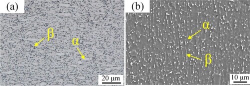
Table 1. Chemical composition of Ti-6Al-4 V (ωt%).
Table 2. Mechanical properties of Ti-6Al-4 V.
2.2. Experimental setup
The experimental platform consists of a ULDED station and an induction heating station, and the schematic diagrams of the ULDED and UIHT process are illustrated in . In the ULDED station, the industrial robot can realise multi-DOF manufacturing, and a semiconductor laser (WFD5000) with a maximum power of 5 kW outputs beam energy to melt the wire. High-purity argon gas is flown through the ULDED nozzle to form an air curtain that removes moisture from the surface of the substrate and creates a localised drying cavity. Before ULDED, the substrate was positioned in the water tank, with a water depth of approximately 60 mm. Ti-6Al-4 V samples were deposited using the process parameters shown in .
Figure 2. Schematic diagrams of the ULDED and UIHT process.
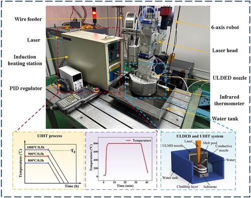
Table 3. Typical processing parameters of the ULDED Ti-6Al-4 V samples.
Upon completion of the ULDED procedure, the cooled samples were heat-treated in-situ utilising an induction heating station, and the protective gas in the drain torch was continuously maintained to create a locally dry environment. The induction heating station included induction heating power supply, induction coil, water chiller and infrared thermometer. During the UIHT process, the infrared thermometer monitored the temperature of the Ti-6Al-4 V sample in real time and transmitted the real-time collected data to the PID regulator, which output signals to adjust the induction heating process parameters according to the difference between the real-time temperature and the set temperature in order to maintain constant temperature heat treatment of the sample. After holding for a specific time, the sample was cooled to room temperature at a rate of 100°C / min.
2.3. Microstructure characterisation and performance test
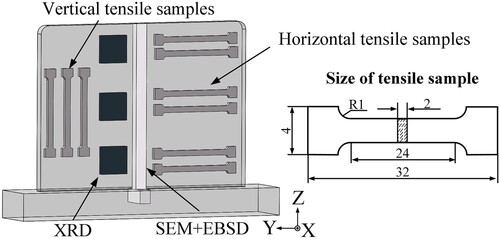
The sampling methods for metallographic structure, mechanical properties testing, specimens are illustrated in . The process involved grinding and mechanical polishing of the metallographic samples, which were then etched with Kroll chemical reagents. The macroscopic structure of the cross-section of the Ti-6Al-4 V sample was observed using an optical digital microscope (OLYMPUS DSX510). The microstructure of the sample was analysed using a scanning electron microscope (MERLIN Compact) and transmission electron microscope (FEI Talos F200X). In preparation for the tensile test, the surface of the specimen was wet sanded with 400-grit silicon carbide sandpaper. The tensile tests were conducted on flat dog-bone-shaped specimens with a 1 mm/min moving speed on a universal material testing machine. A manual turret microhardness tester characterised the hardness of the additive sample. The load was 1.96 N, and the loading time was 10 s. The adjacent hardness collection points were separated by 0.3 mm, and the average values were measured three times along the sample height direction from top to bottom.
Figure 3. Test position of the sample.
3. Results
3.1. Microstructures
3.1.1. Phase composition
displayed the X-ray diffraction patterns of the as-built samples and the samples treated with induction heating. The as-built samples exhibited typical α/αʹ martensitic diffraction patterns. Here, the diffraction patterns of α phase and αʹ almost coincided with each other owing to their closely packed hexagonal lattice structures (HCP) with similar lattice constants. Conversely, the diffraction peaks of the β phase, characterised by the BCC lattice structure, were weaker, suggesting an insufficient content of the β phase in the ULDED samples. listed diffraction peak of the α/αʹ, the half-width of the α/αʹ diffraction peak of the as-built sample is higher than that of the sample treated with induction heating, indicating αʹ decomposition during induction heating. The rapid solidification process of the ULDED inhibited vanadium diffusion, leading to a higher retention of the β-stable element vanadium αʹ than in the equilibrium α phase. Consequently, αʹ crystal structure deformed and the diffraction peak widened. In the UIHT-800°C sample, the peak of the β phase (110) was higher than that in the as-built sample, demonstrating the transformation process of martensite αʹ to β during induction heating. Moreover, it was observed that the β content further increased when the sample heating temperature increased to 900°C. However, the increase in β content was not apparent when the samples were heated above the β transition temperature (Tβ). The comparison of the {100} and {002} diffraction peaks of α/αʹ showed that the reflection peaks gradually widened and shifted towards lower 2θ values with increasing induction heating temperature. This effect was indicative of the increase in interplanar crystal spacing and the reduction in residual compressive stress in the constructed sample.
Figure 4. XRD spectra obtained of UIHT Ti-6Al-4 V.
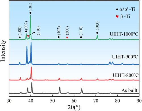
Table 4. The half-width of the α/α’ diffraction peak.
3.1.2. Grain and microstructure transformation with UIHT
depicted the cross-sectional morphology and microstructure in different areas of the as-built sample. Fine equiaxial grains were observed in the top thin-layer region of the sample, and columnar previous β particles grew along the tectonic direction in the other parts of the sample, whereas the columnar prior β-grains grew along the tectonic direction in other parts of the sample. This phenomenon occurred because, during the initial stages of the ULDED process, heat dissipation occurred directly from the bottom deposition layer near the substrate into the two-dimensional plane of the substrate, which was in direct contact with the aqueous environment. This resulted in the generation of a larger thermal gradient compared to the other parts of the substrate, causing the columnar grains to nucleate on the fusion line and grow in the opposite direction of the heat flow. Nevertheless, the heat loss mode gradually changed to one-dimensional heat dissipation along the building direction of the structure in the central deposition area. During deposition, the input of laser energy caused the remelting of equiaxed grains on the surface of the pre-deposited layer. The solid-liquid interface advanced in the form of planar grains under the influence of a large thermal gradient and eventually grew into coarse columnar crystals. The top position of the sample underwent relatively weak thermal cycling due to the absence of subsequent heat input. In addition to being transferred to the finished deposited layers, heat could also be lost to the air. Moreover, the solidification rate of the molten pool was higher at this point, leading to the formation of an equiaxial crystalline zone of thinner thickness at the surface.
Figure 5. Cross-sectional morphology and microstructure of different areas of as-built sample:(a) and(b) upper area; (c) and(d)middle area; (e) (f) bottom area.
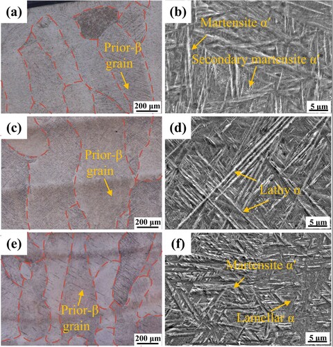
The microstructure of the as-built sample was primarily composed of elongated acicular martensite αʹ, lathy α, and lamellar α. Besides, the microstructure distribution exhibited heterogeneity. The equilibrium transition from β phase to α phase during the ULDED process depended on the diffusion of elements and took a long time; this transition was inhibited in the deposition process due to the high cooling rate. The transformation of the crystal structure of the β-phase proceeded normally, resulting in the formation of the martensitic αʹ phase in the sample. Generally, there were numerous defects in the lattice of the martensite αʹ phase, which wa in a metastable state. The metastable phase ultimately returned to the more stable α + β structure on heating above the martensitic transition temperature. Consequently, the generated martensite αʹ cannot be completely retained in the subsequent cladding process but decomposed into α and β phases under intrinsic heat treatment. Due to the different cooling rates and the number of thermal cycles in different passes, the bottom experienced a rapid cooling rate. Moreover, without subsequent heat input at the top, the martensitic αʹ phase was preserved.
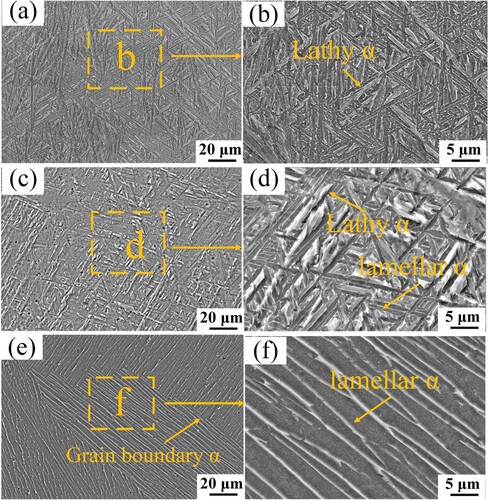
illustrated the scanning electron microscopy (SEM) morphology of the samples after UIHT treatment. The elongated acicular martensite transformed into a mixture of α and β under UIHT-800°C conditions. The α phase was present in a fine acicular form, while the original lamellar α phase grew following heat treatment. Notably, the α phase in the UIHT-900°C sample continued to thicken with increasing temperature, and the length-diameter ratio further decreased. This result aligned with the finite element calculation by Katzarov et al. [Citation19], which predicted the coarsening of the α and β phase morphologies during heat treatment at elevated temperatures below the β transition temperature. Moreover, coarse lamellar colonies predominantly grew inwardly from the prior columnar β grain boundaries in the samples, as the UIHT temperature reached 1000°C, and some even grew across entire prior β grains.
Figure 6. Microstructure of UIHT samples: (a) and (b) UIHT-800°C; (c) and (d) UIHT-900°C; (e) and (f) UIHT-1000°C.
illustrated the electron backscatter diffraction (EBSD) inverse pole figure (IPF) mappings and pole figures (pf) on the XOZ plane of the as-built and UIHT samples. Similar columnar morphology was observed under various conditions. As depicted in a, the ULDED as-built sample exhibited an acicular martensitic αʹ microstructure. The aspect ratio of αʹ was more significant compared to the additive samples from the onshore environment [Citation32,Citation33]. The exceedingly high cooling rates facilitated the growth and orientation of these needlelike structures during ULDED. The closer orientation relationship of the neighbouring grains was attributed to the occurrence of the β→α + αʹ phase transformation process during solidification. Moreover, the β and α-phases, before and after the transformation, maintained the Burgers orientation relationship (BOR) of {110}β // {0001}α and <111>β // <11–20>α. Additionally, the 12 α/αʹ-phase transitions formed in β → α/αʹ grains during the rapid phase transformation process due to water cooling present a more pronounced distribution of preferential orientations. The lamellar width was considerably more uniform compared to the as-built sample following the UIHT procedure. Moreover, the aspect ratio reduced significantly, aligning with the SEM observations in .
Figure 7. Inverse pole figure maps (a-d) and pole figures (e-h) of the samples: (a) and (e) As-built, (b) and (f) UIHT-800°C, (c) and (g) UIHT-900°C, (d) and (h) UIHT-1000°C.
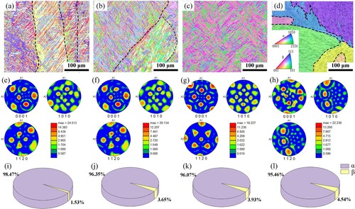
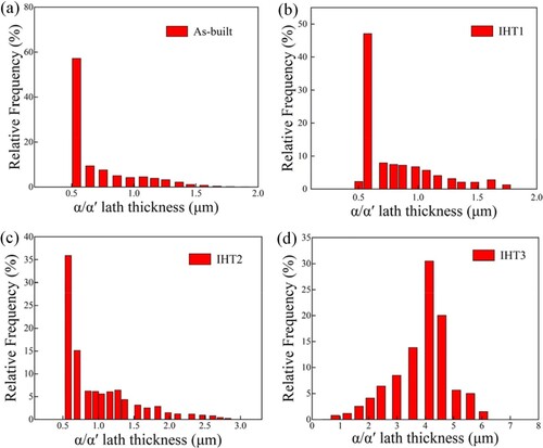
Furthermore, apparent changes were observed in the α-phase morphological size. displayed the distribution of grain size. The as-built sample underwent rapid cooling, consistent with the findings of the previous SEM analysis, leading to the formation of intensely fine αʹ grains with an average size of 0.718 µm. The coarsening of α was further verified by the difference in the average size of the α phase following the UIHT process under various conditions, as illustrated in parts a, b, and c of . The coarsening degree of α was positively correlated with the heating temperature. The UIHT-1000°C sample exhibited the largest average α phase size of 4.163 µm. The α-pf of the constructed sample presented a firm HCP texture (the maximum texture index was 24.513). On the contrary, the maximum texture index of the UIHT-900°C sample decreased to 18.227, suggesting that the appropriate UIHT temperature can weaken the texture and make the crystal orientation distribution more uniform.
Figure 8. Grain size distribution of α'/α laths: (a) As-built, (b) UIHT-800°C, (c) UIHT-900°C, (d) UIHT-1000°C.
As depicted in , the morphology and distribution characteristics of each phase of the as built sample, as well as the heterogeneous substructures, such as the dislocation network in each sample, were further analysed through transmission electron microscopy (TEM). As displayed in (a), acicular α′ martensite with various orientations in the as-built specimen was distributed throughout the grain. (b) revealed a high density of dislocations in the acicular α′ phase, especially parallel dislocations at grain boundaries, indicating the presence of significant internal residual stresses in the martensite. The motion of dislocations was impeded, and their gradual aggregation led to the formation of dislocation walls.
Figure 9. TEM micrograph of the as built sample.
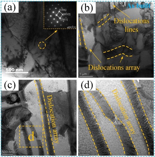
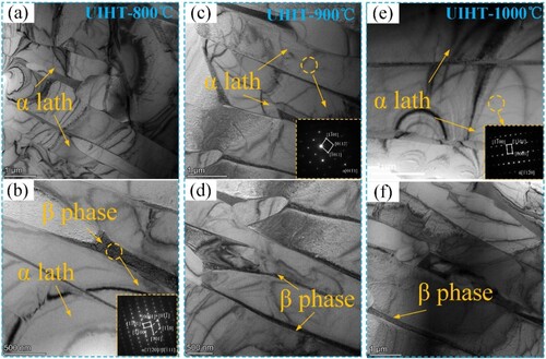
In the UIHT sample illustrated in (a–f), along with the analysis of electron diffraction (SAED) maps of selected regions, it was observed that the α-phase and β-phase exhibited an [Citation10–19] α // [−111] β orientation relationship, consistent with the BOR. Furthermore, the equilibrium transformation of the α + β mixed microstructure was distributed in the α-layer with an increase in lamellae size. Additionally, both the dislocation density and the number of dislocation walls in the UIHT samples decreased. Besides, most dislocations were concentrated on the boundaries of the α-grains, indicating that UIHT promoted dislocation annihilation.
Figure 10. TEM micrograph of the UIHT samples: (a) and (b) UIHT-800°C, (c) and (d), UIHT-900°C, (e) and (f)UIHT-1000°C.
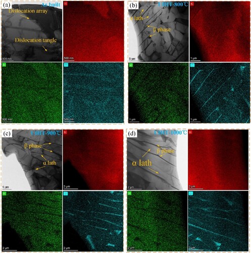
The elemental surface distribution of the samples was illustrated in . Analysis revealed a slight elemental bias between the αʹ phases during ULDED. Following the UIHT process, a discernible discrepancy in the concentration of Al and V elements between the α and β phases of the specimen was observed. Specifically, the V content in the β phase exceeded that in the α phase, while conversely, the Al content was lower in the α phase compared to the β phase. These findings suggest the occurrence of elemental redistribution during the UIHT process.
Figure 11. TEM micrograph of the sample: (a) As-built, (b) UIHT-800°C, (c) UIHT-900°C, (d) UIHT-1000°C.
3.2. Mechanical properties
3.2.1. Tensile properties
depicted the vertical and horizontal tensile properties of the deposited metals under various UIHT conditions. Notably, the horizontal tensile strength (UTS-H) was higher (967.4 MPa), and the elongation (EL-H) was lower (6.89%), whereas the vertical tensile strength (UTS-V) and elongation (EV) were significantly directional. Columnar crystals grew along the direction of deposition height during the ULDED process and passed through the multilayer cladding layer. This resulted in a higher number of columnar grain boundaries along the horizontal direction than in the vertical direction. The grain boundary dislocations accumulated as a consequence of the blocking effect of the grain boundary on dislocation slip, enhancing the tensile strength of the material [Citation34]. Moreover, brittleness tended to be higher due to the increased number of defects at the grain boundaries, which was responsible for the lower EL-H. The ductility of the sample was improved following the UIHT process. Under the UIHT-800°C condition, both EL-H and EL-V experienced an increase of 1.42% and 0.93%, respectively. The EL-H of the samples continued to increase to 9.67% under UIHT-900°C conditions and 9.96% along the EL-V of the samples. The anisotropy of mechanical properties was quantitatively described by the following formula [Citation35]:
(1)
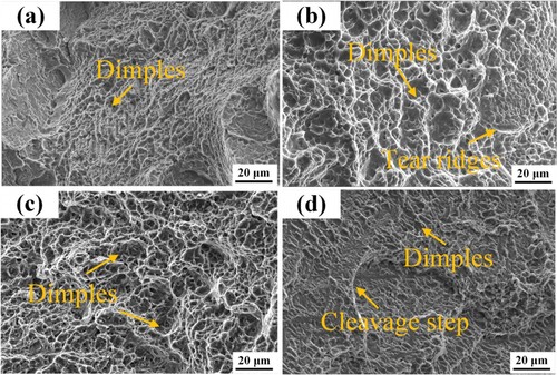
(1) TH and TV respectively represents the mechanical properties of the horizontal and vertical specimens, such as tensile strength and ductility. After undergoing high-temperature treatment, the IPA values of tensile strength and ductility decreased from 10% and 14% after construction to 4% and 3%, respectively. Furthermore, the fracture morphology of transverse tensile specimens was observed, and the differences in tensile properties of UIHT specimens were subsequently analysed. (a) depicted the tensile fracture morphology of the as-built sample. It was essential to note that the fracture surface exhibited cleavage steps, cleavage planes, tear edges, and dimples. Moreover, the fracture presented mixed characteristics of ductile fracture and brittle fracture. The presence of equiaxed ligamentous fossae of different sizes and depths in the UIHT-800°C and UIHT-900°C samples signified typical ductile fracture. The UIHT −1000°C treatment resulted in a decrease in the number and depth of the ligamentous fossae, with a corresponding decrease in plasticity.
Figure 12. Tensile properties of the sample.
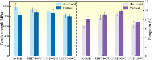
Figure 13. The fracture morphology of the samples: (a) As-built, (b)UIHT-800°C, (c) UIHT-900°C, (d) UIHT-1000°C.
3.2.2. Microhardness
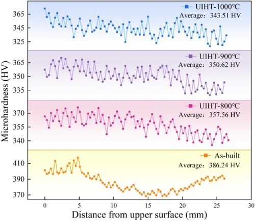
illustrated the microhardness distribution of the samples along the vertical direction. The hardness of both the top and bottom of the as-built sample was higher and exhibited a shallow ‘V’ shape. The average hardness of the sample was reduced following the UIHT procedure, resulting in a more uniform hardness distribution. Notably, the average hardness of the samples decreased as increasing UIHT temperature. Nevertheless, the hardness values in the top region remained elevated, possibly due to the unavoidable oxidation of the sample surface during the UIHT process.
Figure 14. Gradient distribution of sample microhardness: (a) As-built, (b)UIHT-800°C, (c) UIHT-900°C, (d) UIHT-1000°C.
4. Discussion
4.1. Microstructure evolution during the UIHT
The microstructures of AM Ti-6Al-4 V parts, fabricated under various heat sources, process parameters, and fabrication strategies in ambient air, predominantly comprise α-phase in the form of lumps, strips, and flakes, forming basket weave, agglomerate, or widmannstatten structure, along with acicular martensite α′ in various size scales and residual β-phase [Citation18–24,Citation26,Citation27,Citation29,Citation35]. Compared to the Ti-6Al-4 V samples deposited by LDED in air environment, the ULDED samples presented more acicular martensite α′ in different sizes and dimensions as reported by Fu et al, which could be attributed to the distinctive heat dissipation pathway during the ILDED and ULDED processes. The heat dissipation of the LDED sample included convective heat dissipation at the sample surface, radiative heat dissipation, and conduction heat dissipation inside the sample. As the ILDED process proceeded, the temperature of the substrate and deposited parts gradually increased due to heat accumulation, resulting in a smaller thermal gradient (G) inside the sample. In contrast, for ULDED samples, the gas-liquid two-phase heat dissipation greatly increased the heat dissipation rate and accelerated the rapid cooling of the ULDED sample, leading to a larger G during the ULDED process. Since grain morphology is determined by the solidification rate (R) at the solid-liquid interface and G, the increase in G/R promotes the formation and growth of columnar grains [Citation30,Citation31,Citation36,Citation37]. As a result, more coarser columnar crystals formed in ULDED samples compared to ILDED samples. In addition, the cooling rate of the ULDED sample was much larger than that of the ILDED sample during the solid-state phase transition due to the cooling effect of the forced cooling of the substrate by the aqueous environment. Consequently, the equilibrium transformation of the β-phase was suppressed, leading to the retention of more elongated needle-like martensite α′ within the sample The presence of coarse columnar crystals led to the anisotropy of the ULDED samples, while the more content of martensite α′ led to the high strength and low plasticity property characteristics of the Ti-6Al-4 V samples.
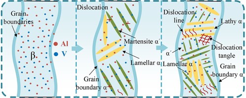
illustrated the microstructure transformation mechanism in ULDED. In the ULDED process, the convection effect of the water environment on the substrate facilitated the rapid cooling of the deposited part, forming a steep temperature gradient in the ULDED sample. The steep thermal gradient and high cooling rate caused the rapid solidification of the molten pool and the solid-phase transition. Consequently, the β-stabilising element (V) lacked sufficient time for diffusional precipitation during rapid cooling of the β-phase from high temperatures. This resulted in the formation of the elongated acicular ultra-solvable martensite α′ via nondiffusive shear transformation. Although subsequent heat treatment of the deposited layer facilitated the α′→ α + β transformation, the rapid cooling characteristic of the ULDED process prevented the completion of this transition. Correspondingly, a significant number of α′ phases were still retained in the as-built sample. This delicate martensitic α′ phase, depicted in , contains a high density of crystal defects, including laminae and dislocations. These defects accommodate the shape strain and volume change caused by the β →α′ transformation [Citation38]. Due to the effect of intrinsic heat treatment during ULDED, differences in the thermal history of previously deposited layers led to variations in α/α′ grains and substructures, resulting in inhomogeneities in the microstructure.
Figure 15. Schematic diagram of microstructure evolution of UIHT samples.
During the UIHT treatment of the as-built specimens, the Al and V atoms in the lattice recieved sufficient energy to diffuse and accommodate in order to reduce the internal residual stresses. This finding aligned with the XRD analyses, indicating the occurrence of stress relaxation during the heating process. displayed the elemental redistribution process during the heating stage of the UIHT process of the Ti-6Al-4 V alloy. During the heating process, the V atoms diffused from the martensite α’ centre to the α/α’ interface [Citation26,Citation39]. However, as illustrated in a, the Al atoms diffused from the α/α’ interface towards the adjacent centres of the two phases. It was noted that, as the diffusion proceeds, the V elements become enriched at the boundaries [Citation40]. As presented in b, this phenomenon promoted the nucleation of the β-phase at the interfaces. Moreover, the numerous pre-existing dislocations within the alloy served as the driving force for the growth of the α and β phases, with the dislocations acting as high diffusivity paths for alloying elements [Citation36]. Thus, it can be inferred that during the UIHT process, the opposite-sign dislocations in the α’ tended to annihilate, reducing the strain energy of the samples. This phenomenon was different from the results obtained by other modification methods [Citation37,Citation41], where the dislocation density in the sample tended to decrease after the UIHT procedure. Besides, the annihilation process was beneficial to the movement of alloying elements. With increasing temperature during the UIHT process, the elemental diffusion continued, causing the β-phase to grow gradually [Citation42]. The α→β transition lowered the proportion of the α-phase and, correspondingly, increased the ratio of the β-phase. Given the increase in the β-phase, the enriched V elements must be distributed into the β-phase with a rapidly increasing volume fraction. Hence, the change in its average content was not apparent. The original α-phase was enriched with Al elements, and the content of Al elements increased with the significant decrease in the α-ratio, enhancing the stability of the α-phase at high temperatures. Therefore, the untransformed α-phase remained in the Ti-6Al-4 V alloy during the holding phase at UIHT (see c). Moreover, related studies confirmed that the annealing time of 1 h 40 min was insufficient to achieve a complete α→β transformation in Ti-6Al-4 V alloy at 1000°C [Citation43].
Figure 16. Schematic diagram of microstructure evolution of DLDED samples.
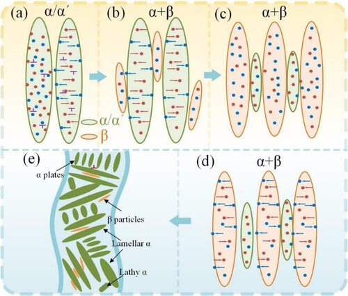
During the UIHT cooling process, the V atoms diffused from the centre of the β-phase to the boundary (d), and the slow cooling rate ensured that the diffusion proceeded adequately. Notably, the resistance to β-phase lattice reorganisation decreased as the content of stabilising elements in the β-phase decreased, promoting a full β → α transition, as depicted in e. The α grains grew towards the periphery, and the α + β equilibrium phase was attained after cooling to room temperature. In addition, different parts of the samples were uniformly heated during the UIHT procedure, and the uniformity of the above elemental redistribution and dislocation migration behaviours ameliorated the microstructural inhomogeneities caused by the differences in thermal cycling and cooling rates.
In contrast to other hybrid additive manufacturing techniques (e.g. hybrid laser impact peening with laser directed energy deposition), the as-built samples do not incorporate the corresponding large deformation treatments, and therefore β-grain refinement due to recrystallization does not take place during the UIHT process [Citation44,Citation45]. Based on the mechanism of UIHT promoting the diffusion of elements, we further analysed the impact of temperature on the α grain size. The total interfacial energy of the large-size α-lath was smaller compared to the small α-lath. Consequently, energy minimisation served as the driving force for the coarsening of α, with solute atom diffusion playing a supporting role in the process. Thus, the growth of the α-phase was spontaneous under sufficient diffusion time and temperature conditions [Citation26,Citation46]. During in situ heat treatment, the diffusion rate of α-stabilized elements accelerated with increasing temperature, as represented by the following diffusion EquationEquation (2)(2)
(2) :
(2)
(2) Here, C∞ denotes the concentration of the saturated solution, s denotes the inter-phase surface tension, ν represents the atomic volume of the solute, k is the gas constant, and T denotes temperature.
According to EquationEquation (2)(2)
(2) , the equilibrium concentration of α-stable elements at the α-lath boundary was a function of the grain curvature radius R and was inversely proportional to it. As per the theory, the equilibrium concentration of α-phase stable elements at small α-plate interfaces was notably more significant than at large α-plate interfaces. Furthermore, α-phase stable elements gradually diffused into larger α-phase groups. The increase in temperature during the UIHT process promoted the diffusion of elements, accelerating the rate of α-coarsening [Citation47,Citation48]. Hence, compared with the as-built samples, the α-phase of the UIHT samples presented varying degrees of coarsening, with coarsening positively correlated with temperature.
4.2. Influence mechanisms of microstructure and dislocation on performance
It is well known that parameters like composition and microstructure are vital in determining material properties. The microstructure of the as-built samples was determined by the cooling rate and temperature gradient, while the inhomogeneity of the microstructure led to anisotropy in their properties. Following UIHT, the morphology and distribution of the microstructures changed, leading to substantial changes in the mechanical properties of the UIHT samples compared to the as-built samples.
| (1) | Changes in phase content | ||||
| (2) | Dislocation density | ||||
From EquationEquation (3)(3)
(3) , the slip rate of dislocations in the UIHT programme was positively correlated with the temperature. As the temperature of UIHT increased, the dislocation density in the sample decreased. The impact of dislocation density on strength can be expressed by EquationEquation (4)
(4)
(4) [Citation11]:
(4)
(4) Where ΔσD is the Taylor hardening contribution, α denotes the dislocation interaction factor, M is Taylor factor, G represents the shear modulus, b is the Burgers vector, and ρ indicates the dislocation density. The tensile strength of the samples can be enhanced by high density dislocations as shown in EquationEquation (4)
(4)
(4) . Lu et al. enhanced the tensile strength of horizontal as well as vertical samples by obtaining high density dislocation through ultrasonic impact treatment [Citation26,Citation37,Citation41]. In the present study, from the TEM results, it is evident that the dislocation density in the UIHT samples decreased significantly. Moreover, with increasing UIHT temperature, the dislocation density exhibited a continuous decreasing trend, with only a small number of dislocations observed in the UIHT-1000°C samples. Consequently, the dislocation strengthening effect of the as-built samples was more pronounced, leading to a decrease in strength as UIHT temperature increases. Furthermore, the decomposition of martensite α′ with a high density of lattice defects in UIHT samples increased the possibility of intergranular slip. The annihilation of dislocations provided additional storage space for the proliferation and diffusion of dislocations during slip, thereby enhancing the ductility of the samples.
Additionally, the annihilation of dislocations decreased the anisotropy of the mechanical properties. In the as-built samples, the large aspect ratio brought about by the continuous growth of columnar grains extended in the vertical direction results in a higher number of grain boundaries in the horizontally oriented tensile specimens than in the vertical direction, which resulted in significantly more dislocations at grain boundaries than in vertical samples as well. The plastic deformation introduced by dislocation accumulation in the grain boundaries could lead to strain localisation, accelerating the generation of microcracks along the columnar grain boundaries, which resulted in the lower elongation of the specimens loaded along the horizontal direction. The decrease in dislocation density of UIHT specimens weakens the dislocation strengthening effect of horizontal specimens, and the anisotropy of mechanical properties decreases.
| (3) | Grain size of α lath | ||||
Additionally, the high volume fraction of coarse-plate α grains in the multiscale-α microstructure could facilitate more dislocation multiplication and dislocation pile-ups with increasing strain during the sluggish propagation of microcrack nucleation [Citation49,Citation50]. The α strips with varying orientations in the samples at UIHT-800°C and UIHT-900°C provided a more substantial barrier to dislocation motion. In other words, the dislocations were more uniformly distributed after the same amount of plastic deformation, indicating relatively small locally concentrated stresses along the barrier. Further plastic deformation occured only when the local accumulated stresses along the α/β interface were high enough to trigger cavity nucleation and coalescence. Consequently, a significant improvement in the plasticity of the UIHT samples was observed compared to the as-built specimens. Moreover, the enlargement of the α-phase reduced the variation in the number of phase boundaries in different orientations. Notably, this reduction in the interfacial strengthening effect was corroborated by the anisotropic pattern of the mechanical properties observed in the test samples in both horizontal and vertical directions. Nevertheless, the non-uniformity of the microstructure cannot be eliminated by the UIHT method, implying that the anisotropy of the mechanical properties persists.
5. Conclusion
In conclusion, this study proposed the innovative UIHT technique for the heat treatment of ULDED metal components prepared in an underwater environment. Furthermore, the effects of the UIHT procedure on the elemental diffusion, microstructural transformation, and mechanical properties of ULDED Ti-6Al-4 V alloy specimens were analysed. The main conclusions and implications of this study are as follows:
Due to the water cooling effect during the ULDED process, the microstructure of the sample consisted of elongated acicular martensite and lamellar α phase. The strain induced by the nonequilibrium phase transition β → α′ led to the accumulation of a large number of dislocations within the alloy.
The redistribution behaviour of alloying elements occured during the UIHT procedure, which promotes the equilibrium transformation α′ → α + β. The aspect ratio of the α-phase in the UIHT samples decreased significantly, and the degree of α coarsening was positively correlated with the UIHT temperature.
After the UIHT procedure, a stable α+β biphasic microstructure was formed in the sample. The uniformly distributed α-phase promoted the coordinated deformation and enhanced the ductility of the samples. The Ti-6Al-4 V alloy under the UIHT-800°C procedure exhibited a good combination of strength (928.7 MPa) and plasticity (8.31%). These values were superior to those of alloys prepared by air laser melting deposition (LMD) or selective laser melting (SLM) processes.
Disclosure statement
No potential conflict of interest was reported by the author(s).
Data availability statement
The data presented in this study are available on request from the corresponding author.
Additional information
Funding
References
- Kumar C, Das M, Paul CP, et al. Comparison of bead shape, microstructure and mechanical properties of fiber laser beam welding of 2 mm thick plates of Ti-6Al-4 V alloy. Opt Laser Technol. 2018;105:306–321. doi:10.1016/j.optlastec.2018.02.021
- Wang W, Wang M, Jie Z, et al. Research on the microstructure and wear resistance of titanium alloy structural members repaired by laser cladding. Opt Lasers Eng. 2008;46(11):810–816. doi:10.1016/j.optlaseng.2008.05.015
- Barui S, Panda AK, Naskar S, et al. 3D inkjet printing of biomaterials with strength reliability and cytocompatibility: quantitative process strategy for Ti-6Al-4 V. Biomaterials. 2019;213:119212. doi:10.1016/j.biomaterials.2019.05.023
- Pushp P, Dasharath SM, Arati C. Classification and applications of titanium and its alloys. Mater Today Proc. 2022;54:537–542. doi:10.1016/j.matpr.2022.01.008
- Rubino F, Nisticò A, Tucci F, et al. Marine application of fiber reinforced composites: a review. J Mar Sci Eng. 2020;8(1):26. doi:10.3390/jmse8010026
- Di X, Ji S, Cheng F, et al. Effect of cooling rate on microstructure, inclusions and mechanical properties of weld metal in simulated local dry underwater welding. Mater Des. 2015;88:505–513. doi:10.1016/j.matdes.2015.09.025
- Zhang X, Chen W, Ashida E, et al. Laser–material interaction and process sensing in underwater Nd: yttrium–aluminum–garnet laser welding. J Laser Appl. 2003;15(4):279–284. doi:10.2351/1.1620002
- Feng X, Cui X, Jin G, et al. Underwater laser cladding in full wet surroundings for fabrication of nickel aluminum bronze coatings. Surf Coat Tech. 2018;333:104–114. doi:10.1016/j.surfcoat.2017.10.056
- Feng X, Cui X, Zheng W, et al. Performance of underwater laser cladded nickel aluminum bronze by applying zinc protective layer and titanium additives. J Mater Process Technol. 2018;266:544–550. doi:10.1016/j.jmatprotec.2018.11.036
- Wang S, Wang Z, Yang K, et al. Investigation of on-site repair of 18Ni300 by underwater laser direct metal deposition technique. J Manuf Process. 2022;80:909–919. doi:10.1016/j.jmapro.2022.06.039
- Wang ZD, Sun GF, Lu Y, et al. High-performance Ti-6Al-4 V with graded microstructure and superior properties fabricated by powder feeding underwater laser metal deposition. Surf Coat Tech. 2021;408:126778. doi:10.1016/j.surfcoat.2020.126778
- Wang ZD, Sun GF, Chen MZ, et al. Investigation of the underwater laser directed energy deposition technique for the on-site repair of HSLA-100 steel with excellent performance. Addit Manuf. 2021;39:101884. doi:10.1016/j.addma.2021.101884
- Wu E, Wang Z, Yang K, et al. Microstructure and mechanical properties of underwater laser deposition remanufactured 316LN stainless steel at a pressure of 0.3 MPa. Opt Laser Technol. 2022;155:108394. doi:10.1016/j.optlastec.2022.108394
- Sano Y, Mukai N, Makino Y, et al. Enhancement of surface properties of metal materials by underwater laser processing. Rev Laser Eng. 2008;36(36):1195–1198. doi:10.2184/lsj.36.1195
- Fu Y, Guo N, Zhou L, et al. Underwater wire-feed laser deposition of the Ti–6Al–4 V titanium alloy. Mater Des. 2020;186:108284. doi:10.1016/j.matdes.2019.108284
- Fu Y, Guo N, Cheng Q, et al. In-situ formation of laser-cladded layer on Ti-6Al-4 V titanium alloy in underwater environment. Opt Laser Eng. 2020;131:106104. doi:10.1016/j.optlaseng.2020.106104
- Fu Y, Guo N, Wang G, et al. Underwater additive manufacturing of Ti-6Al-4 V alloy by laser metal deposition: formability, gran growth and microstructure evolution. Mater Des. 2021;197:109196. doi:10.1016/j.matdes.2020.109196
- Fu Y, Guo N, Zhou C, et al. Investigation on in-situ laser cladding coating of the 304 stainless steel in water environment. J Mater Process Technol. 2021;289:116949. doi:10.1016/j.jmatprotec.2020.116949
- Zhu Y, Tian X, Li J, et al. The anisotropy of laser melting deposition additive manufacturing Ti–6.5Al–3.5Mo–1.5Zr–0.3Si titanium alloy. Mater Des. 2015;67:538–542. doi:10.1016/j.matdes.2014.11.001
- Lütjering G. Influence of processing on microstructure and mechanical properties of (α+β) titanium alloys. Mater Sci Eng A. 1998;243(1-2):32–45. doi:10.1016/S0921-5093(97)00778-8
- Ruirun C, Deshuang Z, Jingjie G, et al. A novel method for grain refinement and microstructure modification in TiAl alloy by ultrasonic vibration. Mater Sci Eng A. 2016;653:23–26. doi:10.1016/j.msea.2015.12.001
- Gupta RK, Kumar VA, Mathew C, et al. Strain hardening of titanium alloy Ti6Al4 V sheets with prior heat treatment and cold working. Mater Sci Eng A. 2016;662:537–550. doi:10.1016/j.msea.2016.03.094
- Zhang Y, Feng L, Zhang T, et al. Heat treatment of additively manufactured Ti-6Al-4 V alloy: microstructure and electrochemical properties. J Alloys Compd. 2021;888:161602. doi:10.1016/j.jallcom.2021.161602
- Wu SQ, Lu YJ, Gan YL, et al. Microstructural evolution and microhardness of a selective-laser-melted Ti–6Al–4 V alloy after post heat treatments. J Alloys Compd. 2016;672:643–652. doi:10.1016/j.jallcom.2016.02.183
- Xu W, Brandt M, Sun S, et al. Additive manufacturing of strong and ductile Ti–6Al–4 V by selective laser melting via in situ martensite decomposition. Acta Mater. 2015;85:74–84. doi:10.1016/j.actamat.2014.11.028
- Kaschel FR, Vijayaraghavan RK, Shmeliov A, et al. Mechanism of stress relaxation and phase transformation in additively manufactured Ti-6Al-4 V via in situ high temperature XRD and TEM analyses. Acta Mater. 2020;188:720–732. doi:10.1016/j.actamat.2020.02.056
- Nicoletto G, Maisano S, Antolotti M, et al. Influence of post fabrication heat treatments on the fatigue behavior of Ti-6Al-4 V produced by selective laser melting. Procedia Structural Integrity. 2017;7:133–140. doi:10.1016/j.prostr.2017.11.070
- Zhang XY, Fang G, Leeflang S, et al. Effect of subtransus heat treatment on the microstructure and mechanical properties of additively manufactured Ti-6Al-4 V alloy. J Alloys Compd. 2018;735:1562–1575. doi:10.1016/j.jallcom.2017.11.263
- Vilaro T, Colin C, Bartout JD. As-fabricated and heat-treated microstructures of the Ti-6Al-4 V alloy processed by selective laser melting. Metall Mater Trans A. 2011;42(10):3190–3199. doi:10.1007/s11661-011-0731-y
- Ter Haar GM, Becker TH. Selective laser melting produced Ti-6Al-4V: post-process heat treatments to achieve superior tensile properties. Materials (Basel). 2018;11(1):146. doi:10.3390/ma11010146
- Shen H, Lin J, Zhou Z, et al. Effect of induction heat treatment on residual stress distribution of components fabricated by wire arc additive manufacturing. J Manuf Process. 2022;75:331–345. doi:10.1016/j.jmapro.2022.01.018
- Liu J, Zhang K, Gao X, et al. Effects of the morphology of grain boundary α-phase on the anisotropic deformation behaviors of additive manufactured Ti–6Al–4 V. Mater Des. 2022;223:111150. doi:10.1016/j.matdes.2022.111150
- Su J, Ji X, Liu J, et al. Revealing the decomposition mechanisms of dislocations and metastable α'phase and their effects on mechanical properties in a Ti-6Al-4 V alloy. J Mater Sci Technol. 2022;107:136–148. doi:10.1016/j.jmst.2021.07.048
- Hayes BJ, Martin BW, Welk B, et al. Predicting tensile properties of Ti-6Al-4 V produced via directed energy deposition. Acta Mater. 2017;133:120–133. doi:10.1016/j.actamat.2017.05.025
- Carroll BE, Palmer TA, Beese AM. Anisotropic tensile behavior of Ti–6Al–4 V components fabricated with directed energy deposition additive manufacturing. Acta Mater. 2015;87:309–320. doi:10.1016/j.actamat.2014.12.054
- Semiatin SL, Brown TM, Goff TA, et al. Diffusion coefficients for modeling the heat treatment of Ti-6Al-4 V. Metall Mater Trans A. 2004;35:3015–3018. doi:10.1007/s11661-004-0250-1
- Lv J, Alexandrov IV, Luo K, et al. Microstructural evolution and anisotropic regulation in tensile property of cold metal transfer additive manufactured Ti6Al4 V alloys via ultrasonic impact treatment. Mater Sci Eng A. 2022;859:144177. doi:10.1016/j.msea.2022.144177
- Morito S, Nishikawa J, Maki T. Dislocation density within lath martensite in Fe-C and Fe-Ni alloys. Isij Int. 2003;43(9):1475–1477. doi:10.2355/isijinternational.43.1475
- Huang S, Ma Y, Zhang S, et al. Influence of alloying elements partitioning behaviors on the microstructure and mechanical propertiesin α+β titanium alloy. Acta Metall Sin. 2019;55(6):741–750. doi:10.11900/0412.1961.2018.00460
- Zhang R, Ma Y, Jia Y, et al. Microstructure evolution and element partitioning behavior during heat-treatment in metastable β titanium alloy. Chinese J Mater Res. 2022;37(3):161–167. doi:10.11901/1005.3093.2019.110
- Wang Z, Huang S, Lu H, et al. The role of annealing heat treatment in high-temperature oxidation resistance of laser powder bed fused Ti6Al4 V alloy subjected to massive laser shock peening treatment. Corros Sci. 2022;209:110732. doi:10.1016/j.corsci.2022.110732
- Barriobero-Vila P, Requena G, Buslaps T, et al. Role of element partitioning on the α–β phase transformation kinetics of a bi-modal Ti–6Al–6V–2Sn alloy during continuous heating. J Alloys Compd. 2015;626:330–339. doi:10.1016/j.jallcom.2014.11.176
- Popov AA, Illarionov AG, Stepanov SI, et al. Effect of quenching temperature on structure and properties of titanium alloy: structure and phase composition. Phys Met Metallogr. 2014;115:507–516. doi:10.1134/S0031918X14050068
- Xu G, Song C, Zhang H, et al. Spatially heterogeneous microstructure in in-situ TiO-reinforced Ti6Al4 V/316L functionally graded material fabricated via directed energy deposition. Addit Manuf. 2022;59:103178. doi:10.1016/j.addma.2022.103178
- Lu H, Wu L, Wei H, et al. Microstructural evolution and tensile property enhancement of remanufactured Ti6Al4 V using hybrid manufacturing of laser directed energy deposition with laser shock peening. Addit Manuf. 2022;55:102877. doi:10.1016/j.addma.2022.102877
- Xu W, Lui EW, Pateras A, et al. In situ tailoring microstructure in additively manufactured Ti-6Al-4 V for superior mechanical performance. Acta Mater. 2017;125:390–400. doi:10.1016/j.actamat.2016.12.027
- Xu Y, Lu Y, Sundberg KL, et al. Effect of annealing treatments on the microstructure, mechanical properties and corrosion behavior of direct metal laser sintered Ti-6Al-4 V. J Mater Eng Perform. 2017;26:2572–2582. doi:10.1007/s11665-017-2710-y
- Neikter M, Huang A, Wu X. Microstructural characterization of binary microstructure pattern in selective laser-melted Ti-6Al-4 V. Int J Adv Manuf Technol. 2019;104:1381–1391. doi:10.1007/s00170-019-04002-8
- Sumino K, Yonenaga I. Dislocation dynamics and mechanical behaviour of elemental and compound semiconductors. Physica Status Solidi (a). 1993;138(2):573–581. doi:10.1002/pssa.2211380225
- Wang Z, Bian H, Lu H, et al. Significant improvement in the strength-toughness and isotropy of laser powder bed fused Ti6Al4 V alloy by combining heat treatment with subsequent laser shock peening. Mater Sci Eng A. 2023;880:145365. doi:10.1016/j.msea.2023.145365