
 ?Mathematical formulae have been encoded as MathML and are displayed in this HTML version using MathJax in order to improve their display. Uncheck the box to turn MathJax off. This feature requires Javascript. Click on a formula to zoom.
ABSTRACT
TiC/Ti6Al4 V titanium matrix composites were prepared by synthesising TiC particles using SLM technology to study the microstructure evolution of Ti6Al4 V alloy and TiC/Ti6Al4 V composites during isothermal deformation at 900°C and 1s−1 and the strengthening mechanism of TiC particles. The formation of TiC particles resulted in a yield strength of the composites 78 MPa higher than that of the Ti6Al4 V alloy. The acicular martensite coarsened after 15% deformation of the composite with recrystallisation beginning after 45% deformation. The lath-like α structure was refined, with dislocation slips in the α lath during the deformation of the composite. The TiC particles accumulate dislocations, transforming into subgrain boundaries to promote recrystallisation. The composite material is mainly based on grain refinement supplemented by Orowan strengthening by TiC particles.
1. Introduction
Ti6Al4 V alloy is a valuable material in aerospace, military, automotive and medical applications due to its excellent properties, such as a high strength-to-weight ratio and excellent biocompatibility [Citation1–3]. However, the maximum service temperature of the alloy is 400°C, it has a high tensile strength at high temperatures and the long-term working temperature is 350°C [Citation4]. Thus, the high-temperature performance of Ti6Al4 V alloy can no longer meet the needs of the aerospace industry and it is difficult to produce titanium alloy parts with complex structures by traditional processes. Moreover, traditional manufacturing processes have problems such as gas interception, limited interfacial wetting characteristics between metal and ceramic particles, agglomeration of strengthening phases in the matrix, and interface microcracks. SLM technology has the advantages of a short production cycle, high flexibility and high material utilisation, thus has potential for aerospace applications [Citation5–7]. The SLM process provides a high degree of flexibility in material selection and can be used to produce complex-shaped parts using metal matrix composites which is difficult to achieve using traditional methods. The SLM process produces metal matrix composites after the almost complete melting of the starting material. Typically, ceramic particles with high hardness, high wear resistance and high-temperature properties are widely used in the manufacture of titanium matrix composites [Citation8], thus are an ideal material for aerospace applications.
Titanium matrix composites are composed of titanium alloy and reinforced phase and are classified as continuous reinforced titanium matrix composites or discontinuous reinforced titanium matrix composites [Citation9]. The discontinuously reinforced titanium matrix composite is composed of ceramic particles such as SiC [Citation10], TiC [Citation11], and TiB2 [Citation12], carbon nanotubes [Citation13], carbon fibres [Citation14] and SiC fibres [Citation15] as reinforcements and a titanium matrix. The addition of discontinuous reinforcement significantly improves the mechanical properties of the titanium alloy at room temperature, high-temperature mechanical properties, and elastic modulus, and reduces the thermal expansion coefficient [Citation16]. Zhou et al. [Citation17] prepared TiB/Ti6Al4 V composites with SLM technology by mixing Ti6Al4 V powder and TiB2 powder increasing the microhardness, compressive strength and tensile strength of TiB/Ti6Al4 V composites by 14%, 36% and 25%, respectively. Gu et al. [Citation18] mixed Ti powder, Al powder and graphite powder to prepare TiC particle-reinforced TiAl3 (main phase) and Ti3AlC2 (secondary phase) matrix composites. In addition, titanium-based alloys exhibit excellent comprehensive properties at high temperatures (stable operating temperatures are usually 550-800°C), therefore, the material properties at high temperatures, especially fatigue, creep and impact resistance, have become the focus of research [Citation19]. Li et al. [Citation20] reported that the compressive strength of Ti6Al4 V alloy prepared by laser direct deposition decreased from ∼1600 MPa at 25°C and the pressure reduced to ∼600 MPa at 800°C and a strain rate of 5000 s−1. Song et al. [Citation21] showed that the properties of Ti6Al4 V alloy formed by SLM were higher than those of Ti6Al4 V alloy formed by other methods. He et al. [Citation22] reported that the SLM-formed Ti6Al4 V alloy has higher yield strength and longer creep fracture time compared to the forged Ti6Al4 V alloy. Jin et al.[Citation23] found that the microstructure of Ti6Al4 V alloy formed by SLM can be controlled only by heat treatment and the high-temperature creep resistance can be improved by heat treatment. Cheng et al. [Citation24] used SLM technology to form a Ti-TiN composite cermet layer in situ on the surface of the Ti6Al4 V alloy that had a wear resistance one order of magnitude higher than that of the matrix at 500°C. Pan et al. [Citation25] prepared TiB/Ti6Al4 V composites by hot pressing sintering of TiB2 powder and Ti6Al4 V powder to promote dynamic recrystallisation.
Recently, there have been numerous research achievements in SLM to form TiC/Ti6Al4 V composite materials. Tang et al. [Citation26] discovered that the relative density of the SLM-processed TiC/Ti6Al4 V composite can reach 98.7%, with the nanoscale eutectic TiC and refined grains significantly enhancing the hardness and tensile strength of the composites. Jiang et al. [Citation27] reported that the addition of TiC effectively refines the matrix grain and changes the microstructure. Li et al. [Citation28] found that the inhomogeneous hardening zone (IHZ) and un-melted TiC zone (UMTZ) resulting from TiC agglomeration, along with pores and lack of fusion (LOF) generated during the L-PBF process, play a crucial role in inducing fatigue failure and influencing the variability of fatigue life.
It can be seen that titanium matrix composites have excellent high temperature performance, especially the high temperature performance of SLM formed titanium alloy is better than that of titanium alloy prepared by traditional method. However, the current research is mainly based on evaluated the mechanical properties of TiC/Ti6Al4 V composites at room temperature. TiC particles were generated by SLM technology to prepare TiC/Ti6Al4 V titanium matrix nanocomposites to study the microstructure evolution and strengthening mechanism of TiC particles in the composites after high-temperature deformation.
2. Models and experiments
2.1. Experimental method and technology
The SLM equipment and process are shown in . The Ti6Al4 V alloy powder provided by AVIC Meter had a particle size distribution of D10 = 19.9 μm, D50 = 35.4 μm, and D90 = 58 μm, with a density of 2.85 g/cm3 ((f); ). The graphene reinforcement obtained from Kenna New Carbon Materials Co., Ltd ((g)) had a purity of >99 wt% and 1–3 graphene layers with a diameter D70 of 6–11 μm and D80 of 15–18 μm. The graphene-Ti6Al4 V powder was prepared by a QM-3SP4 planetary ball mill ((h,i)). The weight ratio of the ball to the composite powder was 8:1, the ball milling speed was 240 rad/min and the milling time was 3 h. The Yijia 3D EP-M150 metal 3D printing equipment was used with a high laser beam quality (M2 ≤ 1.1) and small spot (40-60 μm). The accuracy deviation of the double laser printing overlap area was ≤ ± 0.15 mm and the powder layer thickness was 20 μm∼100 μm. The maximum scanning speed was 8 m/s, the shielding gas was Ar/N2, and the fibre laser (supporting dual lasers) was 200W/500W. A checkerboard scanning strategy was adopted with each layer rotated by 67° and a power of 200 W to form a cylinder of φ10 mm × 15 mm as shown in (c).
Figure 1. Experimental system: (a) SLM equipment; (b) SLM process; (c) formation of TiC/Ti6Al4 V composite samples; (d) Gleeble-3500 thermo-mechanical simulator; (e) microscopic characterisation of samples before and after hot deformation; (f) Ti6Al4 V alloy, (g) graphene, (h, i) graphene/Ti6Al4 V mixture [Citation30].
![Figure 1. Experimental system: (a) SLM equipment; (b) SLM process; (c) formation of TiC/Ti6Al4 V composite samples; (d) Gleeble-3500 thermo-mechanical simulator; (e) microscopic characterisation of samples before and after hot deformation; (f) Ti6Al4 V alloy, (g) graphene, (h, i) graphene/Ti6Al4 V mixture [Citation30].](/cms/asset/dd67620a-3eb5-474c-9cd9-6e61d16f2051/nvpp_a_2374466_f0001_oc.jpg)
Table 1. Chemical composition of Ti6Al4 V powder.
2.2. High-temperature mechanical experiment
The high-temperature compression experiment was performed using a Gleeble-3500 universal testing machine ((d)). The samples (Ф10 × 15 mm) were heated to 900°C at 10°C/s for 180 s and then compressed at a 1 s−1 strain rate. A total of four deformations of 15%, 30%, 45%, and 60% were tested and water quenching was performed immediately after compression to retain the deformed high-temperature microstructure. To ensure the reliability of the experimental data, three compression tests were conducted on samples of the same type.
2.3. Material characterisation
(e) is a schematic diagram of the microscopic characterisation position before and after deformation. The metallographic structure of the samples was observed using a Zeiss optical microscope (OM, Axiovert 200 MAT, Germany). The internal microstructure of Ti6Al4 V alloy and TiC/Ti6Al4 V composites after hot compression was observed using a scanning electron microscope. The compressed parts were cut into thin sheets with a thickness of 0.3 mm and then ground to 40–50 μm with 1000 mesh SiC water sandpaper. Transmission samples were prepared using an ion thinning instrument, and the appearance and atomic arrangement of the phase were characterised by field emission transmission electron microscopy (FETEM, JEM-2100F, Japan). The grain size, grain boundary distribution, texture strength and grain boundary of the deformed samples were analysed by electron backscatter diffraction (EBSD).
3. Results and discussion
3.1. Original structure
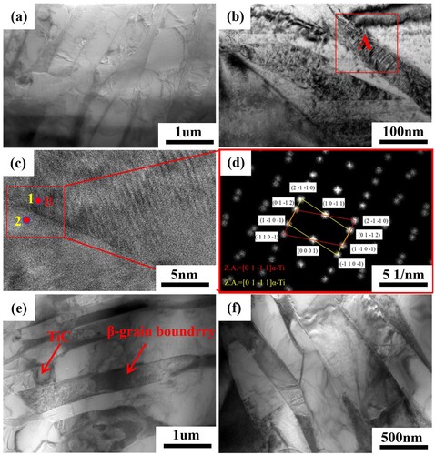
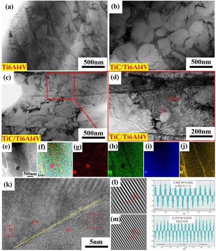
shows the TEM morphology of SLM-formed Ti6Al4 V alloy and TiC/Ti6Al4 V composites before deformation. A small amount of α laths were observed in the Ti6Al4 V alloy matrix under bright field TEM ((a)). The β phase with bcc structure was used as the grain boundary between the α-α laths (called β grain boundary). In addition, twinning behaviour occurred in the matrix after SLM ((b)) inside the acicular α martensite, with the twins crossing the acicular martensite to intersect with the β grain boundary, confirming that the β grain boundary will hinder the growth of twins. The HRTEM images of microtwins in zone A of (b) are shown in (c). Diffraction pattern testing on two points (1 and 2) in area B of (c) revealed an interplanar spacing of 0.2232 nm corresponding to the α-Ti (10-11) crystal plane according to the standard PDF card. This region was Fourier transformed to obtain the twin SAED in (d), showing that the micro twins are coherent twins and {10-11} twins, and {10-11} twins are compressive twins. This is attributed to the rapid cooling during the SLM process causing a large internal stress inside the material to form a stress concentration, thereby promoting the occurrence of twins [Citation29]. The TiC formed in the undeformed sample of the TiC/Ti6Al4 V composite is shown in (e), f. The original TiC is elliptical and measures ∼400 nm due to the rapid cooling of the material during the SLM process hindering the growth of the TiC particles.
Figure 2. Undeformed TEM morphology of the SLM-formed Ti6Al4 V (a-d) and TiC /Ti6Al4 V (e and f) composites.
3.2. Flow stress behaviour
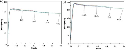
shows the true stress–strain curves of the Ti6Al4 V alloy and TiC/Ti6Al4 V composites under different deformations (15%, 30%, 45% and 60%) and the hot compression condition of 900°C, 1s−1. The true stresses of the Ti6Al4 V alloy and TiC/ Ti6Al4 V composites are 164 ± 10 MPa and 238 ± 10 MPa, respectively, and the ultimate yield strength increased by 47.6%, indicating that TiC ceramic particles improve the mechanical properties of the Ti6Al4 V alloy [Citation30]. This is related to the refinement of martensite size in the composite matrix. Compared with the Ti6Al4 V alloy, the martensite refinement of the TiC/Ti6Al4 V composite increases the number of grain boundaries with more difficult dislocation movement, thereby improving the ultimate yield strength of the composite. In addition, the change in the true stress–strain curve of the TiC/Ti6Al4 V composites is consistent with that of Ti6Al4 V alloy, which is divided into the work hardening stage and the softening stage. Previous studies have shown that the deformation activation energy Q of the TiC/Ti6Al4 V composite is 547 KJ/mol, which is much higher than that of forged Ti6Al4 V alloy Q = 494 KJ/mol and SLM-formed Ti6Al4 V alloy Q = 503 KJ/mol [Citation31]. The self-diffusion activation energy of pure α-Ti is 150 kJ/mol which is much lower than the deformation activation energy of TiC/Ti6Al4 V composites. This proves that the main flow softening mechanism of the composites is dynamic recrystallisation (DRX) rather than the self-diffusion of dynamic recovery [Citation32].
Figure 3. The true stress-strain curves of the SLM-formed Ti6Al4 V (a) and TiC/Ti6Al4 V (b) composites with different deformations at 900°C and 1s−1 strain rate.
3.3. Deformation microstructure
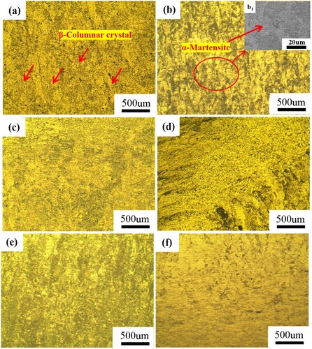
presents the microstructure of SLM Ti6Al4 V and TiC/Ti6Al4 V composites with different deformation at 900°C and 1s−1 strain rate. The microstructure of the Ti6Al4 V alloy before deformation is composed of β columnar crystals parallel to the stress loading direction (construction direction) as shown in (a), whereas the TiC/Ti6Al4 V composite is composed of α martensite ((b)). After compression, the specimen is gradually bent under compressive stress from the original equal axis parallel to the stress loading direction [Citation33]. At 15% compression, the macrostructure of the large deformation zone has obvious fluidity under pressure but when the deformation is 60%, there is no obvious fluidity because the compression is large and the degree of recrystallization is high, so the microstructure is mainly recrystallised grains.
Figure 4. Metallographic structure of the SLM-formed Ti6Al4 V and TiC/Ti6Al4 V composites with different deformation amounts at 900°C and 1s−1 strain rate: (a) undeformed Ti6Al4 V; (b) undeformed TiC/Ti6Al4 V composite; (b1) local magnification of b; (c) 15% Ti6Al4 V deformation; (d) 60% Ti6Al4 V deformation; (e) 15% TiC/Ti6Al4 V deformation; (f) 60% TiC/Ti6Al4 V deformation.
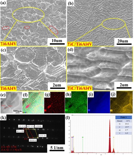
shows the microstructure of the SLM-formed Ti6Al4 V alloy and TiC/Ti6Al4 V composites at 900°C, 1s−1 strain rate and deformation of 15%. The Ti6Al4 V alloy is mainly spherical α structure and acicular α martensite ((a)). As the deformation proceeds, the original acicular α martensite is transformed into a spherical α structure, with some of the acicular martensite in the original structure broken after extrusion and three times the α martensite is formed [Citation34]. Part of the martensite is tilted under stress (as shown in (b)) forming a layered structure. Compared to the Ti6Al4 V alloy, there is no obvious spherical α structure in the composite. The results of EDS point scanning at point 1 in (e) are shown in (l), and the content of C element is 69.41%, confirming that TiC/Ti6Al4 V composites synthesised oval TiC particles with a diameter of ∼400 nm ((e)). TiC particles are embedded in the α lath to hinder the slip of dislocations, thereby enhancing the properties of the TiC/Ti6Al4 V composites. In addition, SAED analysis at the midpoint 2 of (e) revealed a special orientation relationship between the generated TiC particles and the α matrix which is expressed as (−11-1) TiC//(0001) α-Ti, TiC//α-Ti.
Figure 5. Microstructure of the SLM-formed Ti6Al4 V and TiC/Ti6Al4 V composites at 900°C, 1s−1 strain rate and 15% deformation: (a, c) Ti6Al4 V; (b, d) TiC/Ti6Al4 V composites; (e-j) precipitated phase TiC surface scan element distribution map; (k) SAED at point 2; (l) EDS at point 1.
presents the microstructures of the Ti6Al4 V alloy and TiC/Ti6Al4 V composite fabricated by SLM at 900°C, 1s−1 strain rate and 30% reduction. Compared with the microstructure deformed by 15%, the Ti6Al4 V alloy deformed by 30% is dominated by a lath-like α structure with a width of 1–2 μm and a length of 1–10 μm. The distribution of lath α is perpendicular to the deformation direction ((a)). There are spherical α structure and a small amount of α lath in the microstructure of TiC/Ti6Al4 V composites with 30% deformation, after which, there is dislocation pile-up and recrystallisation, increasing the spherical α structure content ((b)), indicating DRX. In addition, the TiC/Ti6Al4 V composite has more recrystallised grains compared to the Ti6Al4 V alloy due to the formation of TiC particles. (c) shows that the diameter of the TiC particles is ∼100 nm and that they are completely inside the α lath. There is a certain amount of dislocation around the TiC particles and a new subgrain boundary is formed on the left side of the TiC particles in the same α lath ((d)). Fast FFT and IFFT on the B region in the α-Ti matrix and the C region of TiC revealed the planar spacing of the lattice fringes in the B and C regions ((k)) are 0.2242 and 0.2275 nm, respectively ((l,m)). The B region corresponds to (10-11) α-Ti, and the C region corresponds to (200) TiC, indicating that the dislocation slip during deformation causes the formed TiC to mismatch the stress/strain on the semi-coherent interface and the mismatch degree formula [Citation35,Citation36] is:
(1)
(1) Where, aγ′ and aγ correspond to the interplanar spacing of γ′ and γ phases, respectively. The mismatch degree of TiC phase and α-Ti matrix at (200) TiC – (10-11) α-Ti interface is 1.5%. According to the Bramfitt lattice matching theory, the (200) TiC – (10-11) α-Ti interface exhibits a coherent relationship due to δ < 5% [Citation37,Citation38].
Figure 6. Microstructure of the SLM-formed Ti6Al4 V and TiC/Ti6Al4 V composites at 900°C, 1s−1 strain rate and 30% deformation: (a) Ti6Al4 V; (b-e) TiC/Ti6Al4 V composites; (f-j) precipitated phase TiC surface scan element distribution map; (k-m) HRTEM images of TiC/Ti6Al4 V composites.
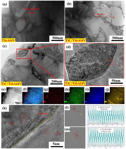
shows the microstructure of the SLM-formed Ti6Al4 V and TiC/Ti6Al4 V composites at 900°C, 1s−1 strain rate and 45% deformation with more obvious recrystallised grains, confirming that the DRX rate of the composites is higher than that of Ti6Al4 V alloy. The reason for this gap is related to more TiC particles produced in situ with a diameter of ∼200 nm ((e) elliptical TiC particles). (e) shows that the contrast on both sides of the TiC particles is different, indicating a different microstructure orientation on both sides of the TiC particles. There is V element aggregation in the α lath which may form the β grain boundary ((e–j)). In addition, the HRTEM results of the selected area in (d) are shown in (k–m). The Fast FFT and IFFT results of the B region in the α-Ti matrix and the C region of the TiC particles in (l,m) show that region B corresponds to (200) TiC and region C corresponds to (1011) α∼Ti. The misfit δ of (200) TiC-(10-11)α-Ti two crystal planes after stress δ is 5.8%. According to Bramfitt's lattice matching theory, TiC particles hinder dislocation movement, resulting in a semi-coherent relationship between crystal planes reducing the stability between TiC particles and the matrix.
Figure 7. Microstructure of the SLM-formed Ti6Al4 V and TiC/Ti6Al4 V composites at 900°C, 1s−1 strain rate and 45% deformation: (a) Ti6Al4 V; (b-e) TiC/Ti6Al4 V composites; (f-j) precipitated phase TiC surface scan element distribution map; (k-m) HRTEM images of TiC/Ti6Al4 V composites.
shows the microstructure of the SLM-formed Ti6Al4 V and TiC/Ti6Al4 V composites at 900°C, 1s−1 strain rate and 60% deformation. Compared with the samples deformed by 30% and 45%, the lath-shaped α structure is reduced, while the spherical α structure and elliptical α structure are increased ((a,b)) because the DRX rate increases with increased deformation and is greater than the rate of dislocation generation after the compression reaches a certain degree. The TiC/Ti6Al4 V composite with 60% deformation contains a large amount of spheroidised α structure inside the α lath ((c)). A large number of nano-scale recrystallised grains with a reduced α lath structure was observed by TEM ((d)), confirming that the DRX rate was accelerated by increasing the deformation. The increased DRX rate refined the formed lath structure into nanoscale recrystallised grains.
Figure 8. Microstructure of the SLM-formed Ti6Al4 V and TiC/Ti6Al4 V composites at 900°C, 1s−1 strain rate and 60% deformation: (a-b) Ti6Al4 V; (e-f) TiC/Ti6Al4 V composites; (g-l) precipitated phase TiC surface scan element distribution map.
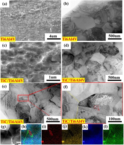
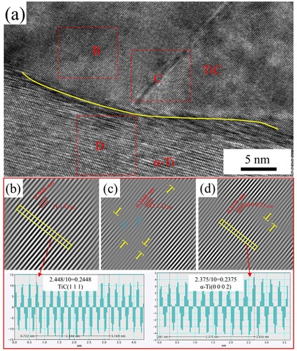
The effect of TiC on DRX was analysed by observing the morphology and microstructure of TiC particles in the 60% deformed sample ((e–l)) showing microstructures with different orientations and contrasts. Combined with the V element distribution in (l), there are α and β phases with different orientations around the formed TiC with a new subgrain boundary at the tip of the formed TiC particles ((f)). (e) shows that a new subgrain boundary segmentation α structure is formed during deformation. In addition, several dislocations are crossing the TiC particles ((f)). The HRTEM of (f) is shown in and Fast FFT and IFFT on the B and C regions of the TiC particles selected in (a) and the D region in the α-Ti matrix show that the plane spacing of each lattice fringe in the B and D regions 0.2448 and 0.2375 nm, respectively ((b,d)). Region B corresponds to the (111) TiC crystal plane and region D corresponds to the (0002) α-Ti crystal plane. There are some edge dislocations in the α-Ti matrix ((d)) but no dislocations in the B region. However, the inverse Fourier transform of the C region shows that the dislocations across the TiC particles are composed of edge dislocations and screw dislocations, suggesting that TiC particles will also deform after the deformation reaches a certain degree, resulting in dislocation and slip. The mismatch degree δ of the (111) TiC – (0002) α-Ti crystal plane after stress is 3.0%, therefore, there is a coherent relationship between the TiC-(0002)α-Ti interfaces, thereby promoting a strong interfacial bonding between the second phase particles and the Ti matrix [Citation39].
Figure 9. HRTEM images of TiC/Ti6Al4 V composites with 60% compression.
4. Discussion
4.1. Dislocation mechanism
The geometrically necessary dislocation (GND) was studied by comparing the local misorientation (KAM) under various deformation conditions. The driving force of DRX increases with the increase of GNDs [Citation40,Citation41], which can be expressed as follows [Citation42,Citation43]:
(2)
(2) Where μ is the step length = 1.2 μm and b is the length of Burgers vector = 0.289 nm, representing the average KAM value of the selected region which can be calculated using the following formula [Citation44]:
(3)
(3)
Where represents the local offset at point i, represents the local offset at adjacent point j.
The KAM image defined by EBSD gradually increases from blue to green [Citation45], with the smallest dislocation density located in the blue area and the highest dislocation density in the red area in of the SLM-formed Ti6Al4 V alloy and TiC/Ti6Al4 V composites with different deformation at 900°C and 1s−1 strain rate. The dislocation density of the Ti6Al4 V alloy ((a–f)) and TiC/Ti6Al4 V composites ((g–l)) increased, then decreased with increasing deformation [Citation46]. The significant decrease in the blue area indicates a significant increase in dislocations from the undeformed sample to the sample with a compression rate of 15%. When the compression reaches 30%, the KAM image is mainly green with a small amount of blue areas, whereas the image is almost all green when the deformation is 45% indicating the largest KAM value and geometric dislocation density. When the deformation is 60%, the green area is reduced indicating significantly reduced dislocation in the sample because the formation and growth rate of recrystallisation is greater than the dynamic recovery rate, thereby consuming a large number of dislocations and reducing the necessary geometric dislocation density.
Figure 10. KAM diagram of the SLM-formed Ti6Al4 V (a-f) and TiC/Ti6Al4 V (g-l) composites with different deformations at 900°C and 1 s−1 strain rate.
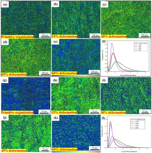
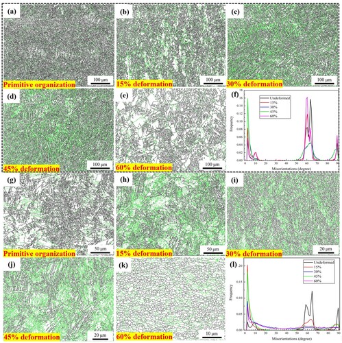
The grain boundary is divided into small angle grain boundary and large angle grain boundary according to the size of the orientation difference between adjacent grains. the grain boundary is divided into small angle grain boundary and large angle grain boundary. The small angle orientation difference is less than 15° and the dislocation density can be qualitatively judged using the small angle grain boundary [Citation47]. is the grain boundary diagram of the SLM-formed Ti6Al4 V alloy and TiC/ Ti6Al4 V composite at different deformation angles at 900°C and 1 s−1 strain rate, with green indicating the small angle grain boundary and black is the large angle grain boundary. The low-angle grain boundaries of Ti6Al4 V alloy and composites increase, then decrease in line with the KAM results. There are more low-angle grain boundaries at 45% deformation with a geometric dislocation density of 2.58 × 10¹⁹ m−2, which is 1.7 times that of the Ti6Al4C alloy. This is due to the initial work hardening of the sample resulting in lattice distortion and increased dislocation density. In addition, the low-angle grain boundaries were mainly distributed inside the α structure, indicating that dislocations slip and form dislocation tangles inside the grains.
Figure 11. Grain boundary diagram of the SLM-formed Ti6Al4 V (a-f) and TiC/Ti6Al4 V composites (g-l) with different deformation at 900°C and 1s−1 strain rate.
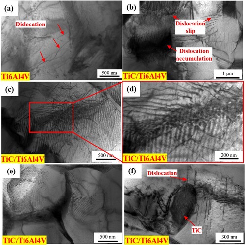
is the TEM dislocation morphology of the Ti6Al4 V alloy and TiC/Ti6Al4 V composite showing that the number of dislocations in the α structure of TiC/ Ti6Al4 V composites before deformation is significantly higher than that in the Ti6Al4 V alloy ((a,b)). When thermal deformation occurs, the dislocation slip makes the β grain boundaries of the α lath intersect, thereby hindering the dislocation slip. The dislocation pile-up formed inside the α structure intersects with the β grain boundary to form a dislocation pile-up across the α lath ((c,d)), resulting in recrystallisation ((e)). In addition, the generated TiC particles in the composites are distributed inside the α lath (). It is speculated that the dislocations cannot cut through TiC particles and can only be bypassed under stress ((f)).
Figure 12. Dislocation morphology of the Ti6Al4 V alloy and TiC/Ti6Al4 V composite: (a) undeformed Ti6Al4 V alloy; (b) undeformed TiC/Ti6Al4 V composites; (c, d, e, f) 15% TiC/Ti6Al4 V composites.
4.2. Slip system and texture
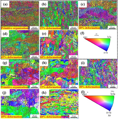
shows the grain orientation diagram and IPF diagram of the SLM-formed Ti6Al4 V and TiC/Ti6Al4 V composites at 900°C and 1s−1 strain rate. The undeformed IPF diagram of Ti6Al4 V alloy mainly has orange and purple structures ((a)), in which the fine green structure is α martensite and the texture strength is 7.59 ((a,l)). The TiC/Ti6Al4 V composites mainly have green and purple structures ((g)) with a maximum texture strength of 10.24 ((a2)). This indicates that there is more grain orientation in the SLM-formed samples to generate TiC nanoparticles to improve the texture strength of the composites. In addition, the IPF map in the X0 direction < −12-10 > corresponds to the IPF map in the Z0 direction < 0001>, resulting in a basal fibre texture with a grain orientation of compression//<−12-10 >. Compression deformation causes a change in grain orientation, evolving from the c-axis parallel to the XOY plane in the undeformed sample to the basal fibre texture perpendicular to the XOY plane along the c-axis. When the composite material deforms by 30%, grain refinement occurs and the texture strength decreases to 3.83 because recrystallisation weakens the texture strength. The texture strength is smaller and the grain distribution is more uniform compared with Ti6Al4 V alloy, possibly due to the generation of nanoscale TiC particles promoting the recrystallisation of the composite material.
Figure 13. Grain orientation maps and IPF maps of the Ti6Al4 V (a-f) and TiC/Ti6Al4 V composites (g-l) formed by SLM under different deformation amounts at 900°C and 1s−1 strain rates.
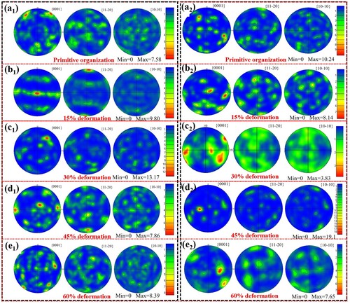
shows the pole diagram of different deformation amounts for the SLM-formed Ti6Al4 V and TiC/Ti6Al4 V composite materials at 900°C and 1s−1 strain rate. There are two texture concentrations in the outer ring of {0001} plane before the deformation of the Ti6Al4 V alloy with a texture intensity of 7.58. The maximum texture intensity is 13.17 when the deformation is 30% ((b1–e1)) and the texture intensity increases and then decreases with increased deformation because DRX occurs changing the grain orientation inside the sample, mainly into orientation ((f)). When the deformation is 45%, the texture strength increases to 19.1, which is greatly increased compared with Ti6Al4 V alloy. At this time, the acicular crystal in the crystal is the matrix surrounded by the structure formed by the growth and fusion of twins, so the grain size is larger than that at 30% compression. In the {0001} plane pole figure, the basal texture on the X0 axis has almost no component, indicating that the matrix of the basal texture changes to other orientations as the twin evolves.
Figure 14. Extreme diagram of different deformation amounts of the SLM-formed Ti6Al4 V (a1-e1) and TiC/Ti6Al4 V composites (a2-e2) materials at 900°C and 1s−1 strain rate.
is the Smith diagram of different deformation of the SLM-formed Ti6Al4 V and TiC/Ti6Al4 V composites at 900°C and 1s−1 strain rate. The plastic deformation of metals is closely related to the Schmid factor (SF) which changes from blue to red indicating hard orientation to soft orientation. Red (soft orientation) indicates that the grain is prone to slip whereas blue (hard orientation) indicates that it is difficult to slip [Citation48,Citation49]. The pole figure shows that the Ti6Al4 V alloy and composite materials mainly form a basal texture during hot deformation, and the texture intensity increases and then decreases with increased deformation. Therefore, by studying the SF of the basal slip system <a>{0001}<11-20>, the softening mechanism can be further explained. The change of SF is related to the rotation of the crystal structure and the recrystallisation during the deformation. Comparing the change in the base slip system SF of the two materials revealed that the change in SF is related to the rotation and recrystallisation of the crystal structure. The proportion of their soft orientation SF decreases at 15% compression, increases at 30% compression and decreases when the compression reaches 45%. When the compression reaches 60%, the TiC/Ti6Al4 V composite continues to decrease, while the Ti6Al4 V alloy increases. The SF ratio of the soft orientation of both materials increases when the compression is 30%, possibly due to the internal stress of the sample increasing under the action of external stress with the compression. The grain orientation is rotated by internal stress and the heat provided causes the atoms in the sample to rotate the grain orientation, thereby increasing the proportion of the SF soft orientation.
Figure 15. Smith plots of different deformation amounts of the SLM-formed Ti6Al4 V (a-f) and TiC/Ti6Al4 V composites (g-l) at 900°C and 1s−1 strain rate.
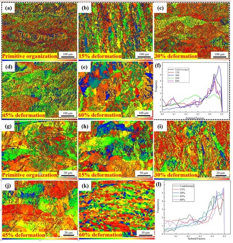
and show the SF statistics of the Ti6Al4 V alloy and TiC/Ti6Al4 V composite material, respectively. When the composite material is not deformed, the soft-oriented SF accounts for 36.4%, which is reduced by 10% compared to the Ti6Al4 V alloy. The generation of TiC particles can reduce the SF of the grain soft orientation, as shown in the colour distribution in the Smith plot in . When the composite material is compressed to 15%, the proportion of the soft-oriented SF is 35%, which is reduced by 1.4% compared to the undeformed composite material and 1.3% compared to the Ti6Al4 V alloy. shows that the blue area in the composite material with 15% deformation is larger than in the undeformed sample and the distribution of the hard-oriented SF is more uniform compared to the Ti6Al4 V alloy. Also, the proportion of the soft-oriented SF in the composite material at 30% compression is reduced. Comparing the Smith soft orientation factor ratios of the Ti6Al4 V alloy and TiC/Ti6Al4 V composite materials at 30% to 45% deformation reveals that the composite materials were almost the same, while the Ti6Al4 V alloy showed a significant decrease. The grain orientation transformation rate in composite materials is faster than that in the Ti6Al4 V alloy. When the deformation is 60%, the soft orientation SF of the composite material is still decreasing and the slip rate of dislocations within the grains is still higher than the rate of grain orientation rotation to soft orientation, which is opposite to the Ti6Al4 V alloy.
Table 2. SF factor statistics of the Ti6Al4 V alloy with different deformations.
Table 3. SF factor statistics of the TiC/Ti6Al4 V composites with different deformations.
4.3. TiC strengthening mechanism
The Ti6Al4 V alloy formed by SLM has a basket-shaped α martensite microstructure ((a)). After deformation, some needle-like martensite forms spherical shapes under external forces and as the amount of compression increases, the fluidity of the organisation increases initially forming α spherical tissue and needle-like martensite equiaxed structures α organisation. When the compression reaches 60%, the martensite disappears and the microstructure is mainly recrystallised grains due to DRX. By combining the grain boundary diagrams of different sizes and angles with KAM diagrams, it can be concluded that dislocations are usually located in α accumulation and entanglement occurs forming small angle grain boundaries. As the deformation progresses, there are two dislocation stacking mechanisms in the flat noodles: one spanning across α dislocation in flat noodles and β grain boundaries intersect each other. The accumulation of dislocations can hinder the subsequent movement of dislocations, leading to the formation of subgrain boundaries and new grain boundaries, with recrystallisation occurring through the nucleation of grain boundary arches ((c)).
Figure 16. The effect and strengthening mechanism of TiC on dislocations: (a) net-basket acicular martensite; (b) evolution of the deformed structure; (c) schematic diagram of the dislocation increment principle of the Ti6Al4 V alloy; (d) effect of TiC on the dislocation and strengthening mechanism.
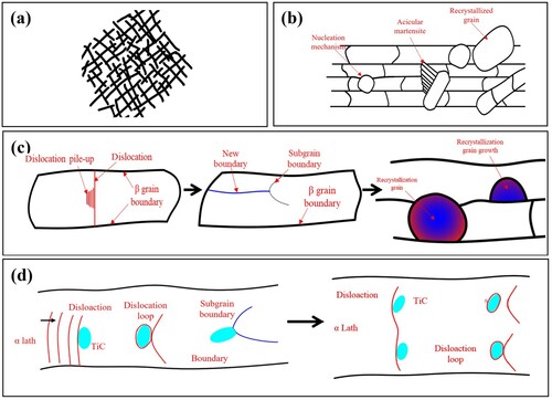
The TiC particles generated in situ during SLM are distributed inside the α lath martensite and during deformation, the acicular martensite is transformed into α lath martensite and the TiC particles cause an Orowan strengthening effect on the dislocation slip [Citation50]. Dislocations bypass TiC particles ((f)) and the mechanism is shown in (d). There is a long dislocation inside the α lath which intersects with the TiC particles as well as the grain boundary formed by the β phase to hinder dislocation slip. TiC particles hinder dislocation slip, leading to dislocation accumulation, and forming subgrain boundaries. As the deformation increases, there is a trend of grain boundary migration in TiC particles. In addition, the TiC particles in the α lath pin the dislocation forming the Frank-Reed source proliferation mechanism, significantly increasing the dislocation density. Increased deformation accelerates the refinement of the lath α structure and the formation and growth of recrystallised grains, therefore, the dislocation density in the TiC/Ti6Al4 V composite is higher than that in the Ti6Al4 V alloy.
The main strengthening mechanism of the TiC/Ti6Al4 V composites is the generation of TiC particles and the grain refinement effect. It is possible to determine which of the two reinforcement mechanisms is dominant through model calculations.
The strengthening of TiC particle dislocations mainly involves Orowan strengthening caused by thermal expansion mismatch between the matrix alloy and precipitates, as well as strengthening caused by the strain gradient effect. Ramakrishnan proposed an analytical model to predict the yield strength by combining the modified shear lag model and the enhanced dislocation density model of particle-reinforced composites [Citation51]:
(4)
The general expression for f1 is [Citation52,Citation53]:
(6)
(6) Fd is given by the following equation:
(7)
(7)
(8)
(8) Where Δσ Dis is the increase in yield strength caused by dislocation strengthening, middle Δσ Or is the Orowan stress or increase in stress required to allow dislocations to pass through the obstructed precipitation phase array, Δσ is the stress increment is caused by the thermal expansion mismatch between the matrix alloy and the precipitated phase, ΔσGND is the stress contribution caused by the strain gradient effect. The strain gradient effect is related to the geometrically necessary dislocation distribution required to adapt to the plastic deformation mismatch between the matrix and reinforcement. The Orowan stress can be described by the Orowan Ashby equation [Citation54]:
(9)
(9)
Where Gm and b are the shear modulus and Burgers vector of the metal matrix, respectively and Gm = 24.7 Gpa, b = 0.289 nm, and r is the particle radius, λ The spacing between particles is represented as:
(10)
(10) Where dp is the diameter of the particle, and VTiC is the volume fraction of TiC. The stress increment caused by thermal expansion mismatch can be expressed as [Citation55]:
(11)
(11)
Where k is a constant approximately equal to 1.25 and ρ is an enhanced dislocation density given by the following equation:
(12)
(12) Where Δα is the difference between the thermal expansion coefficients of the matrix and the reinforcing particles, Δα = 3.3 × 10⁻⁶K−1[Citation55]; Δ T is the temperature change from processing temperature to testing temperature; B is the Burgers vector of the metal matrix. The stress increment caused by geometrically necessary dislocations [Citation56]:
(13)
(13)
Where ξ is a geometric factor with a value of 0.4, ϵ is the plastic strain of the metal matrix. In the calculation of yield strength, a value of 0.002 is used but due to the small plastic strain (0.002), Δσgnd was not taken into account in this work. The TiC/Ti6Al4 V composite material ΔσTiC was calculated to be 30 MPa, accounting for 38.5% of the total improvement.
| (2) | TiC particles generated during the SLM formation of TiC/Ti6Al4 V composites refine the size of needle-like martensite. The finer the grain size, the more grain boundaries there are, thereby improving the strength of TiC/Ti6Al4 V composites and their contribution is represented by the Hall Petch [Citation57] equation:
| ||||
5. Conclusions
Ti6Al4 V alloy and TiC/Ti6Al4 V composites were fabricated by SLM to evaluate the microstructure evolution and strengthening mechanism of hot deformation at 900°C, 1s−1 rate and different deformation were studied. The main findings are summarised as follows:
The yield strength of the TiC/Ti6Al4 V composite is 78 MPa higher than that of the Ti6Al4 V alloy. The softening process of TiC/Ti6Al4 V composite material is also a DRX process and the basal texture during compression is smaller than that of the Ti6Al4 V alloy.
The geometric dislocation density of TiC/Ti6Al4 V composites increases and then decreases during compression from 0 to 60%. The interface relationship between the (200) TiC crystal plane and (10-11) α-Ti crystal plane between TiC particles and Ti matrix changes from a coherent interface to a semi-coherent interface during deformation.
During the compression of TiC/Ti6Al4 V composites, the dislocation slips inside the lath α. The accumulation of dislocations around TiC particles forms dislocation cells and accelerates the recrystallisation process by forming subgrain boundaries.
The ultimate yield strength of TiC/Ti6Al4 V composites is mainly caused by grain refinement, supplemented by Orowan strengthening produced by the TiC particles.
CRediT authorship contribution statement
Zhanyong Zhao: Visualization. Jianbin Wang: Writing-review & editing, Conceptualization, Methodology, Software. Wenbo Du: Data curation, Writing-original draft. Peikang Bai: Supervision. Liqing Wang: Supervision. Zhen Zhang: Investigation. Zhiquan Huang: Investigation.
Declaration of competing interest
The authors declare that they have no known competing financial interests or personal relationships that could have appeared to influence the work reported in this paper.
Acknowledgements
This work was supported by the National Natural Science Foundation of China (Grant No. 52275389, 52075357) and Scientific and Technologial Innovation Programs of Higher Education Institutions in Shanxi (2020L0316, 2019L0608).
Disclosure statement
No potential conflict of interest was reported by the author(s).
Additional information
Funding
References
- Brewer WD, Bird RK, Wallace TA. Titanium alloys and processing for high speed aircraft. Mater Sci Eng A, 1998;243(1): 299-304.doi:10.1016/S0921-5093(97)00818-6
- Boyer RR. An overview on the use of titanium in the aerospace industry. Mater Sci Eng A, 1996;213(1): 103-114. doi:10.1016/0921-5093(96)10233-1
- Banerjee D, Williams JC. Perspectives on Titanium Science and Technology [J]. Acta Mater. 2013;61(3):844–879. doi:10.1016/j.actamat.2012.10.043
- Li J, Cai J, Zhou M, et al. High Cycle Fatigue Properties and Fracture Behavior of TC4 Titanium Alloy at Room and Elevated Temperatures [J]. 2023;972: 278-286.doi:10.1007/978-981-19-7652-0_26
- Armstrong M, Mehrabi H, Naveed N. An overview of modern metal additive manufacturing technology. J Manuf Processes. 2022;84:1001–1029. doi:10.1016/j.jmapro.2022.10.060
- Xie Z, Dai Y, Ou X, et al. Effects of selective laser melting build orientations on the microstructure and tensile performance of Ti–6Al–4V alloy. Mater Sci Eng A. 2020;776:139001. doi:10.1016/j.msea.2020.139001
- Liović D, Franulović M, Kozak D. Material models and mechanical properties of titanium alloys produced by selective laser melting. Procedia Struct Integr. 2021;31:86–91. doi:10.1016/j.prostr.2021.03.014
- Ghodrati H, Ghomashchi R. Effect of graphene dispersion and interfacial bonding on the mechanical properties of metal matrix composites: An overview. FlatChem. 2019;16:100113. doi:10.1016/j.flatc.2019.100113
- Jiao Y, Huang L, Geng L. Progress on discontinuously reinforced titanium matrix composites, J Alloys Compd, 2018, 767: 1196-1215.doi:10.1016/j.jallcom.2018.07.100
- Poletti C, Balog M, Schubert T, et al. Production of titanium matrix composites reinforced with SiC particles. Compos Sci Technol. 2008;68(9):2171–2177. doi:10.1016/j.compscitech.2008.03.018
- Kim YJ, Chung H, Kang SJ. Processing and mechanical properties of Ti–6Al–4V/TiC in situ composite fabricated by gas–solid reaction. Mater Sci Eng A, 2002;333(1): 343-350. doi:10.1016/S0921-5093(01)01858-5
- Huang LJ, Yang FY, Hu HT, et al. TiB whiskers reinforced high temperature titanium Ti60 alloy composites with novel network microstructure. Mater Des 2013;51:421–426. doi:10.1016/j.matdes.2013.04.048
- Kondoh K, Threrujirapapong T, Imai H, et al. Characteristics of powder metallurgy pure titanium matrix composite reinforced with multi-wall carbon nanotubes. Compos Sci Technol. 2009;69(7):1077–1081. doi:10.1016/j.compscitech.2009.01.026
- Even C, Arvieu C, Quenisset JM. Powder route processing of carbon fibres reinforced titanium matrix composites. Compos Sci Technol, 2008;68(6): 1273-1281.doi:10.1016/j.compscitech.2007.12.014
- Luo X, Ji X, Yang Y, et al. Microstructure evolution of C/Mo double-coated SiC fiber reinforced Ti6Al4V composites. Mater Sci Eng A, 2014, 597: 95-101.doi:10.1016/j.msea.2013.12.077
- Hayat MD, Singh H, He Z, et al. Titanium metal matrix composites: An overview. Composites Part A. 2019;121:418–438. doi:10.1016/j.compositesa.2019.04.005
- Zhou Z, Liu Y, Liu X, et al. Microstructure evolution and mechanical properties of in-situ Ti6Al4V–TiB composites manufactured by selective laser melting. Composites Part B. 2021;207:108567. doi:10.1016/j.compositesb.2020.108567
- Gu D, Wang Z, Shen Y, et al. In-situ TiC particle reinforced Ti–Al matrix composites: Powder preparation by mechanical alloying and Selective Laser Melting behavior. Appl Surf Sci 2009;255(22):9230–9240. doi:10.1016/j.apsusc.2009.07.008
- Ming W, Chen J, An Q, et al. Dynamic mechanical properties and machinability characteristics of selective laser melted and forged Ti6Al4V. J Mater Process Technol. 2019; 271: 284-292.doi:10.1016/j.jmatprotec.2019.04.015
- Li PH, Guo WG, Huang WD, et al. Thermomechanical response of 3D laser-deposited Ti–6Al–4V alloy over a wide range of strain rates and temperatures. Mater Sci Eng A. 2015;647:34–42. doi:10.1016/j.msea.2015.08.043
- Song J, Han Y, Fang M, et al. Temperature sensitivity of mechanical properties and microstructure during moderate temperature deformation of selective laser melted Ti-6Al-4V alloy. Mater Charact 2020;165:110342. doi:10.1016/j.matchar.2020.110342
- He Y, Ma YE, Zhang W, et al. Effects of build direction on thermal exposure and creep performance of SLM Ti6Al4V titanium alloy. Eng Fail Anal. 2022;135: 106063.doi:10.1016/j.engfailanal.2022.106063
- Kim YK, Park SH, Yu JH, et al. Improvement in the high-temperature creep properties via heat treatment of Ti-6Al-4V alloy manufactured by selective laser melting. Mater Sci Eng A. 2018;715:33–40. doi:10.1016/j.msea.2017.12.085
- Cheng Q, Zhang P, Ma X, et al. Microstructure evolution and wear mechanism of in situ prepared Ti–TiN cermet layers at high temperature. Compos Part B. 2022;242:110028. doi:10.1016/j.compositesb.2022.110028
- Pan J, Yang J, Zhang W, et al. High-temperature deformation behavior and microstructure evolution of TiBw/Ti6Al4V composites during hot shear-compression deformation. J Mater Res and Technol. 2021;15:1155–1164. doi:10.1016/j.jmrt.2021.08.089
- Tang MK, Zhang L.C, Zhang N, Microstructural evolution, mechanical and tribological properties of TiC/Ti6Al4 V composites with unique microstructure prepared by SLM. Mater Sci Eng, A. 2021, 141187(814),doi:10.1016/j.msea.2021.141187
- Jiang Q.H, Li S, Sai Guo, et al. Comparative study on process-structure-property relationships of TiC/Ti6Al4 V and Ti6Al4 V by selective laser melting[J]. Int J Mech Sci. 2023, 107963(241),doi:10.1016/j.ijmecsci.2022.107963
- Li C, Li W, Lashari MI, et al., Life prediction and failure analysis in laser powder bed fused TiC/Ti6Al4 V titanium matrix composite under high cycle and very high cycle fatigue conditions. Int J Fatigue, 2024, 108101(180), doi:10.1016/j.ijfatigue.2023.108101
- Luque A, Ghazisaeidi M, Curtin WA. A new mechanism for twin growth in Mg alloys. Acta Mater 2014;81:442–456. doi:10.1016/j.actamat.2014.08.052
- Chang, S.J., Microstructure and High Temperature-Mechanical Properties of TiC/Graphene/Ti6Al4V Composite Formed by Laser Powder Bed Fusion. Metals (Basel) 13: 163. doi:10.3390/met13010163
- Motoyama Y, Tokunaga H, Kajino S, et al. Stress–strain behavior of a selective laser melted Ti-6Al-4V at strain rates of 0.001–1/s and temperatures 20–1000 °C. J Mater Process Technol. 2021;294:117141. doi:10.1016/j.jmatprotec.2021.117141
- Lee WS, Lin CF. High-temperature deformation behaviour of Ti6Al4 V alloy evaluated by high strain-rate compression tests [J]. J Mater Process Technol. 1998;75(1): 127-136. doi:10.1016/S0924-0136(97)00302-6
- Mutombo K, Siyasiya C, Stumpf WE. Diffusional transformation in Ti6Al4 V alloy during isothermal compression. Trans. Nonferrous Met Soc China, 2019, 29(10): 2078-2089. doi:10.1016/S1003-6326(19)65114-9
- Villa M, Pantleon K, Reich M, et al. Kinetics of anomalous multi-step formation of lath martensite in steel. Acta Mater 2014;80:468–477. doi:10.1016/j.actamat.2014.08.031
- Guan RG, Shen YF, Zhao ZY, et al. Nanoscale precipitates strengthened lanthanum-bearing Mg-3Sn-1Mn alloys through continuous rheo-rolling. Sci Rep. 2016;6:23154. doi:10.1038/srep23154
- Diologent F, Caron P, Almeida T, et al. The γ/γ′ mismatch in Ni based superalloys: In situ measurements during a creep test. Nucl Instrum Methods Phys Res, Sect B, 2003;200: 346-351. doi:10.1016/S0168-583X(02)01699-3
- Housaer F, Beclin F, Touzin M, et al. Interfacial characterization in carbon nanotube reinforced aluminum matrix composites. Mater Charact 2015;110:94–101. doi:10.1016/j.matchar.2015.10.014
- Chu K, Wang F, Wang X-h, et al. Interface design of graphene/copper composites by matrix alloying with titanium. Mater Des, 2018, 144: 290-303. doi:10.1016/j.matdes.2018.02.038
- Zhao Z, Wang S, Du W, et al. Interfacial structures and strengthening mechanisms of in situ synthesized TiC reinforced Ti6Al4V composites by selective laser melting. Ceram Int 2021;47(24):34127–34136. doi:10.1016/j.ceramint.2021.08.323
- Zhao L Y, Yan H, Chen RS, et al. Orientations of nuclei during static recrystallization in a cold-rolled Mg-Zn-Gd alloy. Mater Sci Technol, 2021, 60: 162-167. doi:10.1016/j.jmst.2020.05.027
- Lee JH, Lee JU, Kim S-H, et al. Dynamic recrystallization behavior and microstructural evolution of Mg alloy AZ31 through high-speed rolling. J Mater Sci Technol. 2018;34(10):1747–1755. doi:10.1016/j.jmst.2018.03.002
- Kubin LP, Mortensen A. Geometrically necessary dislocations and strain-gradient plasticity: a few critical issues. Scr Mater. 2003;48(2):119–125. doi:10.1016/S1359-6462(02)00335-4
- Gao H, Huang Y, Nix WD, et al. Mechanism-based strain gradient plasticity— I. Theory. J Mech Phys Solids, 1999;47(6): 1239-1263. doi:10.1016/S0022-5096(98)00103-3
- Yan Z, Wang D, He X, et al. Deformation behaviors and cyclic strength assessment of AZ31B magnesium alloy based on steady ratcheting effect Mater Sci Eng, A. 2018;723:212–220. doi:10.1016/j.msea.2018.03.023
- Wang JB, Zhao ZY, Du WB, et al., Uniaxial compression deformation and fracture mechanism of cold metal transfer (CMT) arc additive Mg–Gd–Y–Zn–Zr alloy, Mater Sci Eng A, 2023;878:145201,doi:10.1016/j.msea.2023.145201
- Ma Q, Wei K, Xu Y, et al. Exploration of the static softening behavior and dislocation density evolution of TA15 titanium alloy during double-pass hot compression deformation [J]. J Mater Res and Technol, 2022;18: 872-881.doi:10.1016/j.jmrt.2022.02.122
- Marion C, Dirk P, Eralp D, et al. Orientation gradients and geometrically necessary dislocations in ultrafine grained dual-phase steels studied by 2D and 3D EBSD. Sci Eng. 2010;527:2738–2746. doi:10.1016/j.msea.2010.01.004
- Zhang Z, Fan J, Tang B, et al. Microstructural evolution and FCC twinning behavior during hot deformation of high temperature titanium alloy Ti65. J Mater Sci Technol. 2020;49:56–69. doi:10.1016/j.jmst.2020.02.026
- Zhao PK, Wei C, Xiao XD, et al. Thermal deformation mechanism of TC11/TC17 linear friction welded joint during isothermal compression. Mater Charact. 2021;178:111319. doi:10.1016/j.matchar.2021.111319
- Chen L, Sun Y, Li L, et al. Microstructure evolution, mechanical properties, and strengthening mechanism of TiC reinforced Inconel 625 nanocomposites fabricated by selective laser melting. Sci Eng A. 2020;792:139655. doi:10.1016/j.msea.2020.139655
- Ramakrishnan N. An analytical study on strengthening of particulate reinforced metal matrix composites. Acta Mater, 1996;44(1): 69-77. doi:10.1016/1359-6454(95)00150-9
- Nardone VC, Prewo KM. On the strength of discontinuous silicon carbide reinforced aluminum composites. Scr Metall. 1986;20(1): 43-48. doi:10.1016/0036-9748(86)90210-3
- Zhang Q, Chen DL. A model for predicting the particle size dependence of the low cycle fatigue life in discontinuously reinforced MMCs. Scr Metall. 2004;51(9):863–867. doi:10.1016/j.scriptamat.2004.07.006
- Taya M, Arsenault RJ. Metal matrix composites: thermomechanical behavior. F. 1989 [C].
- Ma F, Wang T, Liu P, et al. Mechanical properties and strengthening effects of in situ (TiB+TiC)/Ti-1100 composite at elevated temperatures. Mater Sci Eng, A. 2016;654:352–358. doi:10.1016/j.msea.2015.12.071
- Brown LM, Stobbs WM. The work-hardening of copper-silica v. equilibrium plastic relaxation by secondary dislocations. Philos Mag: A J Theoretical Experimen Appl Phys. 1976;34(3):351–372. doi:10.1080/14786437608222028
- Hill D, Banerjee R, Huber D, et al. Formation of equiaxed alpha in TiB reinforced Ti alloy composites. Scr Mater. 2005;52(5):387–392. doi:10.1016/j.scriptamat.2004.10.019
- Sun S, Wang M, Wang L, et al. The influences of trace TiB and TiC on microstructure refinement and mechanical properties of in situ synthesized Ti matrix composite. Composites Part B. 2012;43(8):3334–3337. doi:10.1016/j.compositesb.2012.01.075