
ABSTRACT
The wire arc additive manufacturing (WAAM) process often begins printing on a substrate. In some cases, the substrate could act as a functional part of the WAAM-fabricated parts. In this work, ER70S-6 is directly deposited onto a 316L substrate using the WAAM process. Microstructural studies reveal good fusion and bonding at the interface. Due to the dilution of ER70S-6 and 316L, a gradient change in composition and microstructure was observed in the first six layers. The first layer (Fe-10Cr-5.5Ni-1Mo-1Mn) and the second layer (Fe-4Cr-2Ni-1Mn-0.5Mo) exhibit a bainite microstructure. Ferritic grains were observed from the third layer onwards. The microhardness is high at 336.9 ± 6.3 HV for the first layer and 302.7 ± 5.7 HV for the second layer. A decrease in microhardness was observed with the increase of the building layer until layer six. The yield strength is 356.6 MPa and the UTS is 502.3 MPa for the 316L/ER70S-6 bimetal joint. The digital image correlation (DIC) method is used to analyse the deformation behaviour. During the tensile test, the 316L substrate side yields first, and then the deformation shifts to the ER70S-6 side. This study also holds the potential for the development of novel alloys.
1. Introduction
Additive manufacturing (AM) has revolutionised production design and fabrication by enabling the direct fabrication of components from a 3D CAD model through a layer-by-layer building approach. It has been proven to be efficient in accelerating product development, enhancing product quality and reducing energy consumption.
Fusion-based metal AM is the most popular AM process which includes laser powder bed fusion (LPBF) [Citation1], electron beam powder bed fusion (EBPBF) [Citation2], laser metal deposition (LMD) [Citation3] and WAAM [Citation4] processes. Among them, the WAAM technique, which transformed from the arc welding technique, possesses the highest deposition speed. Therefore, it is advantageous in the fabrication of large-volume components. Wynne et al. [Citation5] collaborated with MX3D (Amsterdam, Netherlands) to fabricate and test the world's first metal additively manufactured bridge which has a length of about 10 m. The bridge is now at OZ Achterburgwal, Amsterdam.
As the WAAM technique advances, the integrity of equipment and process control has become increasingly mature for industrial applications. Therefore, it has attracted tremendous attention in the academic community. Palmeira Belotti et al. [Citation6] studied the effect of printing strategy on the microstructure and mechanical properties of WAAM-fabricated 316L. Three strategies, including layer-wise unidirectional, layer-wise weaving and bidirectional zig-zag scanning paths, are applied. The layer-wise unidirectional and weaving strategies demonstrate a notable orientation dependency in ductility. Conversely, the bidirectional zig-zag sample shows significantly reduced orientation dependence in mechanical behaviour. Wang et al. [Citation7] studied the influence of arc mode on the microstructure and mechanical properties of 316L using the WAAM process. Two arc modes, including SpeedArc and SpeedPulse provided by Lorch power source, are compared in their study. They revealed that the SpeedArc mode has a lower heat input and a higher cooling rate. The tensile strengths and hardness values of the components produced by SpeedArc WAAM are higher than those of components produced by SpeedPulse. Other materials that have been frequently studied using the WAAM process are Al alloys [Citation8,Citation9], Inconel alloys [Citation10], Ti-6Al-4V alloys [Citation11], precipitation hardening martensitic stainless steels [Citation12,Citation13], etc.
Currently, the majority of research has concentrated on investigating the microstructure and mechanical characteristics of WAAM-produced materials. However, the literature frequently neglects to address the joining properties between the substrate and the WAAM-built materials. In certain scenarios, the substrate may serve a functional role within the component. Additionally, the mechanical properties become crucial particularly when stress is applied at the interface. Consequently, it is imperative to thoroughly examine and evaluate the bonding quality at the interface between the substrate and the WAAM-built material.
Multimaterial structures and functionally graded materials (FGMs) offer significant design freedom and hold great potential in various engineering applications [Citation2,Citation14,Citation15]. Additive manufacturing has the advantage in the fabrication of these structures with complex geometry. The LPBF process, in particular, ensures high-dimensional accuracy. However, it requires a specially designed powder spreading system, and powder recycling remains a challenge [Citation16]. Alternatively, the WAAM process will be a potential method. Ahsan et al. [Citation17] additively manufactured an ER70S-6/316LSi bimetal structure using the WAAM process. Heat treatment was conducted to tune the microstructures and mechanical properties. The challenge for the fabrication of FGM is the joining of dissimilar materials. Defects, such as cracks and the formation of brittle intermetallics, have been frequently observed in additively manufactured FGMs, especially when there is a significant mismatch in physical properties and thermal expansion coefficients between dissimilar materials.
ER70S-6, a solid wire for welding mild steel, is frequently chosen as a filler material because of its capacity to provide excellent welding results for mild steel [Citation18,Citation19], high-strength low-alloy steel [Citation20], etc. The filler wire has been frequently used for the welding of pressure vessels, pipes, steel buildings and automotive repair. Rafieazad et al. [Citation21,Citation22] investigated WAAM ER70S-6 using a gas metal arc welding (GMAW) process. Variations in microstructure within a single melt pool, including acicular ferrite, bainite and allotriomorphic ferrite were observed. Ermakova et al. [Citation23–25] examined the WAAM ER70S-6 wall structure using a cold metal transfer (CMT) process. The microstructures, tensile properties and fatigue resistance of the CMT WAAM ER70S-6 have been studied.
With its outstanding resistance to corrosion and oxidation [Citation26], 316L stainless steel has a wide industry application, thanks to its excellent formability and weldability [Citation27,Citation28]. In this work, ER70S-6 is directly fabricated on a 316L substrate using the WAAM process. The heat source is a plasma arc which has been seldom used for the WAAM Process. The microstructure and mechanical properties of the 316L/ER70S-6 bimetal joint are investigated. The DIC method is used to analyse the deformation behaviour. In addition, this approach holds promise for the development of novel alloys.
2. Materials and experimental procedures
2.1. Materials
Commercial ER70S-6 wire with a diameter of 1.2 mm was used as feedstock. A 316L plate with a thickness of 25 mm was used as a substrate. The chemical compositions of the ER70S-6 wire and 316L substrate are shown in .
Table 1. Chemical composition of ER70S-6 wire and 316L substrate used (wt. %).
2.2. WAAM procedure and process parameters
The Plasma WAAM process was employed for sample fabrication. Before printing, a 316L substrate with a thickness of 25 mm was affixed to the workbench. A zig-zag building strategy was implemented to print the wall. (a) shows the oscillation parameters. Parameter optimisation was conducted at the beginning of the project. The optimised parameters for printing the ER70S-6 wall are detailed in . By applying the parameter, a penetration depth of 316L of the first layer was about 1.2 mm.
Figure 1. (a) A photo showing the appearance of the WAAM-built ER70S-6 on 316L substrate (the insert showing the zig-zag building strategy); (b) macrostructure of the WAAM-built ER70S-6 on 316L substrate.
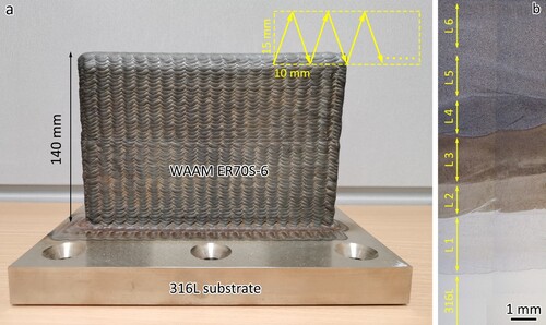
Table 2. Parameters used for the WAAM-plasma process.
Throughout the WAAM process, the entire set-up was shielded by a polymeric film tank filled with high-purity Ar gas. The O2 content was regulated to approximately 1600 ppm, while Ar gas flow was used to provide additional protection to the melt pool at a rate of 8 L/min. The pressure within the Ar tank was maintained as equivalent to atmospheric pressure. The dimensions of the WAAM-built ER70S-6 wall were 200 mm (L) × 140 mm (H) × 18 mm (W).
The temperature of the deposited wall was monitored using an infrared thermometer. The interpass temperature of 200°C was chosen to achieve an acceptable interpass waiting time. When the temperature cools below 200°C, the next layer will start to print.
2.3. Microstructure characterisation
The samples underwent a standard preparation process for microstructural analysis, beginning with grinding using progressively finer SiC papers (ranging from 320 to 4000 grit), followed by polishing with silicon oxide polishing suspension (OPS, Struers). Subsequently, the samples were etched with a 4% Nital solution for about 4 s. For observing the microstructures of the first and second layers of the interface, Kalling's No 2 reagent was applied for about 10 s. A self-mixed etching solution (HF: HNO3: H2O = 1: 6: 12) was also used for the microstructural observation of the first and second layers. Microstructures were examined using an optical microscope (Carl Zeiss Axioskop 2 MAT), a scanning electron microscope (JEOL JSM-7600F) and electron backscattered diffraction (EBSD, Oxford Instruments) with a Nordlys detector. SEM observations were conducted at an accelerating voltage of 10 kV, while EBSD measurements used a step size of 0.8 μm and an accelerating voltage of 20 kV.
2.4. Mechanical properties
The microhardness tests were conducted with a load of 300 g and a dwell time of 15 s. The tensile samples were machined using an electric wire cutting from the printed blocks. The tensile tests were conducted following the ASTM E8/E8M − 16a standard. For each condition, three tensile samples were tested at room temperature at a constant strain rate of 2.5 × 10⁻⁴ s−1 using a Shimadzu AG-XD plus (Kyoto, Japan) universal tensile testing machine. The gauge dimensions of the tensile samples were 30 mm × 6 mm × 3 mm. A non-contact video extensometer was employed to measure the tensile strain.
2.5. DIC analysis
DIC analysis was conducted using the MATLAB R2023b software to analyse the localised deformation behaviour. The tensile sample was painted white. Then black paint was sprayed on the white paint. The black spray was in the shape of a micron-sized particle, which was used for the measurement of localised strain. A high-resolution video was taken during the tensile test. The video was used for the DIC analysis.
3 Results
3.1. Macrostructure
(a) shows a photo of the WAAM-built ER70S-6 on a 316L substrate. The wall had a dimension of 200 mm × 140 mm × 20 mm. The overview of the macrostructure of the 316L/ER70S-6 interface after etching using 4% Nital is shown in (b). The 316L substrate and different layers are marked. L1 represents the first layer; L2 represents the second layer and so forth.
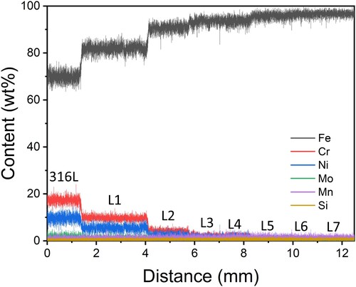
shows the EDS line scan of the 316L/ER70S-6 interface and the first few layers. Carbon was excluded because the EDS technology has a low accuracy for the measurement of carbon content due to the small atomic number. An obvious change in chemical composition can be observed in layer 1, layer 2 and layer 3. The chemical composition tends to stabilise after layer 4. The chemical composition change is a result of the dilution during the melting of the previous layers. During the melting of the first layer, the 316L substrate was partially melted. The first layer contains the elements from the 316L substrate and ER70S-6. A similar phenomenon occurred during the fabrication of the layers afterwards and therefore, a change in chemical composition was observed.
Figure 2. EDS line scan of the 316L/ER70S-6 interface and the first few layers.
The chemical composition of different layers was further measured using EDS mapping. The results are listed in .
Table 3. Chemical composition (wt%) of different layers measured using EDS mapping.
(a) shows the EBSD orientation map of the 316L substrate. It has a fully austenitic microstructure. Equiaxed grains with a high fraction of ∑3 twin boundaries (60°) were observed. The average grain size is 21.8 µm as measured using EBSD-based high-angle grain boundary (>15°). The fraction of the twin boundary was about 23%.
Figure 3. EBSD orientation maps of the 316L substrate and the first six layers of the WAAM-fabricated bimetal structure, (a) 316L substrate, (b) layers 1 and 2, (c) layer 3, (d) layer 4, (e) layer 5 and (f) layer 6.
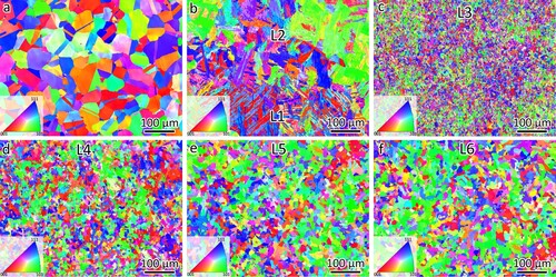
(b–f) shows the microstructures observed using EBSD of the first six layers of the WAAM-fabricated bimetal structure. A fully body-centred cubic structure was observed in the WAAM deposits. (b) presents the microstructure of layer 1 and layer 2, which is highly likely to be the bainite phase. The bainite lath was wider than that in the first layer. (c) shows the microstructure of layer 3. Fine and equiaxed grains were observed in layer 3. The average grain size was measured at 5.2 µm. The grains in the fourth, fifth and sixth layers present an equiaxed morphology. The decrease in Cr and Ni content increased the grain size, as shown in (d–f). The average grain size was 7.0 µm for layer 4, 10.9 µm for layer 5 and 12.2 µm for layer 6. The microstructures of the layers above layer 6 are similar to layer 6 and therefore, they are not shown here.
Typically, during the WAAM process, the grain size of earlier layers tends to increase due to the reheating caused by subsequent layers. However, contrary to this expectation, our current study observed that the grain size increases as each new layer is printed. The mechanism is attributed to the change in chemical composition.
WAAM-built ER70S-6 typically presents non-uniform microstructures [Citation17,Citation21,Citation22]. The grain size ranges from about 5 µm to 50 µm. However, equiaxed grains were observed in the current work, as shown in (f). The underlying mechanism was attributed to the high heat input of the plasma WAAM process. The high heat input leads to extra energy accumulated in the WAAM-built layers and in-situ annealing and thus equiaxed grains were observed [Citation29].
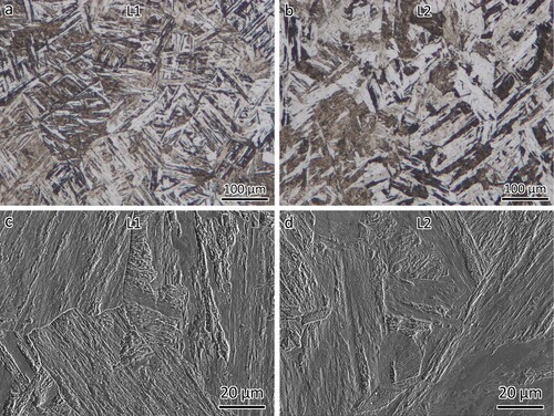
The optical images (etched using Kalling's No 2) in (a, b) show the microstructures of layers 1 and 2 of the WAAM-fabricated bimetal structure. Notably, a plate-like microstructure was observed in the first two layers. The width of the plate is larger for layer 2 than that of layer 1. Specifically, the width of the plate was 3.6 µm for layer 1 and 12.7 µm for layer 2, as measured from (a, b). Further examination of the microstructures (etched using self-mixed etching solution (HF: HNO3: H2O = 1: 6: 12) of layers 1 and 2) of the two layers was conducted using SEM, as shown in (c, d). With detailed observation using SEM, it can be seen that the plate-like microstructure in layers 1 and 2 could be bainite.
Figure 4. Optical images showing the bainite microstructure in (a) layer 1 and (b) layer 2. SEM images showing the bainite microstructure in (c) layer 1 and (d) layer 2.
SEM images (etched using Kalling's No 2) of layers 1 and 2 are shown in (a, b). Thin strips can be observed which could be the retained austenite which is similar to the TIG-welded 15-5 PH stainless steel [Citation30]. 15-5 PH stainless steel contains 15% Cr and 5% Ni. Layer 1 contains about 10% Cr and 5% Ni. Therefore, it is reasonable to make a comparison. The retained austenite in bainite would benefit from high toughness because of the deformation-induced austenite to martensite phase transformation. The phase transformation could absorb energy and thus enhance toughness [Citation31].
Figure 5. SEM images showing the microstructures of (a) layer 1, (b) layer 2, (c) layer 3, (d) layer 4, (e) layer 5 and (f) layer 6.
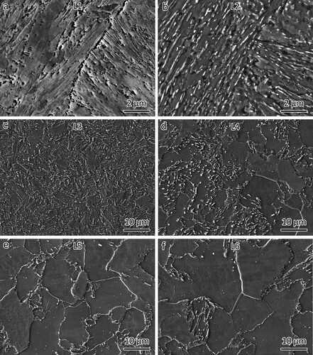
EBSD results in illustrated the change in grain size. Here, the SEM images show the same tendency for layers 3, 4, 5 and 6. Layers 3 and 4 consist of granular bainite and ferrite phases, as shown in (c) and (d), respectively. The formation of bainite is a result of the low alloying elements (Cr, Ni, Mo, etc.) in these layers. Equiaxed ferrite and cementite phases were observed in layer 5 and layer 6, as shown in (c) and (d), respectively. The cementite phase is mainly located along the grain boundaries.
A gradual change in microstructures has been obtained from layers 1 to 6. The main reason for the change was the element dilution as shown in .
Based on the CALPHAD method [Citation32], thermodynamic simulations were performed using the Thermo-Calc software coupled with the TCFE-9 database to determine the equilibrium phase fractions across varying temperatures, as shown in . The chemical composition was defined according to the 31 L substrate, layer 1, layer 2 and ER70S-6. Deviations from conventional expectations in phase fractions were observed. Typically, 316L is regarded as a fully austenitic alloy. However, a high fraction of the ferrite phase and sigma phase was generated. The sigma phase occurs when a Fe-Cr alloy experiences long-term exposure to high-temperature annealing [Citation33]. Consequently, it is suggested that the thermodynamic simulations may not accurately reflect the actual phase compositions in the current study. It is still of a reference value. Exploring equilibrium solidification could enhance the comprehension of the microstructures within the interlayer.
Figure 6. Thermo-Calc equilibrium simulations showing the volume phase fractions as a function of temperatures using the chemical composition of (a) 316L substrate, (b) layer 1, (c) layer 2 and (d) ER70S-6.
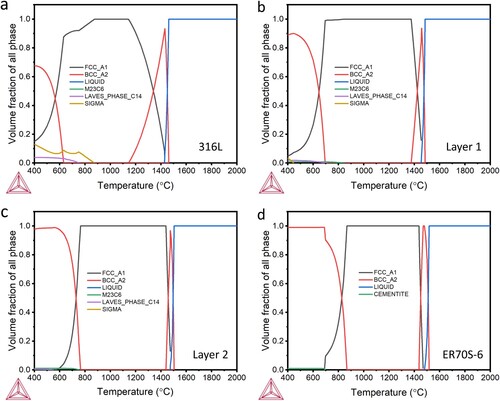
According to the diagrams, both layers 1 and 2 experienced the following phase transformation during cooling: L → L + δ → L + δ + γ → γ + α. It should be noted that this solidification mode was simulated at thermodynamic equilibrium without the use of any kinetic parameters (i.e. assuming infinite diffusion of all elements in all phases).
The melting point can also be obtained through the thermodynamic simulations. The melting point is 1430°C for 316L, 1454°C for layer 1, 1474°C for layer 2 and 1470°C for ER70S-6.
3.2. Mechanical properties
The microhardness profile, containing the 316L substrate and the first six layers, is shown in . The microhardness of the 316L is about 179.6 HV. The highest microhardness value was observed at layer 1, which was 336.9 ± 6.3 HV. The microhardness decreases with the increase of layers. The microhardness was 302.7 ± 5.7 HV for layer 2, 274.6 ± 4.2 HV for layer 3 and 188.5 ± 9.6 HV for layer 4. Layers 5 and 6 show a similar microhardness, which was about 160 HV. Comparable microhardness was observed for the layers above layer 6.
Figure 7. Microhardness profile of the 316L substrate and the first six layers.
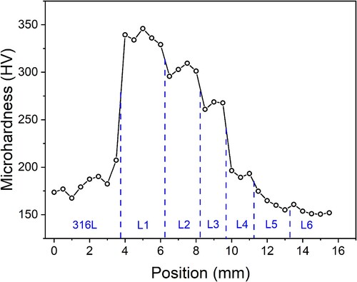
Bainite is generally stronger than ferrite due to its finer microstructure and presence of carbides [Citation34]. Therefore, the first and second layers have a higher microhardness than the rest. Since the microstructure of the bainite in the first layer is finer than that in the second layer, the first layer is harder than the second layer. The decrease in microhardness of the rest layers is due to the absence of bainite and the increase in grain size.
(a) shows the tensile stress–strain curves of the 316L substrate, WAAM-built ER70S-6 in vertical direction and the 316L/ER70S-6 bimetal joint. A close-up of the tensile curves near their yielding points is shown in (b). The detailed tensile properties are listed in .
Figure 8. (a) Tensile curves of the 316L/ER70S-6 joint, WAAM-built ER70S-6 in vertical direction, (b) a close-up of tensile curves near their yielding points; (c) A photo showing the tensile sample of the 316L/ER70S-6 bimetal joint before and after the tensile test. Fractography of (d) ER70S-6 and (e) 316L.
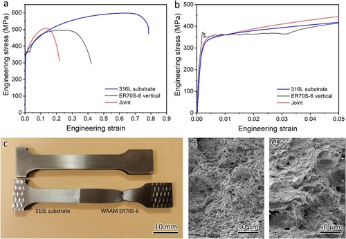
Table 4. Tensile properties of 316L/ER70S-6 joint, WAAM-built ER70S-6 and the 316L substrate.
The yielding of the WAAM-built ER70S-6 exhibited a serrated phenomenon. The serrated flow behaviour is named dynamic strain ageing (DSA) or Portevin-Le-Chatelier (PLC) effect which is related to the dynamic interaction between diffusing solute atoms and dislocations [Citation35]. Rafieazad et al. [Citation21] fabricated ER70S-6 using a gas metal arc welding (GMAW) WAAM process. The yield strength was 396 ± 26 MPa and the UTS was 503 ± 21 MPa with a small elongation at 13%. The higher yield strength was obtained compared to the current work. The underlying reason was the fine and non-uniform microstructures resulting from the GMAW WAAM process. The small elongation was likely caused by delamination, which might have resulted from the severe oxidation occurring within the layers. The high heat input of the plasma WAAM process used in this work introduced in-situ annealing to the ER70S-6 [Citation29]. Thus, the grains are uniform and equiaxed and the yield strength obtained using the plasma WAAM process is lower.
The 316L has a high elongation which has been frequently observed because of its austenitic microstructure. The 316L/ER70S-6 bimetal joint showed a similar yield strength and UTS to the WAAM-built ER70S-6. The elongation of the 316L/ER70S-6 bimetal joint was much lower than that of the WAAM-built ER70S-6. After the tensile test, the 316L/ER70S-6 bimetal joint fractured at the ER70S-6 side, as shown in (c). Deformation was also observed at the 316L substrate side. SEM image in (d) shows the fractograph of WAAM-built ER70S-6. A fractograph of 316L was taken after the tensile test of the substrate and shown in (e). Dimples were observed in both materials, indicating ductile fracture.
4 Discussion
4.1. Deformation behaviour of the 316L/ER70S-6 bimetal joint
The 316L/ER70S-6 bimetal joint showed a similar yield strength and UTS to the WAAM-built ER70S-6. However, all the tensile samples were fractured at the ER70S-6 side. Moreover, the microhardness along the bimetal joint is significantly different (). During the tensile test, the deformation of the bimetal joint would be non-uniform. Therefore, it would be interesting to study the deformation behaviour during the tensile test.
The DIC method was used to track and quantify the localised deformation. The result is shown in . A video showing the DIC result is provided in the supplementary information. The red colour represents a high localised strain, while the blue colour represents a low localised strain. The values of the highest localised strain and the total strain are also given.
Figure 9. DIC study showing the colour map of the localised deformation of 316L/ER70S-6 bimetal joint during the tensile test.
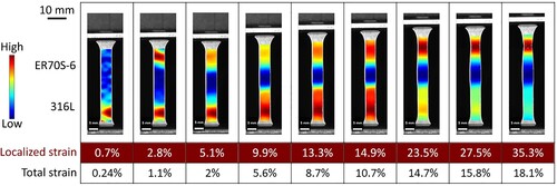
From the DIC result, it can be seen that the 316L side yields first at the small total strain of 0.24%. At the total strain of 1.1%, the WAAM-fabricated ER70S-6 side starts to deform. During the tensile test, no deformation was observed at the interlayer since it has the highest strength according to the microhardness profile. The DIC result revealed that the highest tensile strain at the 316L side was around 20% at the total train of 12.7% which was the strain at the UTS point. After that, deformation only occurred at the WAAM-fabricated ER70S-6 side. Therefore, it can be concluded that the deformation was shifted from the 316L side to the WAAM-fabricated ER70S-6 side during the tensile test.
During the tensile test, there is almost no deformation at the interlayer, primarily attributable to its high strength, as evidenced by the microhardness profile depicted in . To gain a bimetal joint with good performance, the mechanical property at the interface is important. Ideally, the mechanical strength at this critical interface should surpass that of the base materials to effectively mitigate potential interface failures.
To verify the deformation behaviour observed using the DIC method, a detailed examination was conducted of the tensile tests. The tensile strain was tested using a video extensometer. Before the tensile test, two black lines were marked, as shown in the insert of (a). During the tensile test, the force was recorded by the force sensor. The strain was measured by measuring the distance change of the two black lines using the video extensometer.
Figure 10. Tensile curves of 316L/ER70S-6 bimetal with the strain measurement from different parts of the tensile sample, (a) from the whole sample, (b) only from the 316L side.
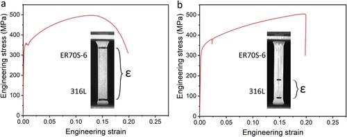
(a) shows the tensile curve of the 316L/ER70S-6 bimetal when the strain was measured from both the 316L side and the ER70S-6 side. The DIC analysis revealed that the 316L yielded first and then ER70S-6 deformed later at the small total strain of 1.1%. A serrated region of the tensile curve in (a) was observed at the strain of around 1%. The serrated region is recognised as the yielding of the ER70S-6 side.
(b) shows the tensile curve of the 316L/ER70S-6 bimetal when the strain was measured from only the 316L side. During the tensile test, the two black lines were only marked at the 316L region, and therefore, the deformation of the ER70S-6 was not recorded. During the yielding of the ER70S-6, the force changes upon the strain increasing. However, as shown in (b), the strain of the ER70S-6 was not recorded. Therefore, only a sharp drop of the force was observed in the tensile curve at the strain of about 2.5%. The tensile deformation of the 316L was about 20%, which proves that the DIC analysis is reliable. There was no deformation at the 316L side after 20% strain. The deformation of ER70S-7 during necking of the tensile sample was not recorded and therefore, a sharp drop was observed at the tensile strain of 20%.
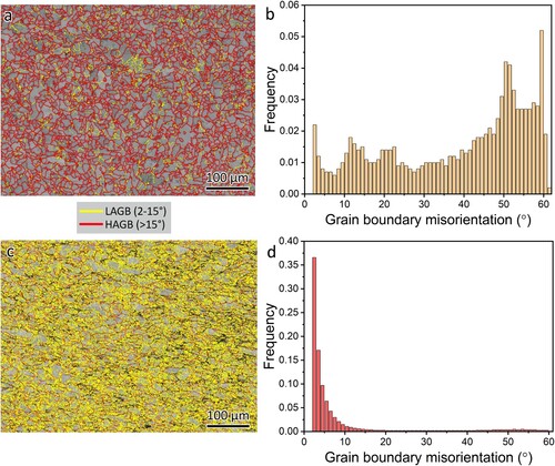
shows the microstructure evolution of the 316L of the bimetal observed using BESD. The grain boundary map is shown in (a) and the grain boundary misorientation distribution is shown in (b). It can be seen that the as-received 316L possesses a high fraction of twin boundary and a low fraction (7.4%) of low-angle grain boundary (LAGB, 2-15˚). The as-received 316L was forged followed by annealing. Therefore, a high fraction of the annealing twin boundary was obtained. After the tensile test, the 316L side of the bimetal joint deformed about 20%. A high fraction (48.1%) of LAGBs was observed, as shown in (c, d). The formation of the LAGBs could be the result of grain rotation during the tensile test. Grain rotation during a tensile test refers to the reorientation of the crystal lattice structure within the grains of a material as it undergoes deformation under tensile loading. To accommodate this deformation, the grain rotation occurs.
Figure 11. Microstructure evolution of the 316L side of the bimetal joint, (a) EBSD grain boundary map and (b) grain boundary misorientation distribution of the as-received 316L, (c) EBSD grain boundary map and (d) grain boundary misorientation distribution of the 316L after the tensile test.
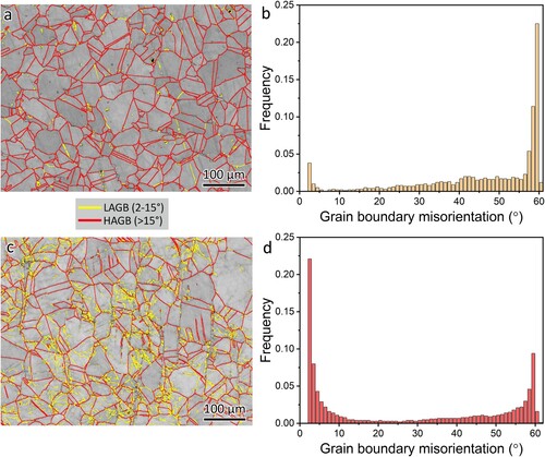
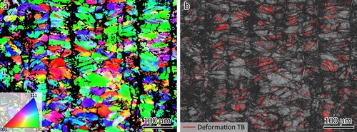
Deformation twinning has been frequently observed in 316L after the tensile test [Citation36]. However, at the tensile strain of 20%, almost no deformation twin boundary was observed ((c)). EBSD study was also conducted on the 316L substrate after fracture, as shown in , revealing a greater abundance of deformation twin boundaries. Byun et al. [Citation37,Citation38] proposed that the deformation mechanism comprises small stacking faults within the stress range of 400–600 MPa, while deformation twinning occurs at stresses exceeding 600 MPa. It means for forged or wrought 316L, deformation twinning only happens at a large tensile strain. Our observations align with the findings presented in the aforementioned work. Notably, deformation twinning occurs relatively earlier in LPBF-fabricated 316L. Zhai et al. [Citation39] observed deformation twinning at the tensile strain of 10% for LPBF-fabricated 316L. Similar results were observed by Wang et al. [Citation40] as well.
Figure 12. EBSD study of the 316L substrate after fracture, (a) orientation map and (b) distribution of deformation twin boundaries. TB: twin boundary.
shows the microstructure evolution of the WAAM-fabricated ER70S-6 of the bimetal observed using BESD. The grain boundary map is shown in (a) and the grain boundary misorientation distribution is shown in (b). The fraction of LAGBs was 16.0% for the as-built ER70S-6. (c) shows the grain boundary map of the WAAM-fabricated ER70S-6. The position of the EBSD measurement for fractured ER70S-6 was close to the fracture point. A high fraction of LAGBs was observed. (d) shows the grain boundary misorientation distribution. The fraction of LAGB was 86.8%. The high fraction of LAGB is caused by grain rotation during the tensile test.
Figure 13. Microstructure evolution of the WAAM-fabricated ER70S-6 side of the bimetal joint, (a) EBSD grain boundary map and (b) grain boundary misorientation distribution of the ER70S-6, (c) EBSD grain boundary map and (d) grain boundary misorientation distribution of the ER70S-6 after fracture.
4.2. Prospective for alloy design
AM offers a new opportunity for the fabrication of high-performance alloys. For example, according to ASTM A240/A240M-19, 316L has a low strength. Its minimum yield strength is 170 MPa; minimum is 485 MPa and minimum elongation is 40%. However, laser powder bed fusion (LPBF) fabricated 316L shows significantly increased mechanical property. Its yield strength is usually around 600 MPa with an elongation at about 50% [Citation39,Citation41–44].
AM also offers opportunities for the fabrication of new alloys [Citation45]. Zhai et al. [Citation46] studied the Ti-modified 316L through the LPBF process. Pure Ti powder was mixed with 316L powder. The 316L-Ti has refined grains with increased UTS. The Ti-6Al-4V alloy has been frequently studied using the LPBF process. However, the LPBF-processed Ti-6Al-4V usually has large β-grains and α′ lath. The addition of Ni through in-situ alloying can significantly refine the grains [Citation47,Citation48]. Wei et al. [Citation49] fabricated a Fe-Al functional graded material. During the LPBF process, the pre-mixed powders with different portions of Fe and Al were placed in the powder chamber. A gradient change in the composition of the printed blocks along the building direction can be obtained. Wen et al. [Citation50] created a novel powder recoating system to spread CoCrMo powder and Inconel 718 powder with gradient composition at the same layer to achieve a gradient composition change in the LPBF-fabricated alloy. After the characterisation of the alloy, an optimised composition can be achieved according to the desired application.
WAAM process could also be used for new alloy designs. Shen et al. [Citation51] fabricated AlCoCrFeNi high-entropy alloy using the WAAM process through in-situ alloying. The feedstock was a twisted wire combining 304 L, pure Al, Co, Fe and Ni wires. The WAAM-fabricated AlCoCrFeNi high-entropy alloy has a high yield strength of 816 MPa. Fabrication of new alloys by manipulating the ratio of the feeding multiple wires could also be applied. Wang et al. [Citation52] fabricated TiAl alloy using the twin wire WAAM process. The composition of the TiAl alloy was manipulated by alternating the wire feeding speed of Al and Ti wires. TiAl alloy with multiple Al contents (42%, 45%, 48% and 51%) has been successfully manufactured.
The present investigation achieved a gradient shift in composition within the interlayer. The first layer has a chemical composition of Fe-10Cr-5.5Ni-1Mo-1Mn. The high content of Cr and Ni is advantageous for corrosion and oxidation resistance. The as-fabricated steel exhibits a high microhardness of 336.9 HV, indicating good mechanical properties. The second layer features a chemical composition of Fe-4Cr-2Ni-1Mn with 0.5 wt% Mo which presents as a martensitic stainless steel. Cr and Ni are beneficial in terms of corrosion and oxidation resistance. Moreover, the reduced alloying element content contributes to a lower cost of the steel. Through appropriate post-heat treatment, further enhancement of mechanical properties is achievable. Consequently, this approach holds promise for the development of novel alloys through the dilution of different materials or a combination of different feeding wires.
5. Conclusions
In summary, this work studied the fabrication of bimetal structures using the plasma WAAM process. A low-carbon steel wire ER70S-6 was directly built onto a 316L substrate. The microstructures and mechanical properties are investigated. The deformation behaviour of the bimetal structure is analysed using DIC. It is hoped that our work will stimulate interest to carry out further study to investigate the WAAM-built muilti-material structures. Based on the studies presented in this work, the following conclusions can be drawn:
The bimetal joint of 316L/ER70S-6 can be successfully fabricated using the WAAM process. A gradient change in composition due to dilution was observed at the interlayer which consists of six layers.
The first layer with the chemical composition of Fe-10Cr-5.5Ni-1Mo-1Mn and the second layer with the chemical composition of Fe-4Cr-2Ni-1Mn-0.5Mo exhibit a bainite microstructure. There is an increase in grain size from layer 3 to layer 6.
The microhardness is high at 336.9 HV for layer 1 and 302.7 HV for 2. A decrease in microhardness was observed with the increase of the building layer until layer 6. The WAAM-built ER70S-6 has a microhardness of about 160 HV.
The yield strength is 356.6 MPa and the UTS is 502.3 MPa for the bimetal joint of 316L/ER70S-6. During the tensile test, the 316L substrate side yields first and then the deformation shifts to the ER70S-6 side during the tensile test.
WAAM for bimetal structure holds the potential for the development of novel alloys.
Acknowledgements
The authors also acknowledge the support from Nanyang Technological University for access to the materials’ characterisation facilities.
Disclosure statement
No potential conflict of interest was reported by the author(s).
Data availability statement
The data that support the findings of this study are available on request from the corresponding author.
Additional information
Funding
References
- Lu HZ, Chen T, Liu LH, et al. Constructing function domains in NiTi shape memory alloys by additive manufacturing. Virtual Phys Prototyp. 2022;17(3):563–581. doi:10.1080/17452759.2022.2053821
- Zhai W, Wang P, Ng FL, et al. Hybrid manufacturing of γ-TiAl and Ti–6Al–4V bimetal component with enhanced strength using electron beam melting. Compos Part B: Eng. 2021;207:108587. doi:10.1016/j.compositesb.2020.108587
- Zhang K, Wang S, Liu W, et al. Characterization of stainless steel parts by laser metal deposition shaping. Mater Des. 2014;55:104–119. doi:10.1016/j.matdes.2013.09.006
- Ding D, Pan Z, Cuiuri D, et al. Wire-feed additive manufacturing of metal components: technologies, developments and future interests. Int J Adv Manuf Technol. 2015;81(1–4):465–481. doi:10.1007/s00170-015-7077-3
- Wynne Z, Buchanan C, Kyvelou P, et al. Dynamic testing and analysis of the world's first metal 3D printed bridge. Case Stud Constr Mater. 2022;17:e01541. doi:10.1016/j.cscm.2022.e01541
- Palmeira Belotti L, van Dommelen JAW, Geers MGD, et al. Influence of the printing strategy on the microstructure and mechanical properties of thick-walled wire arc additive manufactured stainless steels. J Mater Process Technol. 2024;324:118275. doi:10.1016/j.jmatprotec.2023.118275
- Wang L, Xue J, Wang Q. Correlation between arc mode, microstructure, and mechanical properties during wire arc additive manufacturing of 316L stainless steel. Mater Sci Eng A. 2019;751:183–190. doi:10.1016/j.msea.2019.02.078
- Horgar A, Fostervoll H, Nyhus B, et al. Additive manufacturing using WAAM with AA5183 wire. J Mater Process Technol. 2018;259:68–74. doi:10.1016/j.jmatprotec.2018.04.014
- Qi Z, Cong B, Qi B, et al. Properties of wire + arc additively manufactured 2024 aluminum alloy with different solution treatment temperature. Mater Lett. 2018;230:275–278. doi:10.1016/j.matlet.2018.07.144
- Wang Y, Chen X, Su C. Microstructure and mechanical properties of Inconel 625 fabricated by wire-arc additive manufacturing. Surf Coat Technol. 2019;374:116–123. doi:10.1016/j.surfcoat.2019.05.079
- McAndrew AR, Alvarez Rosales M, Colegrove PA, et al. Interpass rolling of Ti-6Al-4V wire + arc additively manufactured features for microstructural refinement. Addit Manuf. 2018;21:340–349. doi:10.1016/j.addma.2018.03.006
- Lyu Z, Sato YS, Xu W, et al. Simultaneous enhancements of strength and ductility of wire arc additive manufactured 17-4PH steel via intrinsic heat treatment. J Mater Process Technol. 2023;321:118149. doi:10.1016/j.jmatprotec.2023.118149
- Caballero A, Ding J, Ganguly S, et al. Wire + Arc additive manufacture of 17-4 PH stainless steel: Effect of different processing conditions on microstructure, hardness, and tensile strength. J Mater Process Technol. 2019;268:54–62. doi:10.1016/j.jmatprotec.2019.01.007
- Bandyopadhyay A, Zhang Y, Onuike B. Additive manufacturing of bimetallic structures. Virtual Phys Prototyp. 2022;17(2):256–294. doi:10.1080/17452759.2022.2040738
- Bandyopadhyay A, Heer B. Additive manufacturing of multi-material structures. Mater Sci Eng: R: Rep. 2018;129:1–16. doi:10.1016/j.mser.2018.04.001
- Wei C, Li L. Recent progress and scientific challenges in multi-material additive manufacturing via laser-based powder bed fusion. Virtual Phys Prototyp. 2021;16(3):347–371. doi:10.1080/17452759.2021.1928520
- Ahsan MRU, Tanvir ANM, Seo G-J, et al. Heat-treatment effects on a bimetallic additively-manufactured structure (BAMS) of the low-carbon steel and austenitic-stainless steel. Addit Manuf. 2020;32:101036. doi:10.1016/j.addma.2020.101036
- Marques LFN, Santos EBF, Gerlich AP, et al. Fatigue life assessment of weld joints manufactured by GMAW and CW-GMAW processes. Sci Technol Weld Joining. 2017;22(2):87–96. doi:10.1080/13621718.2016.1194735
- Ribeiro RA, Assunção PDC, Braga EM, et al. Welding thermal efficiency in cold wire gas metal arc welding. Weld World. 2021;65(6):1079–1095. doi:10.1007/s40194-021-01070-x
- Dornelas PHG, Payão Filho JC, Farias FWC, et al. Influence of the interpass temperature on the microstructure and mechanical properties of the weld metal (AWS A5.18 ER70S-6) of a narrow gap welded API 5L X70 pipe joint. Int J Press Vessels Pip. 2022;199:104690. doi:10.1016/j.ijpvp.2022.104690
- Rafieazad M, Ghaffari M, Vahedi Nemani A, et al. Microstructural evolution and mechanical properties of a low-carbon low-alloy steel produced by wire arc additive manufacturing. Int J Adv Manuf Technol. 2019;105(5-6):2121–2134. doi:10.1007/s00170-019-04393-8
- Rafieazad M, Nemani AV, Ghaffari M, et al. On microstructure and mechanical properties of a low-carbon low-alloy steel block fabricated by wire arc additive manufacturing. J Mater Eng Perform. 2021;30(7):4937–4945. doi:10.1007/s11665-021-05568-9
- Ermakova A, Mehmanparast A, Ganguly S, et al. Investigation of mechanical and fracture properties of wire and arc additively manufactured low carbon steel components. Theor Appl Fract Mech. 2020;109:102685. doi:10.1016/j.tafmec.2020.102685
- Ermakova A, Mehmanparast A, Ganguly S, et al. Fatigue crack growth behaviour of wire and arc additively manufactured ER70S-6 low carbon steel components. Int J Fract. 2022;235(1):47–59. doi:10.1007/s10704-021-00545-8
- Ermakova A, Razavi J, Berto F, et al. Uniaxial and multiaxial fatigue behaviour of wire arc additively manufactured ER70S-6 low carbon steel components. Int J Fatigue. 2023;166:107283. doi:10.1016/j.ijfatigue.2022.107283
- Chao Q, Cruz V, Thomas S, et al. On the enhanced corrosion resistance of a selective laser melted austenitic stainless steel. Scr Mater. 2017;141:94–98. doi:10.1016/j.scriptamat.2017.07.037
- Alali M, Todd I, Wynne BP. Through-thickness microstructure and mechanical properties of electron beam welded 20 mm thick AISI 316L austenitic stainless steel. Mater Des. 2017;130:488–500. doi:10.1016/j.matdes.2017.05.080
- Agrawal AK, Singh A. Limitations on the hardness increase in 316L stainless steel under dynamic plastic deformation. Mater Sci Eng A. 2017;687:306–312. doi:10.1016/j.msea.2017.01.066
- Zhai W, Guo Y, Aishwarya, et al. Wire arc additive manufacturing of ER70S-6/S355 bimetal component. Mater Sci Eng A. 2024;900:146498. doi:10.1016/j.msea.2024.146498
- Niu J, Cui B, Jin H, et al. Effect of post-weld aging temperature on microstructure and mechanical properties of weld metal of 15-5 PH stainless steel. J Mater Eng Perform. 2020;29(11):7026–7033. doi:10.1007/s11665-020-05193-y
- Caballero FG, Roelofs H, Hasler S, et al. Influence of bainite morphology on impact toughness of continuously cooled cementite free bainitic steels. Mater Sci Technol. 2012;28(1):95–102. doi:10.1179/1743284710Y.0000000047
- Andersson J-O, Helander T, Höglund L, et al. Thermo-Calc & DICTRA, computational tools for materials science. Calphad. 2002;26(2):273–312. doi:10.1016/S0364-5916(02)00037-8
- Tang X. Sigma phase characterization in AISI 316 stainless steel. Microsc Microanal. 2005;11(S02):78–79. doi:10.1017/S143192760550374X
- Bhadeshia HKDH. Bainite in steels: Theory and practice. London: Maney Publishing; 2015.
- Zhang Y, Liu JP, Chen SY, et al. Serration and noise behaviors in materials. Prog Mater Sci. 2017;90:358–460. doi:10.1016/j.pmatsci.2017.06.004
- Zhang W, Wang X, Hu Y, et al. Quantitative studies of machining-induced microstructure alteration and plastic deformation in AISI 316 stainless steel using EBSD. J Mater Eng Perform. 2018;27(2):434–446. doi:10.1007/s11665-018-3129-9
- Byun TS. On the stress dependence of partial dislocation separation and deformation microstructure in austenitic stainless steels. Acta Mater. 2003;51(11):3063–3071. doi:10.1016/S1359-6454(03)00117-4
- Byun TS, Lee EH, Hunn JD. Plastic deformation in 316LN stainless steel – characterization of deformation microstructures. J Nucl Mater. 2003;321(1):29–39. doi:10.1016/S0022-3115(03)00195-8
- Zhai W, Zhou W, Nai SML. Grain refinement and strengthening of 316L stainless steel through addition of TiC nanoparticles and selective laser melting. Mater Sci Eng A. 2022;832:142460. doi:10.1016/j.msea.2021.142460
- Wang X, Muñiz-Lerma JA, Attarian Shandiz M, et al. Crystallographic-orientation-dependent tensile behaviours of stainless steel 316L fabricated by laser powder bed fusion. Mater Sci Eng A. 2019;766:138395. doi:10.1016/j.msea.2019.138395
- Zhong Y, Liu L, Zou J, et al. Oxide dispersion strengthened stainless steel 316L with superior strength and ductility by selective laser melting. J Mater Sci Technol. 2020;42:97–105. doi:10.1016/j.jmst.2019.11.004
- Liu L, Ding Q, Zhong Y, et al. Dislocation network in additive manufactured steel breaks strength–ductility trade-off. Mater Today. 2018;21(4):354–361. doi:10.1016/j.mattod.2017.11.004
- Yin YJ, Sun JQ, Guo J, et al. Mechanism of high yield strength and yield ratio of 316L stainless steel by additive manufacturing. Mater Sci Eng A. 2019;744:773–777. doi:10.1016/j.msea.2018.12.092
- Voisin T, Forien J-B, Perron A, et al. New insights on cellular structures strengthening mechanisms and thermal stability of an austenitic stainless steel fabricated by laser powder-bed-fusion. Acta Mater. 2021;203:116476. doi:10.1016/j.actamat.2020.11.018
- Clare AT, Mishra RS, Merklein M, et al. Alloy design and adaptation for additive manufacture. J Mater Process Technol. 2022;299:117358. doi:10.1016/j.jmatprotec.2021.117358
- Zhai W, Zhou W, Nai SML. Grain refinement of 316L stainless steel through in-situ alloying with Ti in additive manufacturing. Mater Sci Eng A. 2022;840:142912. doi:10.1016/j.msea.2022.142912
- Xiong Z, Pang X, Liu S, et al. Hierarchical refinement of nickel-microalloyed titanium during additive manufacturing. Scr Mater. 2021;195:113727. doi:10.1016/j.scriptamat.2021.113727
- Sui S, Chew Y, Weng F, et al. Achieving grain refinement and ultrahigh yield strength in laser aided additive manufacturing of Ti−6Al−4V alloy by trace Ni addition. Virtual Phys Prototyp. 2021;16(4):417–427. doi:10.1080/17452759.2021.1949091
- Wei S, Lau KB, Lee JJ, et al. Selective laser melting of Fe–Al alloys with simultaneous gradients in composition and microstructure. Mater Sci Eng A. 2021;821:141608. doi:10.1016/j.msea.2021.141608
- Wen Y, Zhang B, Narayan RL, et al. Laser powder bed fusion of compositionally graded CoCrMo-Inconel 718. Addit Manuf. 2021;40:101926. doi:10.1016/j.addma.2021.101926
- Shen Q, Kong X, Chen X. Fabrication of bulk Al-Co-Cr-Fe-Ni high-entropy alloy using combined cable wire arc additive manufacturing (CCW-AAM): Microstructure and mechanical properties. J Mater Sci Technol. 2021;74:136–142. doi:10.1016/j.jmst.2020.10.037
- Wang L, Shen C, Zhang Y, et al. Effect of Al content on the microstructure and mechanical properties of γ-TiAl alloy fabricated by twin-wire plasma arc additive manufacturing system. Mater Sci Eng A. 2021;826:142008. doi:10.1016/j.msea.2021.142008