
 ?Mathematical formulae have been encoded as MathML and are displayed in this HTML version using MathJax in order to improve their display. Uncheck the box to turn MathJax off. This feature requires Javascript. Click on a formula to zoom.
ABSTRACT
This study leverages the high manufacturing freedom of 3D printing technology to design a new type of three-dimensional elastic metamaterial with surface resonant units. This metamaterial uses chiral connecting rods and mass blocks on the surface to generate local resonance effects, achieving omnidirectional vibration isolation effects with both low frequency and wide bandwidth, and also has a certain load-bearing capacity. The mechanisms of local resonance bandgap generation are illustrated from the band structure and vibration modes at the edge frequency of the bandgap. The influence of structural geometric parameters and material properties on the bandgap is systematically investigated via finite element method. The transmission characteristics of the metamaterial are obtained through simulation and experiment, and the bandgap areas achieved from two methodologies match each other well. Through static compression tests, the compressive abilities of metamaterials with different frame thicknesses are studied, providing theoretical guidance and data support for engineering applications of balancing vibration isolation and load-bearing.
1. Introduction
Vibration issues are prevalent in many fields such as aerospace, vehicle engineering, civil construction, etc. They can affect the precision of instruments and equipment, shorten the lifespan of parts and components, and even cause serious damage to devices or buildings. Particularly, low-frequency vibrations below 500 Hz, due to their strong penetration, long propagation distance, and difficulty in isolation, have a greater impact on human production and life. Therefore, how to suppress low-frequency vibration has always been a problem to be solved urgently. Elastic metamaterials are usually periodic composite metamaterials composed of two or more different components in a specific arrangement and combination, exhibiting a variety of unique properties not found in natural materials, such as negative Poisson’s ratios [Citation1,Citation2], negative thermal expansion [Citation3], negative refraction [Citation4], waveguiding [Citation5], wave focusing [Citation6], and bandgap characteristics [Citation7–11]. Among these, the bandgap characteristics of elastic metamaterials can provide a valuable research perspective for solving vibration problems. This is exhibited by the ability of metamaterials to block the propagation of elastic waves within a specific frequency range, thereby achieving vibration isolation.
The bandgap of elastic metamaterials can be divided into Bragg scattering type [Citation12–15] and locally resonance type [Citation16–21] from the generation mechanism. The elastic waves that Bragg scattering elastic metamaterials can isolate have a wavelength and lattice constant on the same order of magnitude. This means that the cell size required to achieve low-frequency vibration isolation may even be up to several metres, but this is difficult to achieve in applications. On the other hand, the elastic waves that locally resonant elastic metamaterials can isolate have a wavelength far greater than its lattice constant, making it more suitable for low-frequency vibration isolation.
However, traditional locally resonant elastic metamaterials require at least two materials with high density and low elastic modulus to serve as the resonator and elastic layer respectively to achieve low-frequency vibration isolation effects [Citation20,Citation22–29]. These structures, as shown in , need to be manufactured and then assembled, which increases the complexity and cost of the process. The development of additive manufacturing technology has made the integrated moulding of elastic metamaterials possible, and also promoted the diversification of structural design [Citation30–37]. An et al. [Citation38] proposed a 3D printed three-dimensional chiral meta-plate lattice structure, with both sound and vibration isolation performance and a certain load-bearing capacity. However, the bandgap starting frequency reached 1927 Hz, and additional mass blocks need to be installed to achieve low-frequency vibration isolation. Jiang et al. [Citation39] designed a new type of 3D printed elastic metamaterial, which uses almost the entire base structure as a resonator, and extends elastic pillars to connect adjacent cells, with a lower frequency bandgap of 621∼732 Hz. Lin et al. [Citation40] designed a metamaterial with quasi-zero stiffness effect in three dimensions, with a bandgap frequency range as low as 49∼63 Hz, but the bandwidth is too narrow, and to achieve vibration isolation in a specific frequency segment, the displacement of pre-compression must be precisely controlled, which has poor adjustability. Ding et al. [Citation41] proposed a three-dimensional metamaterial based on the principle of inertial amplification by utilising translation-rotation coupling, with the vibration isolation effects in a larger frequency range of 601∼1504 Hz. Li et al. [Citation42] designed a truss-plate hybrid lattice metamaterial that is only half the size of traditional elastic metamaterials, yet possesses a bandgap width of 2.6 kHz and a specific energy absorption of 2.7 J/g.
Figure 1. Traditional multi-material locally resonant elastic metamaterials [Citation20,Citation22–29].
![Figure 1. Traditional multi-material locally resonant elastic metamaterials [Citation20,Citation22–29].](/cms/asset/0ccb4bfb-5f39-444f-a816-45fea1549830/nvpp_a_2382159_f0001_oc.jpg)
However, existing three-dimensional elastic metamaterials still struggle to achieve a bandgap that combines low frequency and wide bandwidth, while realise lightweight structures with a certain load-bearing capacity. In this study, we propose a three-dimensional elastic metamaterial with surface resonant units with the connecting rods and resonators distributed on the six external surfaces. What sets it apart from conventional three-dimensional elastic metamaterials is that the connecting rods and resonator of common metamaterials are usually located inside the structure. This structure can use the chiral structure formed by the low-stiffness connecting rods and surface resonators to generate and enhance the local resonance effect, and to produce an omnidirectional bandgap that combines low frequency and wide bandwidth. At the same time, this elastic metamaterial has a certain compressive performance and a lower relative density, expanding the engineering applications of such metamaterial and achieving lightweight. The structure designed in this paper is integrated manufactured using selective laser sintering (SLS) 3D printing technology, with nylon as the material. Vibration transmission experiments and compression experiments are carried out to validate the vibration isolation and compressive performance.
2. Theory and experiment
2.1. Design concepts
Locally resonant elastic metamaterials made of a single material cannot generate a low-frequency bandgap by changing the material density and elastic modulus. Therefore, the design relies on the coordination of different stiffness and volumes of each component of the structure to generate a low-frequency bandgap. Based on this, we designed a three-dimensional elastic metamaterial containing surface resonant units. The structure consists of a cubic frame and the connecting rods and resonators contained on the six surfaces of the frame. The connecting rods are slender folding rods, with four on each surface, one end connected to the frame, and the other end connected to the resonator, forming a chiral structure symmetrically distributed about the centre of the surface. The resonator is cylindrical and located at the centre of the frame surface. Each surface of this structure has a spring resonator system that can generate local resonance effects. The unique deformation mechanisms caused by the asymmetry of chiral rods on a single surface, can enhance the local resonance effect to generate directional low-frequency bandgaps. When similar structures present on each surface omnidirectional bandgaps with both low frequency and wide bandwidth shall be achieved.
The array and unit cell structure of this elastic metamaterial are shown in (a). The design and geometric parameter characteristics of a single surface of the structure are shown in (b), which are: frame side length a, frame thickness t, connecting rod width b, connecting rod segment lengths l1, l2, l3, l4, cylinder radius r, and cylinder height h ((a)). The corresponding first Brillouin zone of the simple cubic lattice is shown in (c). The relative density(ρr) of the structure is the ratio of the apparent density of the structure to that of the base material. Its size determines the degree of lightweighting of the structure and is a very important characteristic parameter. In this design, the calculation formula for relative density can be expressed as:
(1)
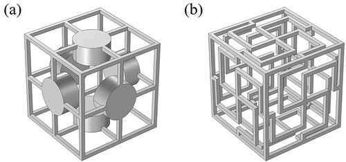
(1) To investigate the influence of the form of the connecting rods and the presence or absence of resonators on the low-frequency bandgap of this elastic metamaterial, we also designed two comparative models. One is a metamaterial where straight connecting rods replace the original chiral bent connecting rods ((a)), and the other is a metamaterial with the surface mass blocks removed ((b)). Then the comparative analysis of their band structures are conducted.
Figure 2. Three-dimensional elastic metamaterial with surface resonant units: (a) Array and unit cell structure (b) Design and geometric parameter characteristics of a single surface (c) Corresponding first Brillouin zone.
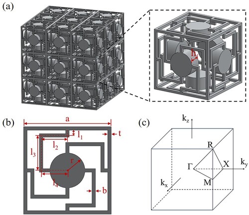
Figure 3. Comparison of metamaterials: (a) Metamaterial unit cell structure with straight rods replacing chiral bent rods (b) Metamaterial unit cell structure without surface mass blocks.
2.2. Theoretical methods for band structure analyses of metamaterial
In order to study the vibration isolation capability of three-dimensional elastic metamaterials, their band structures are calculated via finite element method. The wave equation for the propagation of elastic waves in the medium can be represented as:
(2)
(2) where λ and μ denote the Lame’s coefficients, ρ denotes the material density, u = (ux, uy, uz) denotes the displacement field and r = (x, y, z) denotes the position vector. Because the elastic metamaterial is periodically distributed in space, and periodic boundary conditions are applied to every two symmetric sides of the model, the propagation of elastic waves within it should satisfy Bloch’s theorem. That is, the displacement field u(r) can be represented as:
(3)
(3) where k = (kx, ky, kz) denotes the wave vector, and uk(r) is a periodic function that is the same as the periodicity of the metamaterial. After discretization, the eigenvalue equation for the unit cell is represented as:
(4)
(4) where K denotes the stiffness matrix, M denotes the mass matrix, and U denotes the displacement matrix. According to the direction of spatial periodic arrangement, combined with the application of EquationEquation (3)
(3)
(3) on the boundary of the unit cell model, the boundary displacement condition can be obtained as follow:
(5)
(5) where r denotes the position vector of the nodes on the boundary, and a denotes the base vector of the lattice vector of the elastic metamaterial. By letting the wave vector k scan the boundary of the first irreducible Brillouin zone and solving the eigenvalue equation of the unit cell, the band structure of the elastic metamaterial is calculated.
2.3. Finite element model of vibration isolation performance of metamaterial
This study uses the finite element analysis software COMSOL Multiphysics 6.1 for simulation calculations. In the calculation of the band structure, the scanning path of the wave vector is Γ-R-M-Γ-X-R-M-X, and Bloch-Floquet boundary conditions are applied on the three relative faces of the metamaterial to obtain the dispersion relation of the structure. A grid sensitivity analysis is also performed on the calculated results to ensure the rationality of the grid quantity.
The bandgap characteristics of elastic metamaterials are derived from the infinite array of unit cell structures, which cannot be realised in actual engineering applications. Therefore, it is necessary to calculate the vibration transmission characteristics of a finite number of elastic metamaterial unit cells to further validate the rationality of the bandgap characteristics in the band structure. The simulation model consists of 3 × 3 × 3 unit cells. An acceleration excitation (ain) is applied to the middle unit cell on one side of the model, and an acceleration response (aout) is received on the opposite side, while keeping the other boundaries free. Finally, the input and output acceleration values are substituted into EquationEquation (6)(6)
(6) to calculate the transmission characteristic curve of the model simulation.
(6)
(6)
2.4. Experimental test of metamaterial
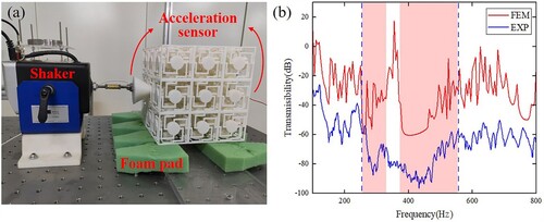
The vibration transmission characteristics of the elastic metamaterial proposed in this study were validated through experiments. Considering the feasibility of additive manufacturing of complex structures, the proposed array model was manufactured by SLS technology (EOS P760, Germany). The experimental setup is as follows: the test model is a 3 × 3 × 3 array model, which is isolated from the test bench at the bottom with a foam pad to simulate free boundaries as much as possible [Citation41,Citation43]. In order to facilitate the simultaneous connection of the shaker and the acceleration sensor on the model, a cone is installed in the centre of the side close to the shaker to expand the connection area, and another acceleration sensor is installed on the opposite side. During the experiment, the shaker (Model Shop K2007E01) generates longitudinal waves along the direction of the sensor connection line, and the scanning frequency range is 100 Hz to 800 Hz. The input and output vibration responses are received through the acceleration sensors (PCB 353-B15) at both ends. Finally, the transmission characteristic curve of the model experiment is calculated by analyzing the sensor data.
Four different frame thickness metamaterial unit cell samples were manufactured by 3D printing, and these samples were subjected to compression tests using a universal testing machine (PLD-5, China). All experiments were conducted at room temperature. During the experiment, the sample was placed in the centre of the base plate, the pressure head was controlled to press down at a constant speed of 3 mm/min, and the force and displacement data of the sensor were recorded.
3. Results and discussion
3.1. Simulation of band structure
In this section, considering the machining accuracy and manufacturing feasibility of 3D printing, a set of parameters is selected as an example. The material used is Nylon PA12, and the geometric parameters and material properties are shown in .
Table 1. Structural geometric parameters and material properties.
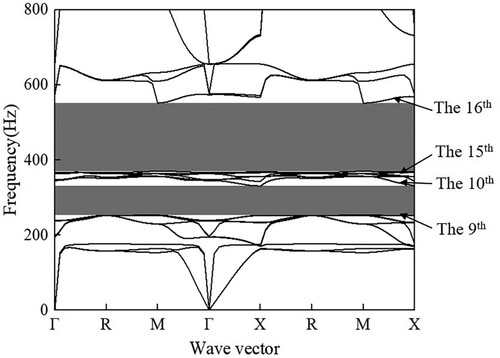
The band structure calculated for the proposed three-dimensional elastic metamaterial is shown in . For elastic metamaterials, the bandgap width represents the size of the frequency range at which the structure can achieve vibration isolation. This indicator is as important as the starting frequency of the bandgap. In this paper, the bandgap width is represented by the dimensionless relative bandgap width after normalisation, and the calculation formula is BGr = 2 (fup–flow) / (fup + flow), where fup and flow are the actual frequency values of the band at the upper and lower boundaries of the bandgap, respectively. The band structure shows that there are two complete bandgaps between the 9th and 10th bands and between the 15th and 16th bands, respectively. The bandgap ranges are 253∼331 Hz and 370∼552 Hz, respectively, indicating that vibrations in any direction within these two frequency ranges cannot pass through the metamaterial. These two bandgaps demonstrate excellent low-frequency vibration isolation performance of the structure, and the total relative bandwidth reaches 0.662 (0.267 + 0.395).
Figure 4. Band structure of the proposed elastic metamaterial.
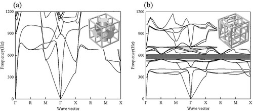
The band characteristics of the metamaterial with the original chiral bent connecting rod replaced by a straight connecting rod, and the metamaterial with the surface mass block removed, are shown in (a and b), respectively. It can be observed that the former does not have an omnidirectional bandgap in the low-frequency section, while the latter only opens an omnidirectional bandgap with a relative bandwidth of only 0.117. Such a narrow bandgap is not applicable in engineering. Therefore, it can be known that a certain mass of resonators and low-stiffness chiral connecting rods are necessary for this metamaterial to open a wide bandgap in the low frequency range.
Figure 5. Comparison of band structures of metamaterials: (a) Band structure of metamaterial with straight rods replacing chiral bent rods (b) Band structure of metamaterial without surface mass blocks.
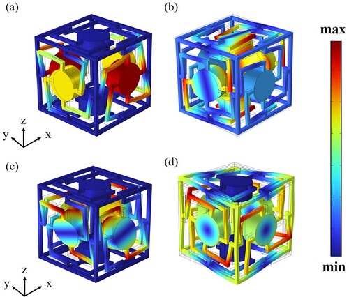
To further delve into the formation mechanisms of the bandgap, the vibration modes at the edge of the bandgap of the elastic metamaterial is analyzed. The edge vibration modes of the first bandgap are shown in (a and b). At its lower boundary, two groups of resonators in the x and y directions of the structure undergo in-plane translational motion, and under the constraint of the chiral connecting rod, a certain rotation occurs. At its upper boundary, two groups of resonators in the x and z directions of the structure respectively undergo out-of-plane overturning motion around the z and x directions, driving a slight twist in the frame. The edge vibration modes of the second bandgap are shown in (c and d). At its lower boundary, the vibration mode of the structure is similar to the upper boundary vibration mode of the first bandgap, with two groups of resonators in the x and y directions of the structure undergoing out-of-plane overturning motion around the y and x directions, respectively. At its upper boundary, two groups of resonators in the x and y directions of the structure undergo in-plane rotational motion under the influence of chirality, and the frame also undergoes a twist in the same direction. These vibration modes at the edge of the bandgap exhibit obvious local resonance characteristics, thus open a local resonance bandgap.
Figure 6. Vibration modes at the bandgap edges of the elastic metamaterial: (a) Vibration mode at the lower boundary of the first bandgap (b) Vibration mode at the upper boundary of the first bandgap (c)Vibration mode at the lower boundary of the second bandgap (d) Vibration mode at the upper boundary of the second bandgap.
3.2. The influence of geometric parameters of metamaterials on bandgap characteristics
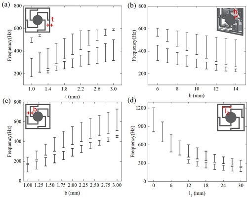
By keeping the lattice constant a, the radius r of the cylindrical base, and the segment lengths l1, l3, l4 of the connecting rod of the three-dimensional chiral local resonance type elastic metamaterial constant, the frame thickness t, the height h of the cylinder, the width b of the connecting rod, and the segment length l2 of the connecting rod were adjusted to explore the influence on the bandgap characteristics separately.
When the frame thickness t changes within 1∼3 mm, the frequency changes of the upper and lower edges of the elastic metamaterial bandgaps are shown in (a). As the frame thickness continues to increase, all bandgaps edge frequencies are continuously rising. Notably, when the frame thickness reaches 1.4 mm, the second bandgap originally above the first bandgap gradually closes and disappears, and a new bandgap appears below the first bandgap, which continues to expand. When the frame thickness reaches 2.2 mm, the frequency of the upper boundary of the original first bandgap hardly rise any further, so the bandgap starts to gradually shrink from here and eventually almost closes. The mass of the resonators changes along with the height of the cylinder. When the height h of the cylinder changes within 6∼14 mm, the frequency changes of the upper and lower edges of the elastic metamaterial bandgaps are shown in (b). As the height of the cylinder increases, both the frequencies of the upper and lower boundaries of the two bandgaps decrease, where the bandwidth of the first bandgap is continuously decreasing, while the bandwidth of the second bandgap is continuously increasing. When the rod width b changes within 1∼3 mm, the frequency changes of the upper and lower edges of the elastic metamaterial bandgaps are shown in (c). As the rod width continues to increase, the frequencies of the upper and lower boundaries of the two bandgaps are gradually increasing, where the bandwidth of the first bandgap is continuously decreasing, while the bandwidth of the second bandgap is continuously increasing. When the rod length l2 changes within 0∼30 mm, the frequency changes of the upper and lower edges of the elastic metamaterial bandgaps are shown in (d). When the segment length l2 of the connecting rod gradually increases from 0, initially there is only one bandgap in the band structure, and the bandgap frequency continues to move down while the bandwidth is gradually narrowing; when l2 increases to 12 mm, another bandgap appears below in the band diagram, as l2 continues to increase, the change rule of the original bandgap remains unchanged, and the frequency of the new bandgap also gradually moves down.
Figure 7. Influence of structural geometric parameters on bandgap characteristics: (a) Influence of the width of the connecting rod on bandgap characteristics (b) Influence of the height of the cylindrical resonators on bandgap characteristics (c) Influence of the width of the connecting rod on bandgap characteristics (d) Influence of the segment length l2 of the connecting rod on bandgap characteristics.
3.3. The influence of material properties of metamaterials on bandgap characteristics
To study the influence of material properties on the bandgap characteristics, three types of polymer materials and four types of metal materials were selected to compare their differences in bandgap characteristics, as shown in .
Table 2. Representative material properties selected for the model.
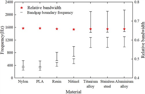
When the structural parameters are the same, the influence of different materials on the bandgap frequency and relative bandwidth is shown in . As can be seen from the figure, the choice of different materials has a significant impact on the bandgap frequency. If the influence of material density on the bandgap frequency is analyzed alone, the densities of titanium alloy and nitinol are not much different, but there is a significant difference in the bandgap frequency. However, the density difference between resin and nickel-titanium alloy is large, but the resulting bandgap frequency of them is close to each other, so no effective conclusion can be drawn. Similarly, no conclusion can be drawn from analyzing the influence of elastic modulus on the bandgap frequency alone. This indicates that the influence of material on the bandgap frequency can not be derived from either density or elastic modulus alone. However, when the parameter of shear wave speed ct in the material is introduced (, where E is the shear modulus of the material), the bandgap frequency of different materials is basically proportional to the shear wave speed in the material. This shows that under the same structural parameters, the comprehensive influence of material properties on the bandgap frequency can be well reflected by the shear wave speed. In addition, it can be seen from that regardless of which material is chosen, the relative bandwidth of the bandgap basically does not change. This indicates that for homogeneous elastic metamaterial, as long as the structural form and geometric parameters remains the same, the bandwidth proportion of the bandgap in the entire band structure is basically unchanged.
Figure 8. Influence of material properties on the bandgap boundary frequency and relative bandwidth.
3.4. Simulation of vibration transmission properties
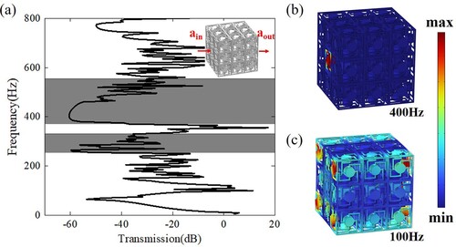
In this section, the vibration transmission characteristics of a finite number of elastic metamaterial unit cells is simulated. The transmission characteristic curve of the model is shown in (a). The two shaded parts are the bandgap areas, with frequencies of 255∼330 Hz and 370∼555 Hz, respectively, which match very well with the bandgap range in the band structure. The maximum vibration loss within the frequency range of the two bandgaps has reached −60 dB. (b) shows the displacement field of the model under the excitation frequency of 400 Hz (within the bandgap range). It can be clearly seen that at this time, the displacement only appears at the excitation point, and the vibration is well isolated. (c) shows the displacement field of the model under the excitation frequency of 100 Hz (outside the bandgap range). It can be seen that at this time, the vibration can still be transmitted through the model. These results prove that the array of a finite number of unit cells of this metamaterial has obvious vibration isolation effect within the bandgap range.
Figure 9. (a) Transmission characteristic curve of the finite element model (b) Displacement field of the model at an excitation frequency of 400 Hz (c) Displacement field of the model at an excitation frequency of 100 Hz.
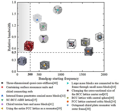
To demonstrate the advantages of the metamaterial proposed in this study more clearly, the starting frequencies and relative bandwidths of the bandgaps of three-dimensional single-phase metamaterials from other recent literature is plotted in for comparison. As can be seen from the figure, the metamaterial proposed in this study possess the advantages of low frequency (starting frequency below 300 Hz) and wide frequency domain (relative bandwidth above 0.5) over the other ones. At the same time, it can be also calculated that, under these structural parameters, the relative volume of a single cell of the metamaterial is only 20.2%, showing the advantage of lightweight.
Figure 10. Comparison of the bandgap starting frequency and relative bandwidths of the elastic metamaterials proposed in this study with those in other literature.
3.5. Experimental test of vibration transmission properties
The accuracy of the bandgap characteristics calculated via finite element analysis needs to be validated through vibration experiments. The printed physical model and experimental setup are shown in (a). The results of the transmission characteristic curve obtained from the experiment are compared with those from numerical studies, as shown in (b). There are two bandgaps obtained from vibration simulation (the red shaded area in the figure), while the bandgap obtained from vibration experiment is only one (the area inside the blue dashed line in the figure), but the frequency range of this bandgap basically includes the range of the two bandgaps in the simulation results. It is maybe because that the nylon material has a certain damping. In the continuous change of the vibration excitation frequency, the damping characteristics prevent a small section of the passband between the two bandgaps from being reflected [Citation44–46]. In addition, there is a certain difference in the transmission loss values of the vibration between the simulation and experimental results. There are many factors that cause these differences: (1) The boundary condition used in the simulation is a free boundary, but it is difficult to achieve this ideal boundary condition in the experimental set-up. (2) The manufactured samples have printing defects, and the frame has slight deformation, which could consequently affect the structural stiffness and deformation behaviour. (3) 3D printing will cause the physical sample to have anisotropic properties, but the sample used in the simulation is isotropic. (4) The circular truncated cone used to expand the adhesive area of the sample has a certain impact on the transmission of sample vibration, causing a certain offset in the transmission characteristic curve.
Figure 11. (a) 3D printed array model and vibration experiment setup (b) Comparison of transmission characteristic curves obtained from simulation and experiment.
3.6. Damping-induced bandgap merging effect
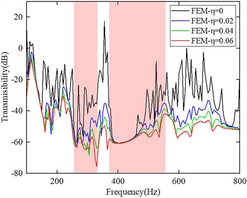
Damping is an inherent property of materials, and its impact is generally not negligible in practical engineering applications, especially for polymer materials, whose loss factor is often much greater than that of conventional metallic materials. To test the influence of damping magnitude on the bandgap range, different loss factors η (η takes 0, 0.02, 0.04, 0.06, respectively) were assigned to the material during the calculation of vibration transmission characteristics, with η = 0 indicating no damping. The transmission characteristics curves calculated under different loss factors are shown in . It can be clearly seen that when there is no damping, there exists a distinct passband between the two bandgaps in the transmission characteristics curve, and vibrations within this frequency range are not effectively suppressed. As the damping loss factor increases, such passband becomes less and less distinct. When the loss factor reaches 0.06, the passband almost disappears, and the two bandgaps merge into a larger bandgap. This simulation result is highly consistent with the experimental results. Moreover, due to the effect of damping, the relative bandwidth increases to 0.741, and the vibration isolation performance is enhanced. Additionally, the absence of a passband between the two bandgaps is more favourable for practical engineering applications.
Figure 12. Transmission characteristic curves of the structure under different loss factors.
3.7. Experimental test of quasi-static compression behaviours
The load-bearing capacity of vibration isolation structures is very significant for the research of elastic metamaterials. A few scholars have conducted research on the load-bearing capacity of designed elastic metamaterials [Citation38,Citation39,Citation47,Citation48]. Therefore, we evaluate the compression performance of the elastic metamaterial unit cell proposed in this study. From the structural form of the metamaterial, it can be seen that its compressive strength and elastic modulus are mainly affected by the thickness of the frame. Therefore, samples with different frame thicknesses are selected for compression experiments. The physical samples are shown in (a), and the frame thicknesses are 1.5, 2, 2.5, and 3 mm, respectively. A unit cell with a frame thickness of t = 2 mm is used as an example to demonstrate the compression deformation process of metamaterials. The unit cell sample and the compression experiment device are shown in (b), and the load-displacement curve of the entire compression process is shown in (c). At the beginning of compression, the metamaterial is in the elastic stage, and the load increases linearly. When the compression displacement continues to increase to 0.7 mm, there is the maximum load-bearing capacity of the metamaterial, and the metamaterial yields. After continuing to compress, the load gradually reduces due to structural yielding. When the compression displacement reaches 6 mm, the four longitudinal support rods of the frame break one after another, and the load drops sharply. After that, the connecting rods and resonator on the surface of the elastic metamaterial continuously contact and separate, causing the load to fluctuate. When the compression displacement reaches 18 mm, the structure becomes dense, and the load rises sharply. (d) shows the load-displacement curve of the metamaterial with different frame thicknesses in the early stage of the compression test without fracture. (e) shows the change trend of the compressive strength and equivalent elastic modulus of the metamaterial with the change of frame thickness.
Figure 13. (a) Physical metamaterial unit cells with different frame thicknesses, from left to right, the frame thicknesses are 1.5, 2, 2.5, and 3 mm respectively (b) Metamaterial unit cell sample with a frame thickness of 2 mm and the compression experiment setup (c) Full load-displacement curve of the compression test of the metamaterial unit cell with a frame thickness of 2 mm (d) Load-displacement curves of metamaterials with different frame thicknesses in the early stage of the compression test before fracture occurred (e) Relationship between the compressive strength and equivalent elastic modulus of the metamaterial and the frame thickness.
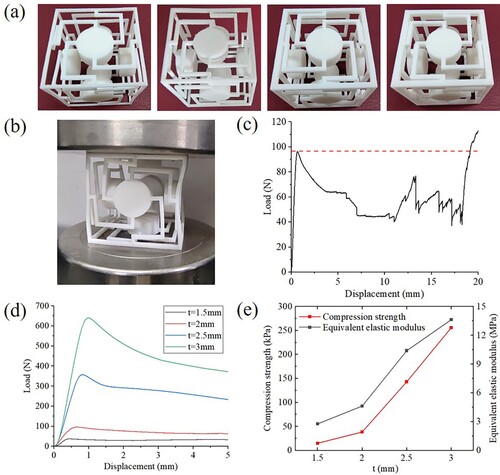
Based solely on the experimental results, the compressive strength of this structure is not particularly high. This is due to several factors, including defects in the sample manufacturing process and the fact that the experiment was conducted using a single cell, which introduces certain boundary effects. When compressed, the overall strength of the structure will reduce due to instability. However, in practical engineering applications, array structures are typically used, which can enhance the compressive strength. Despite these limitations, the elastic metamaterials designed in this study demonstrate good low-frequency vibration isolation capabilities while maintaining a certain level of compressive performance. This could potentially broaden the range of application scenarios to some extent.
4. Conclusions
This paper designs a three-dimensional elastic metamaterial with surface resonant units that can isolate low frequencies. The band characteristics of this metamaterial are analyzed through numerical simulation, and the influence of structural size and material properties on the bandgap frequency is analyzed parametrically. The transmission characteristic curve of the 3 × 3 × 3 array structure is calculated to test the vibration isolation effect of a finite number of cells. Subsequently, samples are manufactured by 3D printing for vibration experiment, further validating the reliability of the simulation results. Finally, a compression experiment is conducted to evaluate the compressive performance of the structure under different parameter designs. The main conclusions drawn from the research are as follows:
In this study, a three-dimensional elastic metamaterial with surface resonant units for low-frequency vibration isolation is designed and manufactured by 3D printing. The mechanism of bandgap generation is analyzed based on the characteristic modes of the bandgap edge of the metamaterial. The structure strengthens the locally resonance effect through the chiral structure on the surface, achieving low-frequency vibration isolation in the 253∼331 Hz and 370∼552 Hz frequency bands.
Multiple structural parameters of metamaterials are investigated in detail, and the effects of changes in structural parameters on the bandgap are analyzed to provide options for different engineering vibration isolation needs.
For the same structure of single-material elastic metamaterials, the bandgap frequency depends only on the transverse wave speed of its material, and the relative bandwidth is basically not affected by the material properties. Therefore, when facing the need for vibration isolation at different frequencies, not only can different structural parameters be selected, but also different materials can be used for manufacturing. Meanwhile, when choosing materials, other physical and chemical properties of the material, such as corrosion resistance and thermal expansion coefficient, should be considered to better adapt to the engineering environment.
At the end of this article, compression experiments are conducted. Different frame thicknesses can be selected according to the size of the load, providing theoretical guidance and data support for engineering applications that need to balance vibration isolation and load-bearing.
Data availability statement
Data will be made available on request.
Disclosure statement
No potential conflict of interest was reported by the author(s).
Additional information
Funding
References
- Li F, Zhang Q, Wang Z, et al. A new three-dimensional re-entrant negative Poisson’s ratio metamaterial with tunable stiffness. Eng Struct. 2024;306:117793. doi:10.1016/j.engstruct.2024.117793
- Pan Y, Zhou Y, Gao Q, et al. A novel 3D polygonal double-negative mechanical metamaterial with negative stiffness and negative Poisson’s ratio. Compos Struct. 2024;331:117878. doi:10.1016/j.compstruct.2024.117878
- Yao Y, He LH, Jin JH, et al. A novel design of mechanical metamaterial incorporating multiple negative indexes. Mater Res Express. 2023;10(5):055801. doi:10.1088/2053-1591/accf02
- Danawe H, Tol S. Experimental realization of negative refraction and subwavelength imaging for flexural waves in phononic crystal plates. J Sound Vib. 2022;518:116552. doi:10.1016/j.jsv.2021.116552
- Gao F, Benchabane S, Bermak A, et al. On-chip tightly confined guiding and splitting of surface acoustic waves using line defects in phononic crystals. Adv Funct Mater. 2023;33(14):2213625. doi:10.1002/adfm.202213625
- Li M, Hu Y, Cheng J, et al. Elastic metasurfaces with tailored initial phase for broadband subwavelength focusing. Int J Mech Sci. 2024;268:109048. doi:10.1016/j.ijmecsci.2024.109048
- Martínez-Sala R, Sancho J, Sánchez JV, et al. Sound attenuation by sculpture. Nature. 1995;378(6554):241–241. doi:10.1038/378241a0
- Sigalas MM, Economou EN. Elastic and acoustic wave band structure. J Sound Vib. 1992;158(2):377–382. doi:10.1016/0022-460X(92)90059-7
- Liang HY, Yi XY, Shang QW, et al. The study of two- dimensional composite materials with wide band gap. Acta Phys Sin. 2007(5):2784–2789. doi:10.7498/aps.56.2784
- Alonso-Redondo E, Schmitt M, Urbach Z, et al. A new class of tunable hypersonic phononic crystals based on polymer-tethered colloids. Nat Commun. 2015;6(1):8309. doi:10.1038/ncomms9309
- Yu D, Hu G, Ding W, et al. Zero-thermal-expansion metamaterial with broadband vibration suppression. Int J Mech Sci. 2023;258:108590. doi:10.1016/j.ijmecsci.2023.108590
- Hsieh P-F, Wu T-T, Sun J-H. Three-dimensional phononic band gap calculations using the FDTD method and a PC cluster system. IEEE Trans Ultrason Ferroelectr Freq Control. 2006;53(1):148–158. doi:10.1109/TUFFC.2006.1588400
- Zhang X, Liu Z, Liu Y, et al. Elastic wave band gaps for three-dimensional phononic crystals with two structural units. Phys Lett A. 2003;313(5–6):455–460. doi:10.1016/S0375-9601(03)00807-7
- Wang YZ, Li FM, Kishimoto K, et al. Wave band gaps in three-dimensional periodic piezoelectric structures. Mech Res Commun. 2009;36(4):461–468. doi:10.1016/j.mechrescom.2009.01.003
- Pennec Y, Vasseur JO, Djafari-Rouhani B, et al. Two-dimensional phononic crystals: Examples and applications. Surf Sci Rep. 2010;65(8):229–291. doi:10.1016/j.surfrep.2010.08.002
- Liu Z, Chan CT, Sheng P. Analytic model of phononic crystals with local resonances. Phys Rev B. 2005;71(1):014103. doi:10.1103/PhysRevB.71.014103
- Goffaux C, Sánchez-Dehesa J, Yeyati AL, et al. Evidence of fano-like interference phenomena in locally resonant materials. Phys Rev Lett. 2002;88(22):225502. doi:10.1103/PhysRevLett.88.225502
- Xiao W, Zeng GW, Cheng YS. Flexural vibration band gaps in a thin plate containing a periodic array of hemmed discs. Appl Acoust. 2008;69(3):255–261. doi:10.1016/j.apacoust.2006.09.003
- Oudich M, Li Y, Assouar BM, et al. A sonic band gap based on the locally resonant phononic plates with stubs. New J Phys. 2010;12(8):083049. doi:10.1088/1367-2630/12/8/083049
- Liu Z, Zhang X, Mao Y, et al. Locally resonant sonic materials. Science. 2000;289(5485):1734–1736. doi:10.1126/science.289.5485.1734
- Krushynska AO, Kouznetsova VG, Geers MGD. Towards optimal design of locally resonant acoustic metamaterials. J Mech Phys Solids. 2014;71:179–196. doi:10.1016/j.jmps.2014.07.004
- Yin J, Peng HJ, Zhang S, et al. Design of nacreous composite material for vibration isolation based on band gap manipulation. Comput Mater Sci. 2015;102:126–134. doi:10.1016/j.commatsci.2015.01.032
- Guo J, Li Y, Xiao Y, et al. Multiscale modeling and design of lattice truss core sandwich metastructures for broadband low-frequency vibration reduction. Compos Struct. 2022;289:115463. doi:10.1016/j.compstruct.2022.115463
- Wu JH, Zhang SW, Shen L. Low-frequency vibration characteristics of periodic spiral resonators in phononic crystal plates. J Mech Eng. 2013;49(10):62–69. doi:10.3901/JME.2013.10.062
- Badreddine Assouar M, Sun JH, Lin FS, et al. Hybrid phononic crystal plates for lowering and widening acoustic band gaps. Ultrasonics. 2014;54(8):2159–2164. doi:10.1016/j.ultras.2014.06.008
- Matlack KH, Bauhofer A, Krödel S, et al. Composite 3D-printed metastructures for low-frequency and broadband vibration absorption. Proc Natl Acad Sci USA. 2016;113(30):8386–8390. doi:10.1073/pnas.1600171113
- Baravelli E, Ruzzene M. Internally resonating lattices for bandgap generation and low-frequency vibration control. J Sound Vib. 2013;332(25):6562–6579. doi:10.1016/j.jsv.2013.08.014
- Cheng Q, Guo H, Yuan T, et al. Topological design of square lattice structure for broad and multiple band gaps in low-frequency range. Extreme Mech Lett. 2020;35:100632. doi:10.1016/j.eml.2020.100632
- Mizukami K, Kawaguchi T, Ogi K, et al. Three-dimensional printing of locally resonant carbon-fiber composite metastructures for attenuation of broadband vibration. Compos Struct. 2021;255:112949. doi:10.1016/j.compstruct.2020.112949
- Hou X, Feng J, An X, et al. Hybrid rod-plate lattice metamaterial with broadband vibration attenuation. Appl Acoust. 2024;216:109822. doi:10.1016/j.apacoust.2023.109822
- Muhammad, Lim CW, Li JTH, et al. Lightweight architected lattice phononic crystals with broadband and multiband vibration mitigation characteristics. Extreme Mech Lett. 2020;41:100994. doi:10.1016/j.eml.2020.100994
- Jiang W, Yin M, Liao Q, et al. Three-dimensional single-phase elastic metamaterial for low-frequency and broadband vibration mitigation. Int J Mech Sci. 2021;190:106023. doi:10.1016/j.ijmecsci.2020.106023
- D’Alessandro L, Ardito R, Braghin F, et al. Low frequency 3D ultra-wide vibration attenuation via elastic metamaterial. Sci Rep. 2019;9(1):8039. doi:10.1038/s41598-019-44507-6
- Elmadih W, Chronopoulos D, Syam WP, et al. Three-dimensional resonating metamaterials for low-frequency vibration attenuation. Sci Rep. 2019;9(1):11503. doi:10.1038/s41598-019-47644-0
- Sheng H, He MX, Zhao J, et al. The ABH-based lattice structure for load bearing and vibration suppression. Int J Mech Sci. 2023;252:108378. doi:10.1016/j.ijmecsci.2023.108378
- Ruan H, Li D. Band gap characteristics of bionic acoustic metamaterials based on spider web. Eng Struct. 2024;308:118003. doi:10.1016/j.engstruct.2024.118003
- Yong J, Dong Y, Bao Y, et al. High load-bearing and low-frequency multi-broadband design of innovative composite meta-material. Mater Des. 2024;241:112945. doi:10.1016/j.matdes.2024.112945
- An X, Lai C, He W, et al. Three-dimensional chiral meta-plate lattice structures for broad band vibration suppression and sound absorption. Composites, Part B. 2021;224:109232. doi:10.1016/j.compositesb.2021.109232
- Jiang W, Yin G, Xie L, et al. Multifunctional 3D lattice metamaterials for vibration mitigation and energy absorption. Int J Mech Sci. 2022;233:107678. doi:10.1016/j.ijmecsci.2022.107678
- Lin Q, Zhou J, Wang K, et al. Three-dimensional quasi-zero-stiffness metamaterial for low-frequency and wide complete band gap. Compos Struct. 2023;307:116656. doi:10.1016/j.compstruct.2022.116656
- Ding W, Chen T, Chen C, et al. A three-dimensional twisted phononic crystal with omnidirectional bandgap based on inertial amplification by utilizing translation-rotation coupling. J Sound Vib. 2022;541:117307. doi:10.1016/j.jsv.2022.117307
- Li L, Yang F, Guo Z, et al. Truss-plate hybrid lattice metamaterials with broadband vibration attenuation and enhanced energy absorption. Virtual Phys Prototyp. 2024;19(1):e2345386. doi:10.1080/17452759.2024.2345386
- D’Alessandro L, Belloni E, Ardito R, et al. Modeling and experimental verification of an ultra-wide bandgap in 3D phononic crystal. Appl Phys Lett. 2016;109(22):221907. doi:10.1063/1.4971290
- Muhammad, Lim CW. Phononic metastructures with ultrawide low frequency three-dimensional bandgaps as broadband low frequency filter. Sci Rep. 2021;11. doi:10.1038/s41598-021-86520-8
- D’Alessandro L, Zega V, Ardito R, et al. 3D auxetic single material periodic structure with ultra-wide tunable bandgap. Sci Rep. 2018;8(1):2262. doi:10.1038/s41598-018-19963-1
- Ding W. Isotacticity in chiral phononic crystals for low-frequency bandgap. Int J Mech Sci. 2024. doi:10.1016/j.ijmecsci.2023.108678
- An X, Lai C, He W, et al. Three-dimensional meta-truss lattice composite structures with vibration isolation performance. Extreme Mech Lett. 2019;33:100577. doi:10.1016/j.eml.2019.100577
- Zhang L, Bai Z, Zhang Q, et al. On vibration isolation performance and crashworthiness of a three-dimensional lattice metamaterial. Eng Struct. 2023;292:116510. doi:10.1016/j.engstruct.2023.116510